

Page 1

CD Series
Cabinet Dryer
Date: Feb, 2019
Version: Ver.B (English)
Page 2

Page 3

Contents
1. General Description ..................................................................................... 5
1.1 Coding Principle ...................................................................................... 6
1.2 Feature .................................................................................................... 6
1.3 Technical Specifications .......................................................................... 8
1.3.1 Outline Drawing ............................................................................. 8
1.3.2 Specifications ................................................................................ 8
1.4 Safety Regulations .................................................................................. 9
1.4.1 Safety Signs and Labels ................................................................ 9
1.4.2 Transportation and Storage of the Machine................................... 9
1.5 Exemption Clause ................................................................................. 11
2. Structure Characteristics and Working Principle .................................... 12
2.1 Main Functions ...................................................................................... 12
2.2 Working Principle Illustration ................................................................. 12
3. Installation and Debugging ........................................................................ 13
3.1 Attentions During Installation ................................................................ 13
3.2 Machine Ins Tallation Distance ............................................................. 13
3.3 Check the Rotation Direction of Blower ................................................. 14
4. Application and Operation ......................................................................... 15
4.1 Test ....................................................................................................... 15
4.2 Setting Temperature ............................................................................. 15
4.2.1 Keys Operature Instruction .......................................................... 16
4.3 Adjustment of Air Rate .......................................................................... 17
4.4 Start-up Timer Setting ........................................................................... 17
4.5 Setting the Over-thermal Protector ........................................................ 18
5. Trouble-shooting ........................................................................................ 19
6. Maintenance and Repair ............................................................................ 20
6.1 Maintenance Schedule .......................................................................... 21
6.1.1 About the Machine ....................................................................... 21
6.1.2 Electrical Installation .................................................................... 21
3(21)
Page 4

6.1.3 Daily Checking ............................................................................. 21
6.1.4 Weekly Checking ......................................................................... 21
6.1.5 Monthly Checking ........................................................................ 21
Table Index
Table 1-1: Specifications .................................................................................... 8
Picture Index
Picture 1-1: Outline Drawing ............................................................................... 8
Picture 2-1: Working Principle Illustration ......................................................... 12
Picture 3-1: Machine Ins Tallation Distance ...................................................... 13
Picture 3-2: Blower Inlet / Outlet ....................................................................... 14
Picture 4-1: Temp. Controller ............................................................................ 15
Picture 4-2: Adjustment of Air Rate................................................................... 17
Picture 4-3: Start-up Timer Setting ................................................................... 18
Picture 4-4: Setting the Over-thermal Protector ................................................ 18
4(21)
Page 5
1. General Description
Read this manual carefully before operation to prevent damage of the
machine or personal injuries.
Forbidden to process flammable or toxic material!
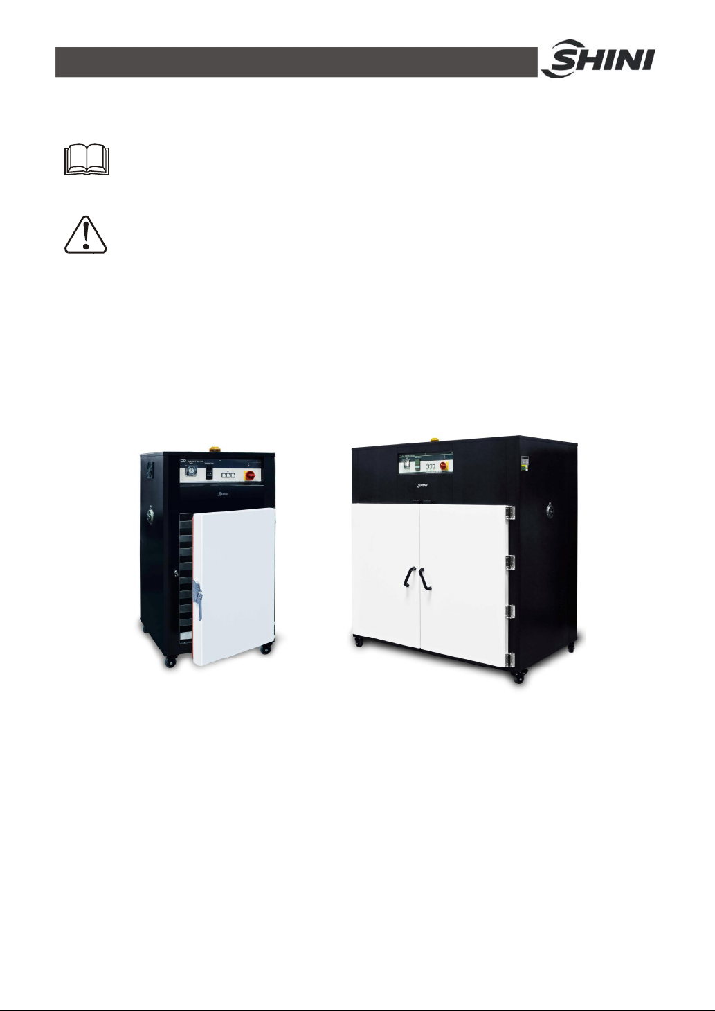
CD series of cabinet dryer are mostly used for simultaneous drying of different
kinds of polymers in small quantities or for drying materials for trial moulding. They
can also be applied in electronic engineering, electroplating, pharmacy, paint
baking, printing industries, etc. for preheating or drying related products.
Model: CD-9 Model: CD-20-HT
5(21)
Page 6
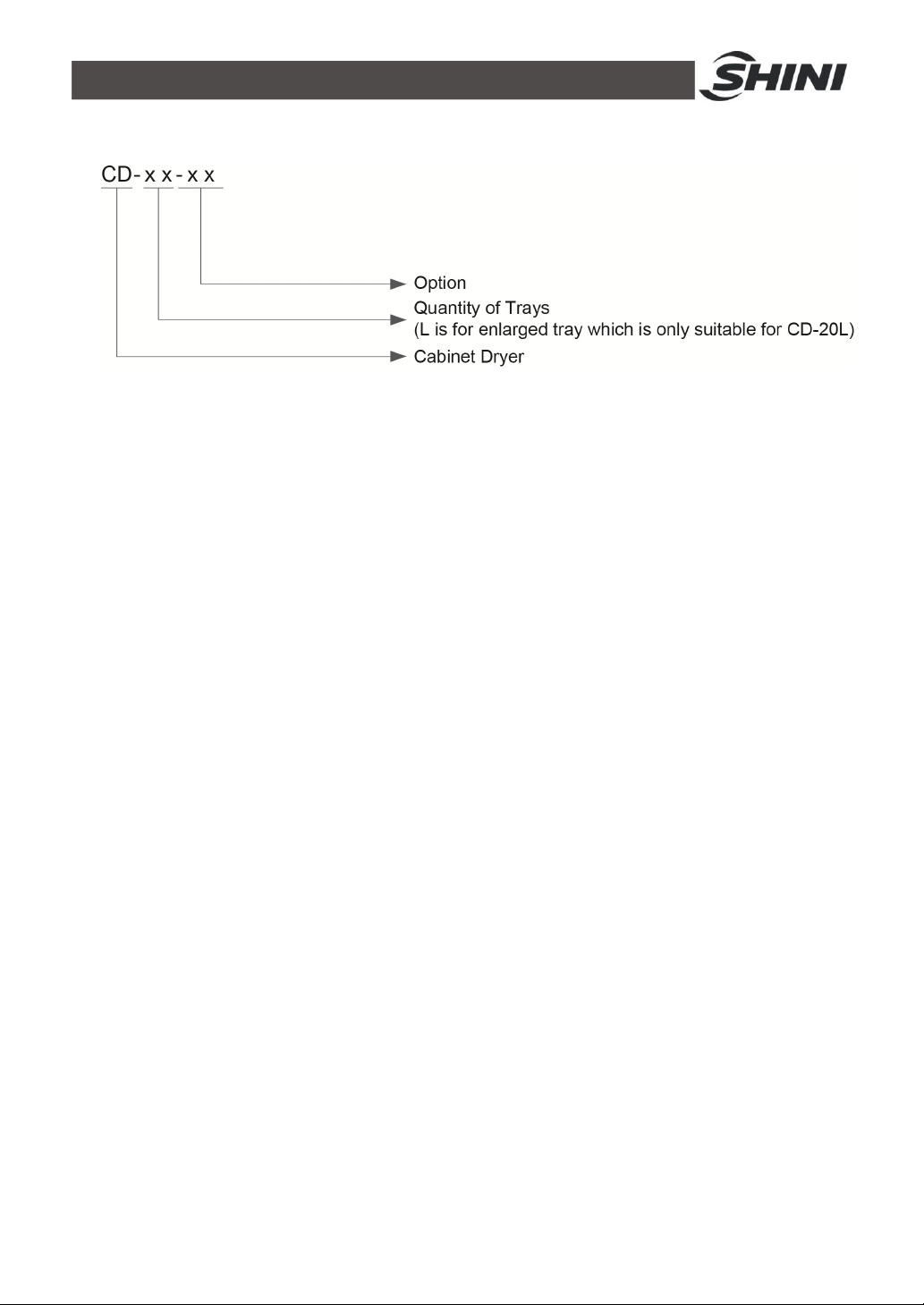
1.1 Coding Principle
1.2 Feature
l Accurate P.I.D. temperature control to achieve an even drying effect.
l Air-proofed insulative door can maintain temperature constantly inside to
reduce energy consumption.
l Stainless steel tray and liner bring no contamination to materials.
l Unique design of adjustable air inlet and exhaust.
l 24 hours timer, easy to operate.
l Overheat protector can prevent excessive drying.
l Motor overload relay.
l Visible alarm to indicate troubles immediately
l Power would be automatically cut off when drying temperature exceeds
set deviation value to protect thermal fuse.
All service work should be carried out by a person with technical training or
corresponding professional experience. The manual contains instructions for both
handling and servicing. Chapter 6, which contains service instructions intended for
service engineers. Other chapters contain instructions for the daily operator.
Any modifications of the machine must be approved by SHINI in order to avoid
personal injury and damage to machine. We shall not be liable for any damage
caused by unauthorized change of the machine.
Our company provides excellent after-sales service. Should you have any
problem during using the machine, please contact the company or the local
vendor.
6(21)
Page 7

Headquarter and Taipei factory:
Tel: (886) 2 2680 9119
Shini Plastics Technologies (Dongguan), Inc:
Tel: (86) 769 8111 6600
Shini Plastics Technologies India Pvt.Ltd.:
Tel: (91) 250 3021 166
7(21)
Page 8
1.3 Technical Specifications
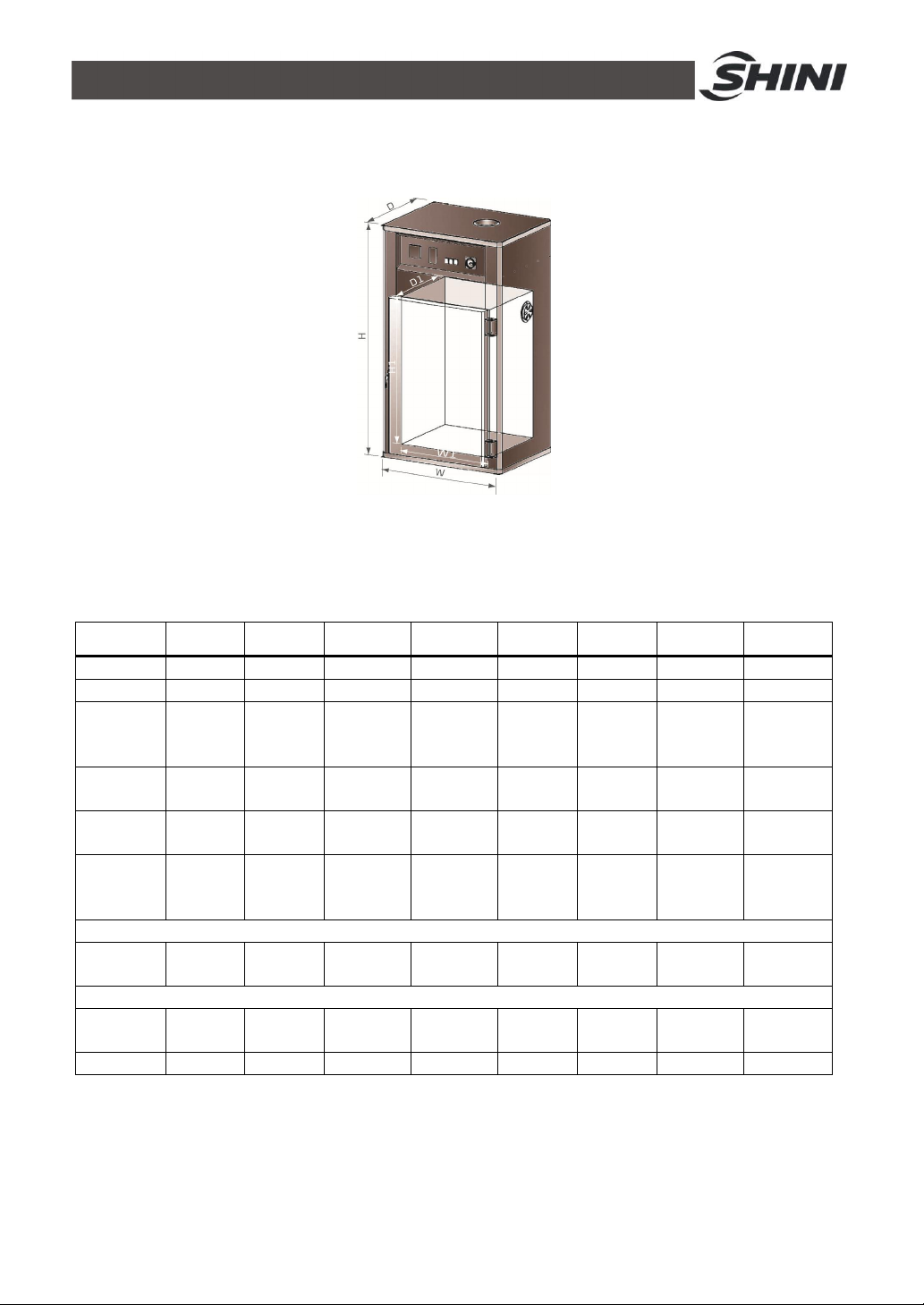
1.3.1 Outline Drawing
Picture 1-1: Outline Drawing
1.3.2 Specifications
Table 1-1: Specifications
Model CD-5 CD-9 CD-20 CD-20L CD-5-HT CD-9-HT CD-20-HT CD-20L-HT
Ver. B B B B B B B B
Heater(kW)
Blower
(kW, 50/60
Hz)
Highest
Temp.()℃
Tray
Quantity
Total
Capacity
(kg)
Outer Dimensions H×W×D (mm)
- 1200×800
Inner Dimensions H1×W1×D1 (mm)
- 660×600
Weight(kg)
Notes: 1) "HT" stands for heat insulation model, the surface temperature We reserve the right to change
of which will not be more than 80℃ when setup temperature is 250℃. specifications without prior notice.
2) When drying temperature is below 150℃, "HT" models can keep internal temperature accuracy
of ±5℃, when it is above 150℃, internal temperature accuracy is ±12℃.
3) Above loading capacity is based on pellet material of 0.65kg/L(5.4Ib/gal) in bulk density and 3~5mm(0.12~0.2inch) in
diameter.
4) Power: 3Φ,230/400/460/575VAC, 50/60Hz.
4 4.5 9 18 4 4.5 9 8
0.37/0.55 0.37/0.55
200 200 200 200 250 250 250 250
5 9 20 20 5 9 20 20
50 90 200 450 50 90 200 450
1440×800
×610
×550
150 180 415 550 200 252 587 778
×610
900×600
×550
1.5 1.5 0.37/0.55
1700×1210
×760
1000×990
×800
1865×1800
×1060
1200×1600
×1000
1380×860
×731
660×600
×550
0.55 1.5 1.5
1640×920
×731
900×600
×550
1887×1310
×1032
1000×990
×800
2052×1900
1200×1600
8(21)
×1232
×1000
Page 9
1.4 Safety Regulations
1.4.1 Safety Signs and Labels
Please abide by the safety guide when you operate the machine so as to prevent
damage of the machine and personal injuries.
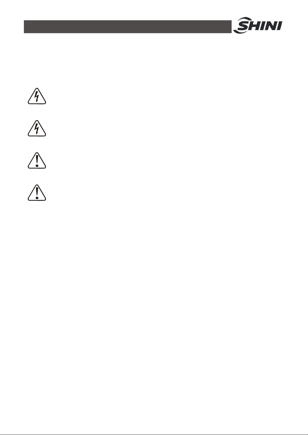
All electrical components should be installed by qualified electricians.
Turn off main switch and control switch during repair and maintenance.
Warning! High voltage!
This mark is attached on the cover of the control box.
Warning! Be careful!
Be more careful when this mark appears.
Attention!
No need for regular inspection because all the electrical parts in the control
unit are fixed tightly!
1.4.2 Transportation and Storage of the Machine
Transportation and storage of the machine
1) CD series are packed in crates or plywood cases with wooden pallet at the
bottom, suitable for quick positioning by fork lift.
2) After unpacked, castors equipped on the machine can be used for ease of
movement.
3) Do not rotate the machine and avoid collision with other objects during
transportation to prevent improper functioning.
4) The structure of the machine is well-balanced, although it should also be
handled with care when lifting the machine for fear of falling down.
5) The machine and its attached parts can be kept at a temperature from
-25℃ to +55℃ for long distance transportation and for a short distance, it
can be transported with temperature under +70℃.
Storage
1) CD series should be stored indoors with temperature kept from 5℃to 40℃
9(21)
Page 10

and humidity below 80%.
2) Disconnect all power supply and turn off main switch and control switch.
3) Keep the whole machine, especially the electrical components away from
water to avoid potential troubles caused by the water.
4) Plastic film should be used to protect the machine from dust and rains.
Working environment
1) Indoors in a dry environment with max. temperature +45℃ and humidity
no more than 80%.
Do not use the machine:
1) If it is with a damaged cord.
2) On a wet floor or when it is exposed to rain to avoid electrical shock.
3) If it has been dropped or damaged until it is checked or fixed by a qualified
serviceman.
4) This equipment works normally in the environment with altitude within
3000m.
5) At least a clearance of 1m surrounding the equipment is required during
operation. Keep this equipment away from flammable sources at least two
meters.
6) Avoid vibration, magnetic disturbance at the operation area.
Rejected parts disposal
When the equipment has run out its life time and can not be used any more,
unplug the power supply and dispose of it properly according to local code.
Fire hazard
In case of fire, Co2 dry powder fire extinguisher should be applied.
10(21)
Page 11

1.5 Exemption Clause
The following statements clarify the responsibilities and regulations born by any
buyer or user who purchases products and accessories from Shini (including
employees and agents).
Shini is exempted from liability for any costs, fees, claims and losses caused by
reasons below:
1) Any careless or man-made installations, operation and maintenances
upon machines without referring to the Manual prior to machine using.
2) Any incidents beyond human reasonable controls, which include
man-made vicious or deliberate damages or abnormal power, and
machine faults caused by irresistible natural disasters including fire, flood,
storm and earthquake.
3) Any operational actions that are not authorized by Shini upon machine,
including adding or replacing accessories, dismantling, delivering or
repairing.
4) Employing consumables or oil media that are not appointed by Shini.
11(21)
Page 12
2. Structure Characteristics and Working Principle
2.1 Main Functions
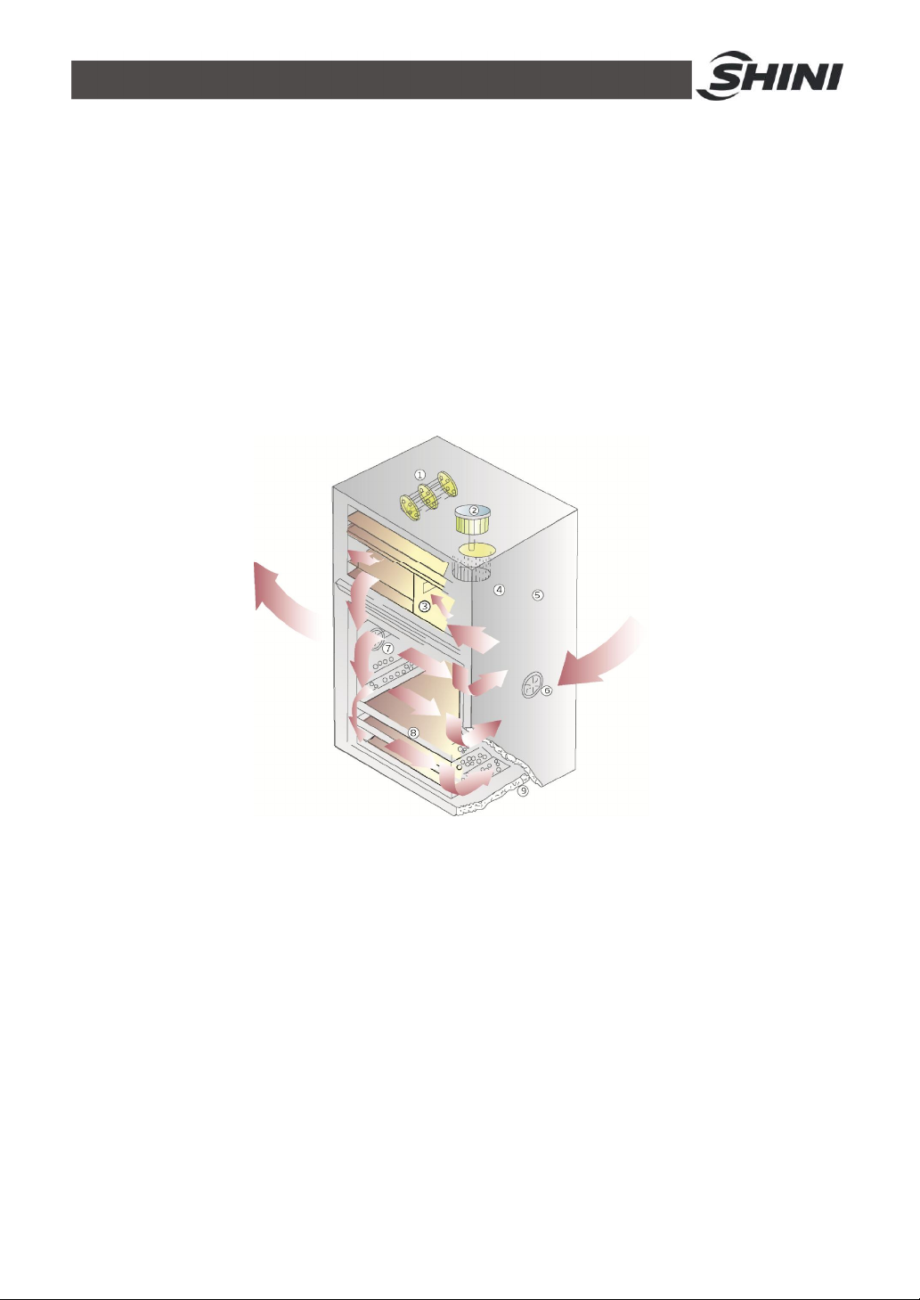
For cabinet dryer, materials to be dried are placed on the stainless steel made
moveable material trays. During operation, process air will flow to heating wire
and be heated up to required temperature, then flow through a manifold with
evenly scattered holes. Moisture air is sent out through air exhaust port. It is
designed to achieve an even drying effect.
2.2 Working Principle Illustration
Names of Parts:
1. Heating Coil 2. Air Inlet Blower 3. Air Chamber
4. Multi-vane Impeller 5. Paint-baked Cover 6. Air Inlet
7. Air Exhaust 8. Stainless Steel Tray 9. Heat-resistant Layer
Picture 2-1: Working Principle Illustration
12(21)
Page 13
3. Installation and Debugging
Install the CD Cabinet Dryer at a proper place where is easy for service and
maintenance.
3.1 Attentions During Installation
1) Make sure voltage and frequency of the power source comply with those
indicated on the manufacture's plate, which is attached to the machine.
2) Power cable and earth connections should conform with local regulations.
3) Use independent power cable and ON/OFF switch. The cable's size
should not smaller than those applied in the control box.
4) The power cable connection terminals should be tightened securely.
5) The machine requires a 3-phase 4-wire power source, connect the power
lead (L1, L2, L3) to the live wires, and the earth (PE) to the ground.
6) Power supply requirements:
Main power voltage: ±5%
Main power frequency: ±2%
7) Please refer to electrical drawing of each model to get the detailed power
supply specifications
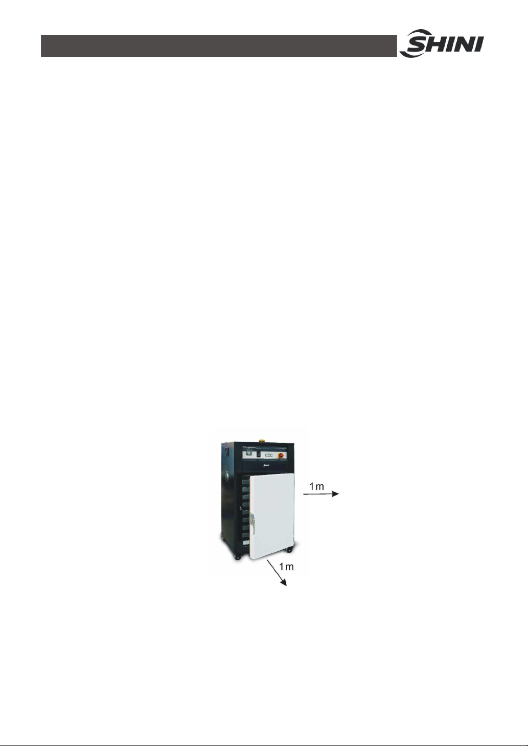
3.2 Machine Ins Tallation Distance
Picture 3-1: Machine Ins Tallation Distance
Note: Keep the machine 2M from the combustible distance.
13(21)
Page 14
3.3 Check the Rotation Direction of Blower
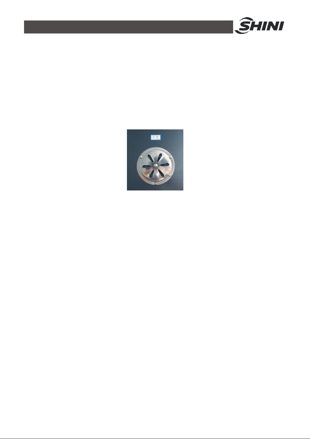
1) Check whether the wind direction of inlet and outlet on the two sides of oven is
right.
2) If the rotation direction is not right:
a. Stop the machine.
b. Turn off the main switch.
c. Change any two lines of the main power supply 's three lines.
d. Stop the machine, and check it again.
Picture 3-2: Blower Inlet / Outlet
14(21)
Page 15
4. Application and Operation
Open the distribution box and connect the power source in accordance with wiring
diagram. Make sure that the power voltage is in compliance with the required
specifications.
Notes: Before connecting, the main switch and heat switch
should be off.
4.1 Test
After all wires are connected, turn the main switch and the heater switch to “ON”,
then the pilot lamp light, observe if the rotating direction of blower is consistent
with the arrow. If not, exchange any two power cables.
4.2 Setting Temperature
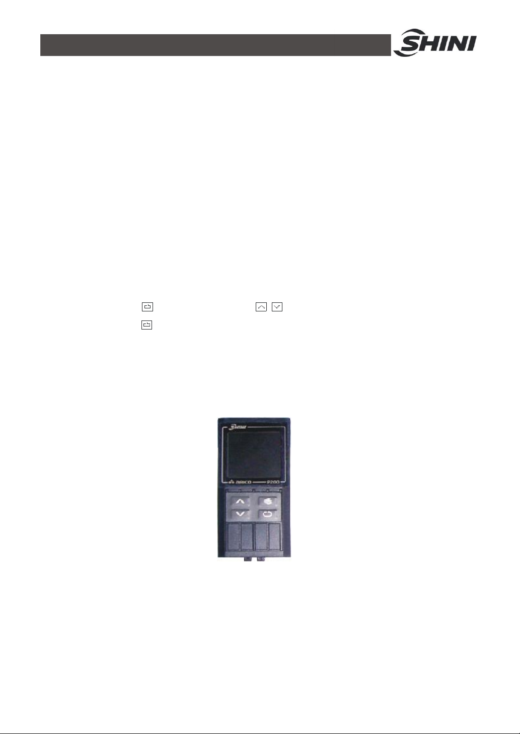
Firstly press key , then press keys to adjust temperature , finally press
confirmative key to confirm the adjusting. Use temperature adjustor together
with material dry thermometer to set the temperature. After heating for a period of
time, the yellow light and red light will flash alternatively, which indicates that the
setting temperature value has been reached, at that time the actual temperature
of temperature controller and setting temperature are the same.
Picture 4-1: Temp. Controller
15(21)
Page 16

4.2.1 Keys Operature Instruction
Parameter layer selection key
1) If select this key under common condition, system will enter Parameter
layer selection mode, and press this key again to Select parameter
layer. If want to enter parameter mode, please Press key.
2) If press this key under parameter mode, system will out of the
parameter mode and enter the parameter layer selection mode.
3) Under setting mode, press the selection key to store the parameters
and out of the setting mode, enter the parameter mode.
4) Under all modes, press this key for 2 seconds to skip back to
common condition.
Setting keys
1) Under common mode, press setting key to set the 'setting value'
2) Under parameter layer selection mode, press setting key to skip back
3) Under parameter mode, press this key, system will enter setting mode,
4) Under setting mode, press setting key to select the setting numbers or
Up key
1) Under parameter layer selection mode, press up key to enter
2) Under parameter mode, press up key to select the parameters of this
3) Under setting mode, press up key to increase the parameters' value
Down key
directly.
the last parameter layer.
and may set the parameters.
store the parameters and skip back the parameter mode.
parameter mode.
parameter layer.
until their upper limit.
1) Under parameter layer selection mode, press down key to enter
parameter mode.
16(21)
Page 17
2) Under parameter mode, press down key to select the parameters of
this parameter layer.
3) Under setting mode, press down key to increase the parameters' value
until their lower limit.
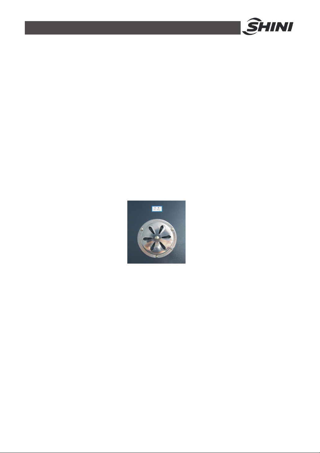
4.3 Adjustment of Air Rate
Adjustment of air rate is the most important factor for the drying result, should
adjust the air outlet and inlet when drying different material.
For example:
1) When heat and brake the electronic, galvanized and baked-finish products,
the air-inlet and air-outlet should be closed completely.
2) When dry up the plastic materials and other products contained much
moisture, the air-inlet and air-outlet should be opened properly.
Picture 4-2: Adjustment of Air Rate
4.4 Start-up Timer Setting
Turn on timer switch after all switch has been on, take down the glassy shield
outside of the timer, then push the small black switch to "Auto". Set current time
and drying time required, cover the glassy shield. Therefore the cabinet dryer will
run automatically till drying time.
17(21)
Page 18
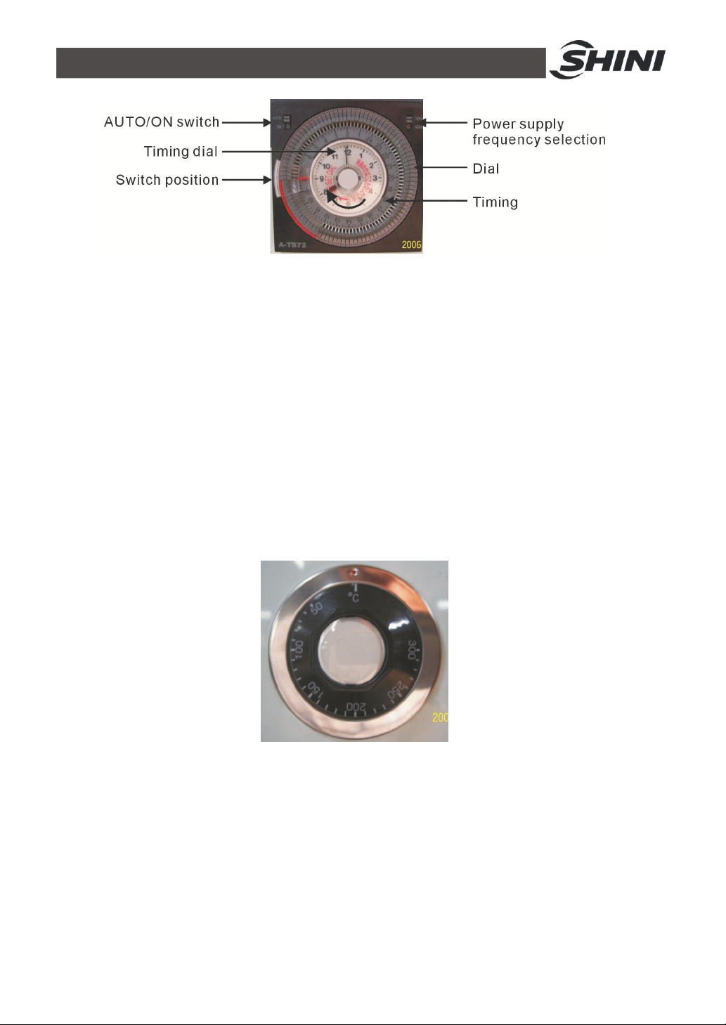
Picture 4-3: Start-up Timer Setting
Output setting
Open setting: Reverse the setting section of dial entad, at this time, red mark
appears in the dial.(shown in the above picture)
Close setting: Reverse the setting section of dial to the outside, the red mark
disappears, then rotate the timing dial to the switch position.
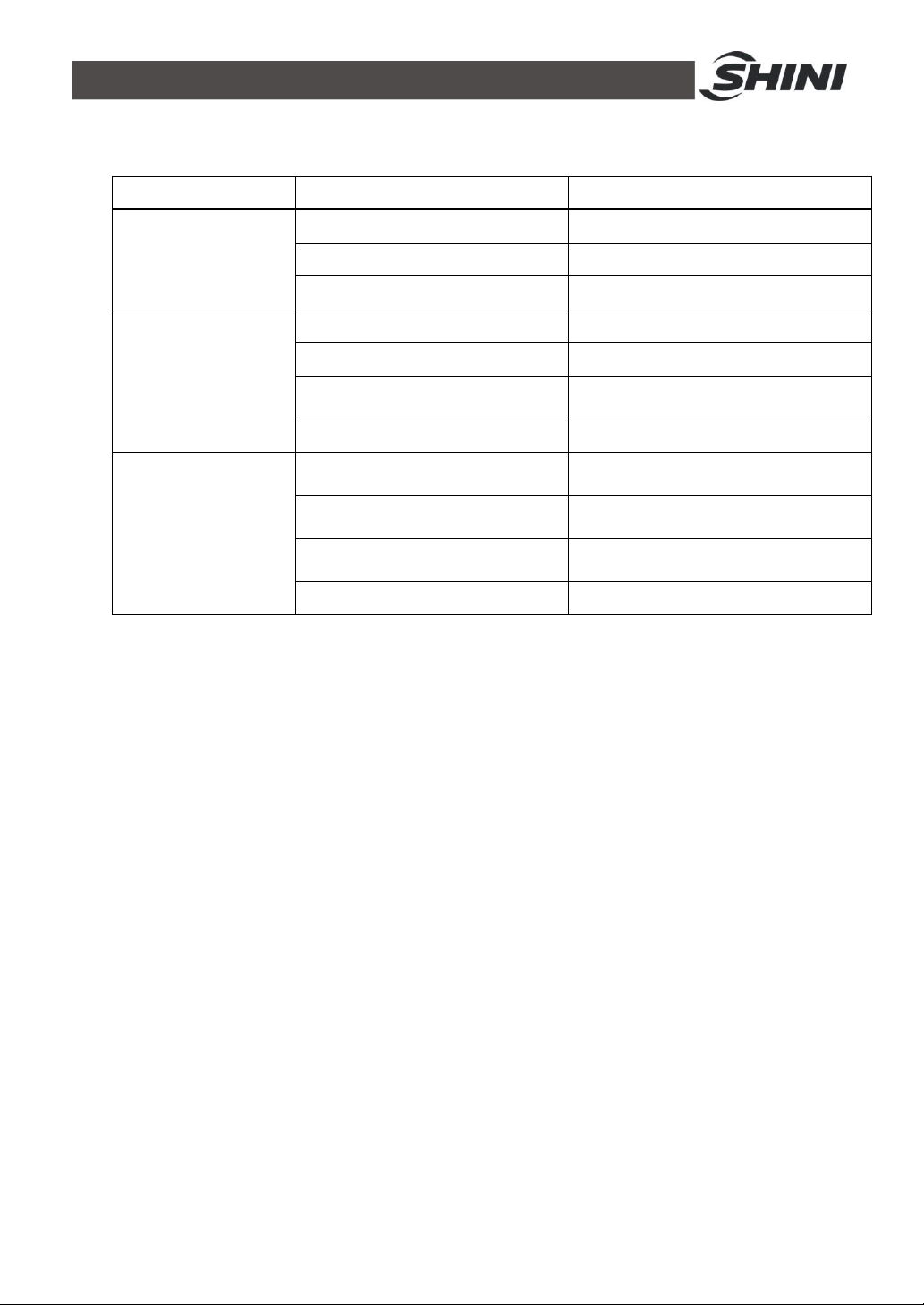
4.5 Setting the Over-thermal Protector
Over-thermal protector will be used when the actual heating temperature exceeds
the setting temperature to protect the motor and heater. And it's setting
temperature should be higher than that of thermometer.
Picture 4-4: Setting the Over-thermal Protector
18(21)
Page 19
5. Trouble-shooting
Fault Possible reasons Solution
It doesn't start after
turning on the main
switch.
The motor doesn't
run.
The temperature is
abnormal.
1. The motor switch isn't open.
2. The fuse is broken.
3. The transformer is burnt out.
1. The motor switch isn't open.
2. The circuit breaker trips.
3. The magnet contactor
breakdowns.
4. The motor is burned out.
1. The temperature controller
breakdowns.
2. The temperature contactor
breakdowns.
3. The magnet contactor
breakdowns.
4. The heater breakdowns.
1. Turn on the motor switch.
2. Replace a new fuse.
3. Replace a new transformer.
1. Turn on the motor switch.
2. Press "RESET" key.
3. Replace a new magnet contactor.
4. Replace a new motor.
1. Replace it.
2. Replace it.
3. Replace it.
4. Replace it.
19(21)
Page 20
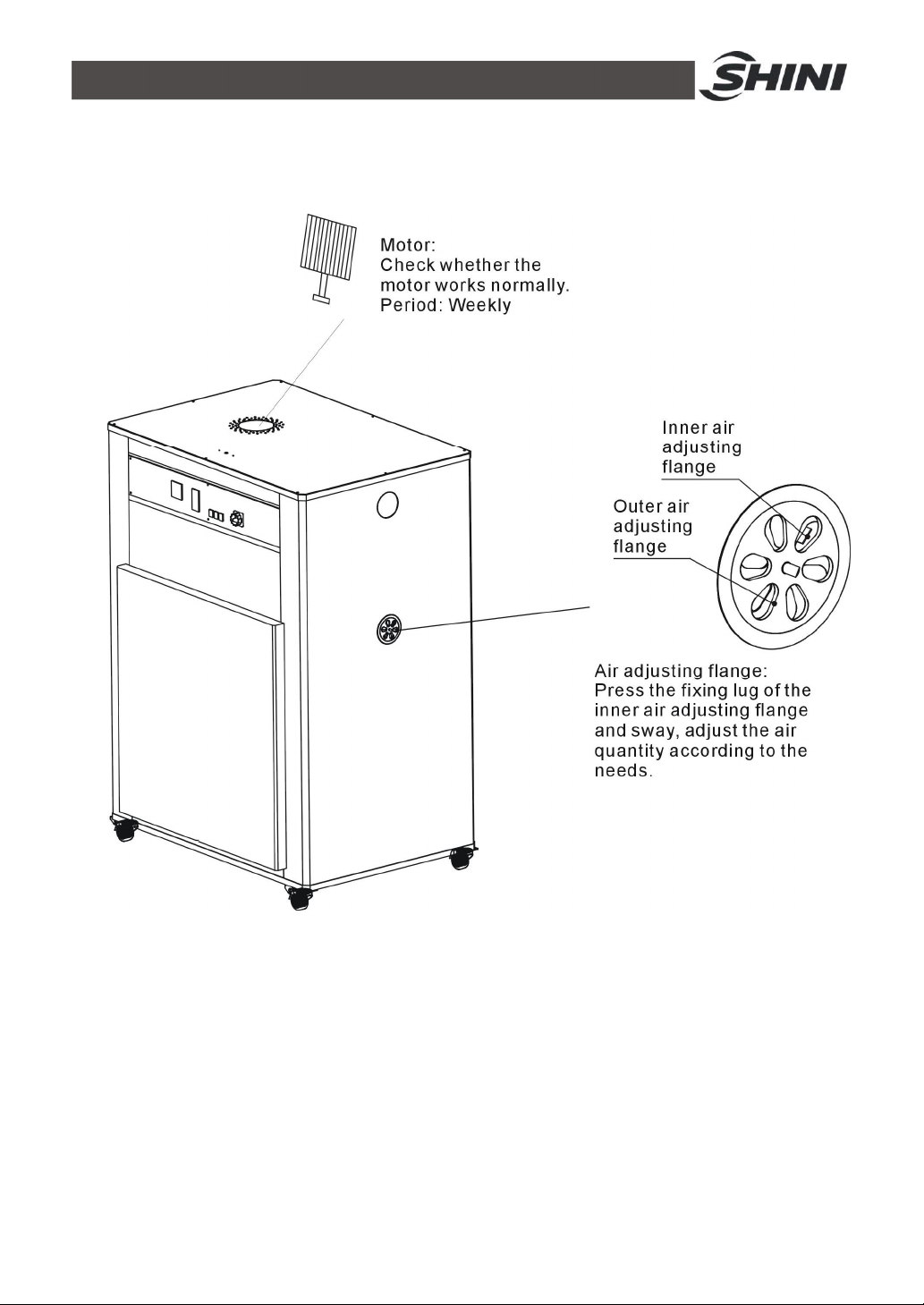
6. Maintenance and Repair
Clear off the dust on the motor fan periodically, avoid the damage to the blower.
20(21)
Page 21
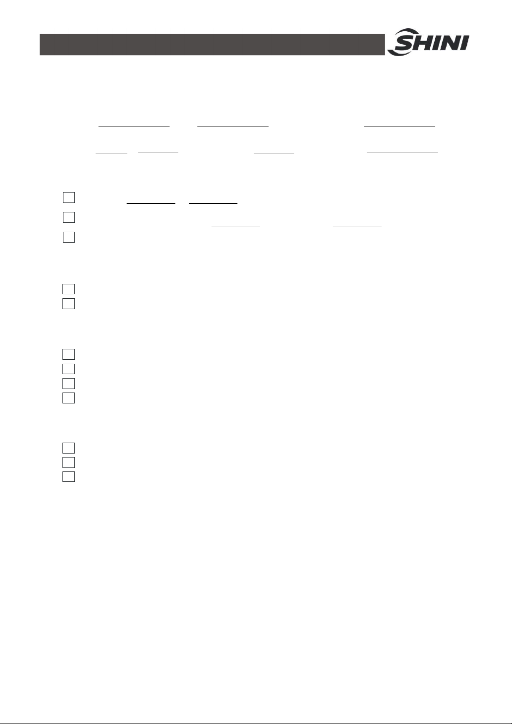
6.1 Maintenance Schedule
6.1.1 About the Machine
Model SN Manufacture date
Voltage Ф V Frequency Hz Power kW
6.1.2 Electrical Installation
Voltage: V Hz
Fuse melt current: 1 Phase A 3 Phase A
Check phase sequence of the power supply.
6.1.3 Daily Checking
Check power supply wires.
Check the start/stop function.
6.1.4 Weekly Checking
Check the switches of the machine.
Check all the electrical wires.
Check the pipe heater.
Check motor overload relay.
6.1.5 Monthly Checking
Check the switches and automatism on-off of the machine.
Check the pipe heater.
Check if there are loose electrions.
21(21)
 Loading...