

Page 1

CAA-100 Series
Cable and Antenna
Analyzer
User’s Manual
Page 2

Shineway Technologies, Inc. - i-
Notices
Copyright© 2018, ShinewayTech, All rights reserved.
No part of this manual may be reproduced in any form or by any means (including
electronic storage and retrieval or translation into a foreign language) without prior
agreement and written consent from ShinewayTech as governed by international
copyright laws.
Warranty
The material contained in this document is subject to change without notice.
ShinewayTech makes no warranty of any kind with regard to this material,
including, but not limited to, the implied warranties of merchantability and fitness for a
particular purpose. ShinewayTech shall not be liable for errors contained herein or for
incidental or consequential damages in connection with furnishing, performance, or
use of this material.
The battery is a consumable part and is not subject to the CAA-100 Series cable and
antenna analyzer warranty.
ISO9001 Certification
Produced to ISO9001 International Quality System Standard as part of
ShinewayTech, objective of continually increasing customer satisfaction through
improved process control.
Page 3

CAA-100 Series User’s manual
Shineway Technologies, Inc. - ii-
Safety Instructions
During each stage of operation of this instrument, please always observe the
following safety instructions. Not taking any safety precautions or following the
instructions will violate the safety standards of design, manufacturing and application of
these instruments. In no case will Shineway Technologies bear the responsibilities for
consequences incurred by violation of the following instructions.
General
This product is a Safety Class 1 instrument. The protective features of this product
may be impaired if it is used in a manner not specified in the operation instrument.
Environmental conditions
It is designed to operate at a maximum relative humidity of 95% and at altitudes of
up to 2000 meters. Refer to the specifications tables.
Before applying power
Verify that the product is set to match the available line voltage, the correct fuse is
installed, and all safety precautions are taken. Note the instrument’s external markings
described under Symbols.
Do not operate in an explosive atmosphere
Do not operate the instrument in the presence of flammable gases or fumes.
Do not remove the instrument cover
Operating personnel must not remove instrument covers. Component replacement
and internal adjustments must be made only by qualified service personnel. Instrument
that appears damaged or defective should be made inoperative and secured against
unintended operation until they can be repaired by qualified service personnel.
Page 4
CAA-100 Series User’s manual
Shineway Technologies, Inc. - iii-
Safety Terms Used in This Manual
The WARNING sign denotes a hazard. It calls attention to a
procedure, practice, or the like, which, if not correctly performed or adhered to, could
result in personnel injury. Do not proceed beyond a WARNING sign until the
indicated conditions are fully understood and met.
The CAUTION sign denotes a hazard. It calls attention to an operating
procedure, or the like, which, if not correctly performed or adhered to, could result in
damage to or destruction of part or the entire product. Do not proceed beyond a
CAUTION sign until the indicated conditions are fully understood and met.
The NOTE sign information that may be beneficial during the use and
maintenance of the instrument.
Electrical safety precautions
If you need to ensure that the equipment completely off, unplug the power line
and remove the battery.
Only using the AC/DC power adapter in the room.
The equipment should be placed where the surrounding air can flow freely.
Do not operate equipment in the flammable gas or near the smoke .
Do not operate equipment if any part of outer surface(upper cover panel,
etc.)damaged, To avoid the electric shock,
Only approved professional personnel can open and debug and maintenance or
repair the equipment when its power supply is turned on.
Even turn off the power supply ,equipment still be in a charged state over a
period of time due to internal capacitor
Page 5

CAA-100 Series User’s manual
CONTENTS
Notices ..................................................................................................................................... i
Warranty .................................................................................................................................. i
ISO9001 Certification ............................................................................................................. i
Safety Instructions .................................................................................................................. ii
General .................................................................................................................................... ii
Environmental conditions ..................................................................................................... ii
Before applying power .......................................................................................................... ii
Do not operate in an explosive atmosphere ........................................................................ ii
Do not remove the instrument cover .................................................................................... ii
Safety Terms Used in This Manual ....................................................................................... iii
Electrical safety precautions ................................................................................................ iii
1. General Information ........................................................................................................... 1
1.1 Scope of this Manual ........................................................................................................ 1
1.2 Unpacking and Inspection ............................................................................................... 1
1.3Product Introduction ......................................................................................................... 1
1.4 Features ............................................................................................................................ 1
2. The appearance introduction of equipment ..................................................................... 2
2.1 The head cover ................................................................................................................. 2
2.2 Front panel ....................................................................................................................... 3
3.User interface and menu instructions ............................................................................... 4
3.1 Turn-on the instrument ................................................................................................... 4
3.2 Main interface .................................................................................................................. 5
3.3 Measurement Interface ................................................................................................... 5
3.4 RF Power Meter Interface ............................................................................................... 7
3.4.1 Power Meter Setting ..................................................................................................... 9
3.5 The function menu description ..................................................................................... 13
3.5.1 Marker ......................................................................................................................... 13
3.5.2 Limit Line .................................................................................................................... 15
3.5.3 Scale ............................................................................................................................. 16
3.5.4 File ................................................................................................................................ 18
3.5.5 Display ......................................................................................................................... 20
3.5.6 Average/Smooth ......................................................................................................... 22
3.6 Calibration interface ...................................................................................................... 22
3.7 System Settings Interface .............................................................................................. 25
Page 6

CAA-100 Series User’s manual
3.8 Help interface ................................................................................................................. 29
4.Common operating instructions ................................................................................... 32
4.1 Set frequency parameter ............................................................................................... 32
4.2 Set DTF parameter ......................................................................................................... 34
4.2.1 Set Distance parameter .............................................................................................. 35
4.2.2 Set Cable parameter .................................................................................................... 35
4.2.3 Set Window Function .................................................................................................. 36
4.3 OSL Calibration .............................................................................................................. 36
4.4 Freq-Return Loss, Freq-VSWR, Cable-Loss measurement ........................................... 38
4.5 DTF-VSWR,DTF-Return Loss measurement ................................................................. 38
4.6 Smith Chart .................................................................................................................... 38
4.7 Phase ............................................................................................................................... 39
5 warranty information ....................................................................................................... 40
5.1 the warranty period ...................................................................................................... 40
5.2 Exclusions ....................................................................................................................... 40
5.3 Warranty Registration.................................................................................................... 40
5.4 Returning Instruments ................................................................................................... 40
5.5 Contacting Customer Service ........................................................................................ 41
Page 7
CAA-100 Series User’s manual
Shineway Technologies, Inc. - 1-
1. General Information
1.1 Scope of this Manual
Thank you for purchasing ShinewayTech instrument. Please read this manual carefully before using any of
ShinewayTech instrument. Always observe the warnings and cautions appearing throughout this manual.
This manual contains the information necessary for proper operation and maintenance of CAA-100 Series
instrument, troubleshooting instructions as well as information regarding obtaining services.
1.2 Unpacking and Inspection
This instrument has been carefully packed in accordance with standard shipping procedures. Examine the
instrument for damage that may have occurred during shipment. If you find any damage or the instrument is not
working, or if any of the following items are not included, please contact your representative of Shineway
Technologies, Inc.
If necessary, you may contact Shineway Technologies, Inc via this email: [email protected].
When returns, please
Packing meter with soft material; Use original case. If not, please fill at least 3cm soft material around the
meter; Correctly fill out and return the product repair card, including company name, address, postal code, contact
person, telephone, e-mail, problem description; Tape the box; Deliver to agents nearby or embranchment in
Chinese mainland.
1.3Product Introduction
CAA-100 Series product is portable, easy to learn and use, Has the characteristics of powerful function, fast
operation, integrated intelligent etc..
CAA-100 Series product is equipped with a large and easy to read color LCD which can display the
measurement data, trace and figure. This product has rich peripheral interface, users can easily backup or upload
data. It is also equipped with a special PC software with which users can analyze, print ,record and archive
measuring data and report.
1.4 Features
7 inch color LCD touch screen, support 4 level brightness, touch screen operation, supplemented by the
keyboard operation, convenient and easy to use
high-capacity data storage , support backup almost unlimited data and curve
Page 8
CAA-100 Series User’s manual
Shineway Technologies, Inc. - 2-
with PC management and analysis software, users can analyzer and manage measurement data freely.
large capacity battery, support more than 8 hours of continuous work if charged fully
Frequency range is 1M to 6000M.
2. The appearance introduction of equipment
2.1 The head cover
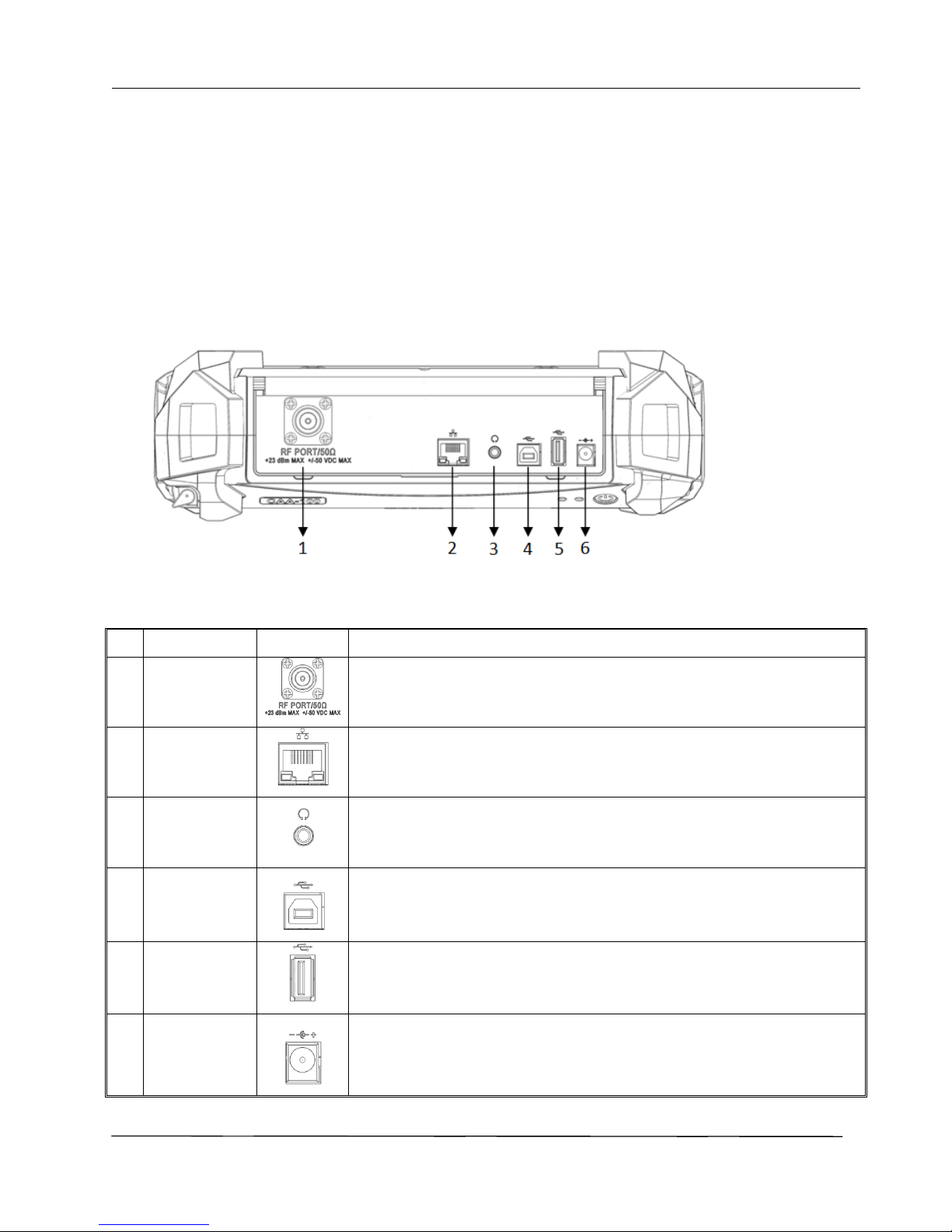
The head cover contains a variety of interface. A detailed description of the following
No.
Name
Icon
Function and Description
1
RF connector
To connect cable and antenna unit to be tested
2
RJ45 LAN
Reserved
3
Ear socket
Reserved
4
USB Device
port
To connect PC, then users can run special software to analyze and manage
measurement data
5
USB host port
To connect flash disk
6
Adapter socket
To connect external AC-DC adapter
Page 9
CAA-100 Series User’s manual
Shineway Technologies, Inc. - 3-
2.2 Front panel
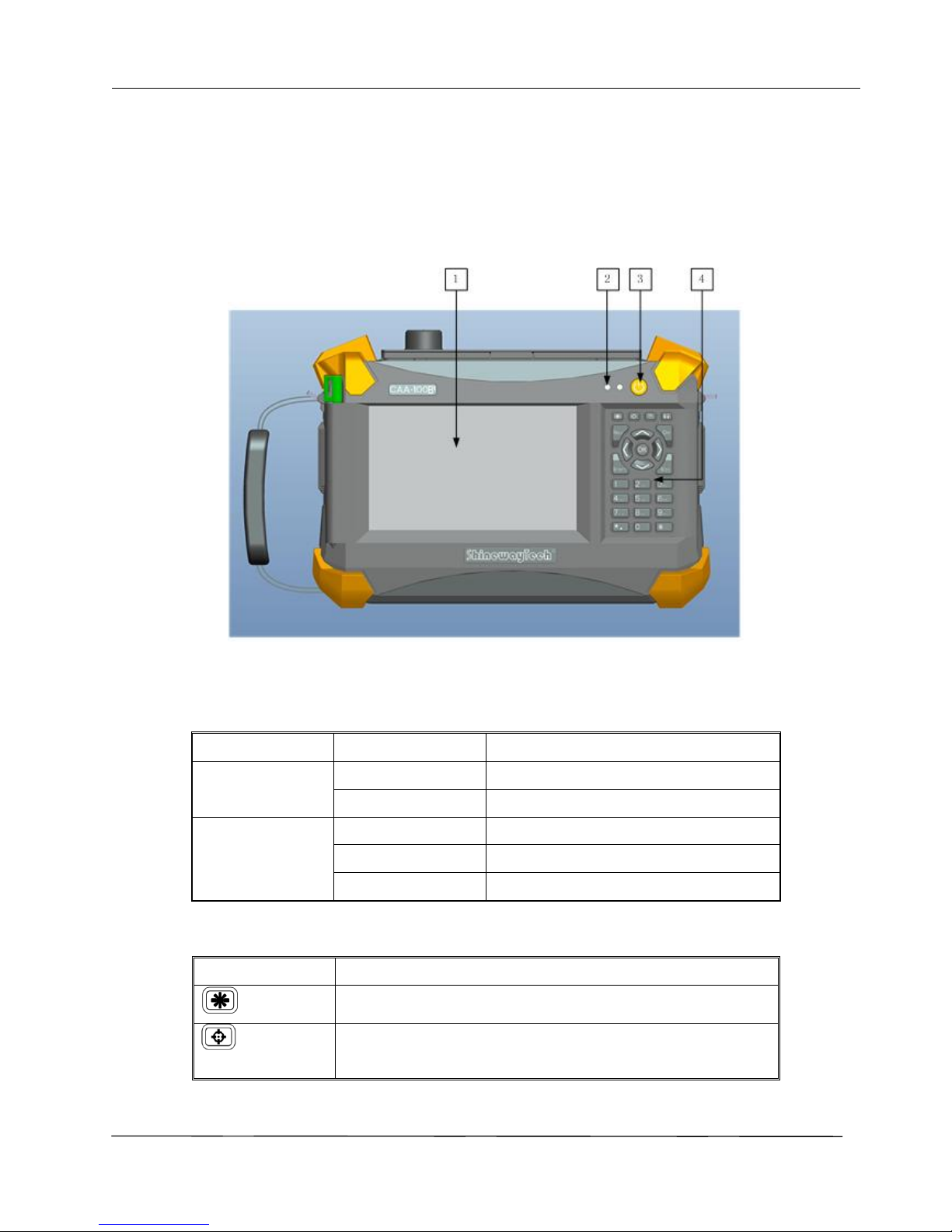
1. Screen display area;
2. indicator lights;
3. power button;
4. hard keyboard。
Note: Press the power button shortly to open the instrument, and press it for 2s to turn off the instrument;
Description for indicator lights:
Position
State
Meaning
Left
Red
Battery Charging…
green
Battery Charge fully
Right
Off
Power off
green
Power on
red
Measuring…
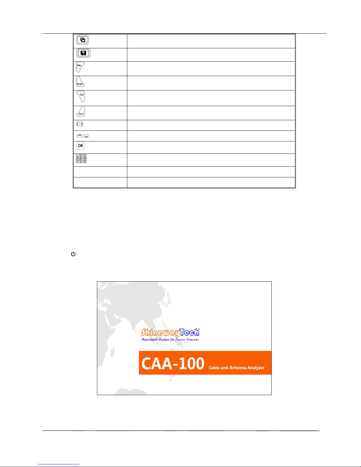
Description for hard keyboard:
Icon
function and description
Adjust the display screen brightness, there are four levels
Switch display mode (black and white, normal, night vision, and
high contrast)
Page 10
CAA-100 Series User’s manual
Shineway Technologies, Inc. - 4-
Preview, save the measurement picture
Save calibration and measurement curve
popup or down the right menu
Quick start measurement
Backspace
Return to the previous interface
left and right move marker line
Up and down move limit line
Enter key
Digital key, input 0-9
* key
decimal point
#key
Minus sign
3.User interface and menu instructions
3.1 Turn-on the instrument
Press , equipment will display the boot picture. During startup, the right light turns red, the system will
initialize DSP system, self check system state, etc. When main interface appear, the boot process end, the right light
turns green.
Page 11
CAA-100 Series User’s manual
Shineway Technologies, Inc. - 5-
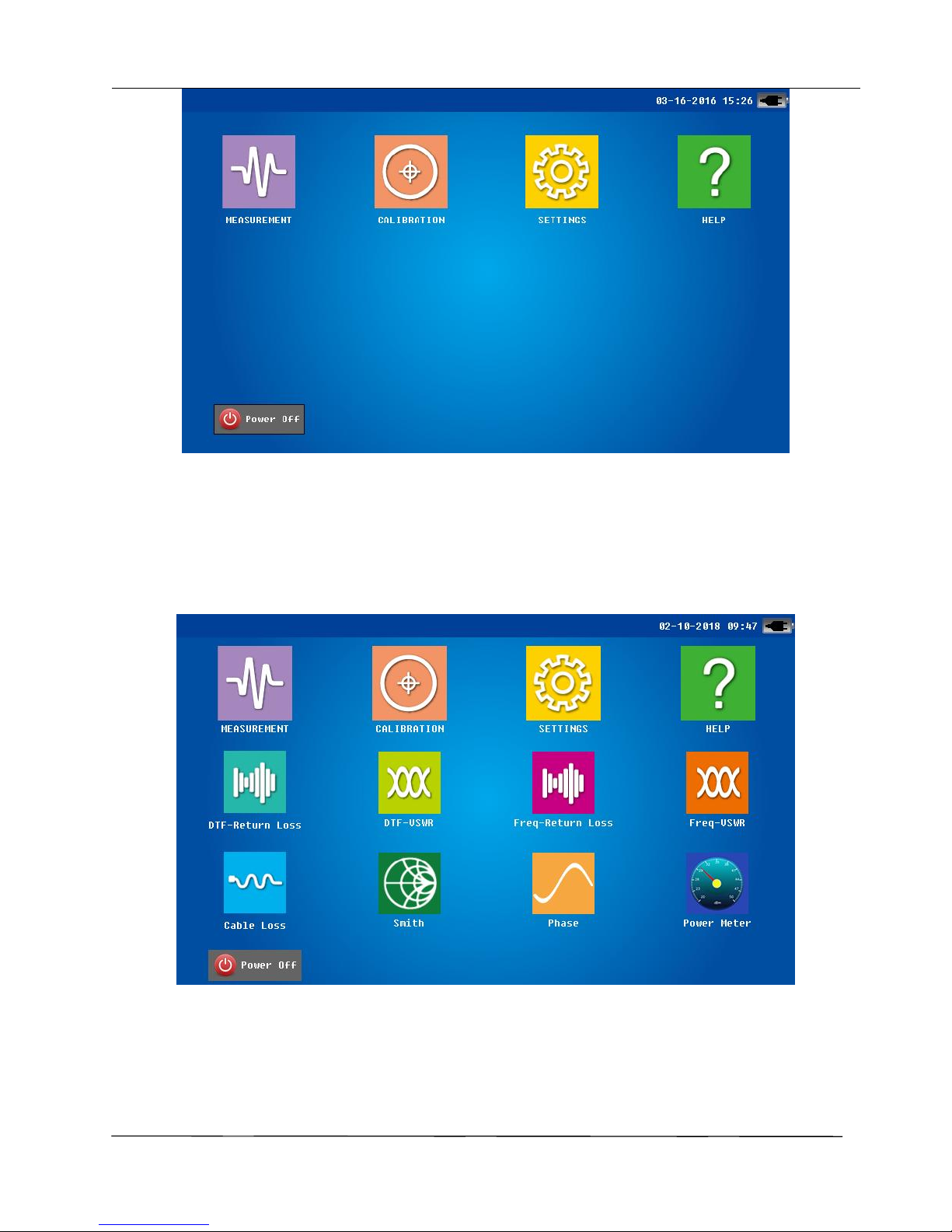
Main interface
3.2 Main interface
Click “MEASUREMENT” Icon,sub-icons appear, Corresponding to the five measurement modes: DTF(distance
fault )return loss, DTF-VSWR, Frequency return loss, Frequency-VSWR, cable loss, Smith, Phase and Power Meter.
Click the icon, the system will go into the corresponding measurement interface.
Note: Click other icons in the main interface (CALIBRATION, SETTINGS, HELP), system will enter the
corresponding operation interface.
3.3 Measurement Interface
Page 12
CAA-100 Series User’s manual
Shineway Technologies, Inc. - 6-
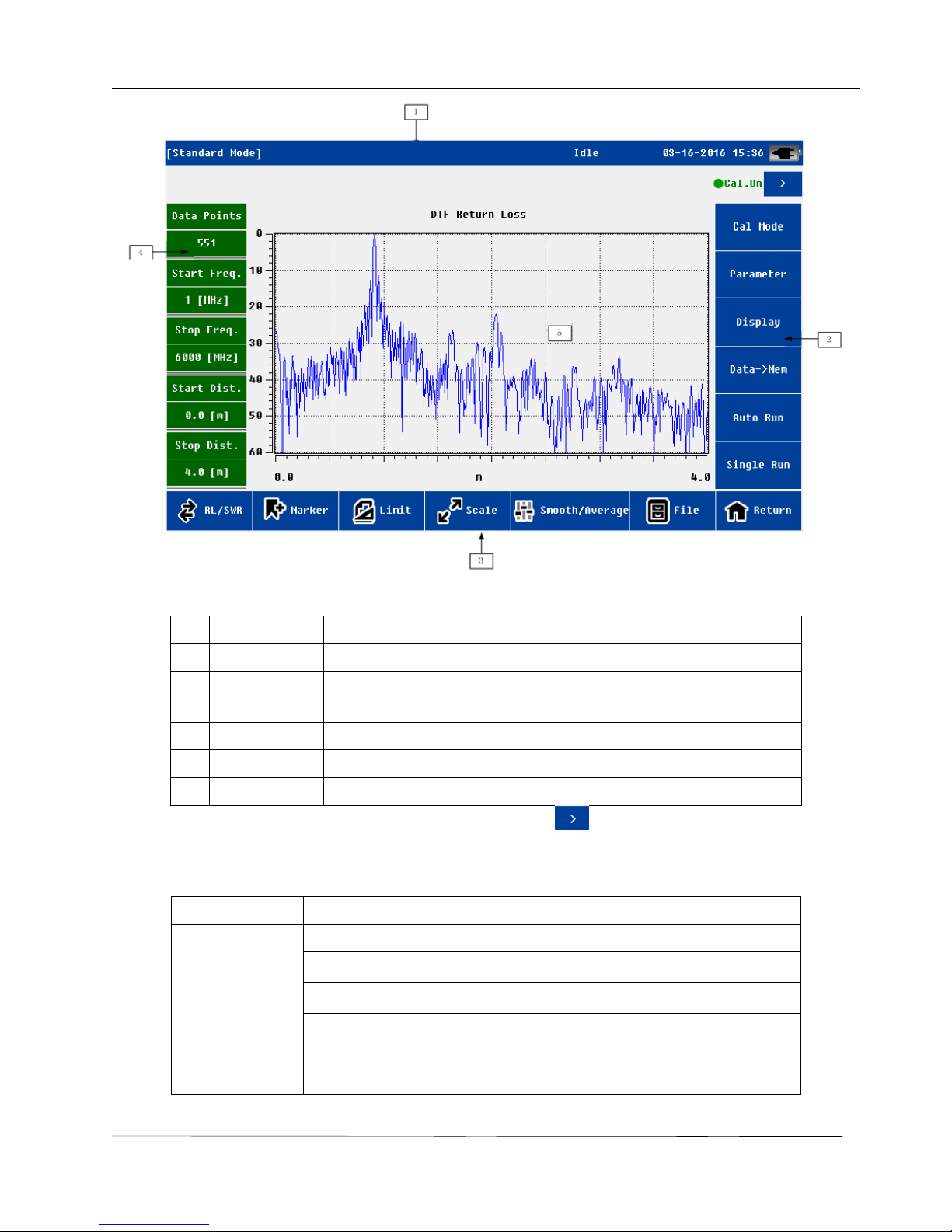
Measurement interface mainly consists of the following parts:
No.
Name
Position
Function and Description
1
status bar
Top
Display the system status and measurement information
2
function menu
Right
For details, see the later chapter
Note: If some menu are selected, this part may will refresh.
3
function menu
Bottom
For details see later chapter
4
Message bar
Left
Frequency, distance, measuring points etc.
5
Display area
Middle
For details see later chapter
If the user wants to zoom in the display area, can click the arrow or “Nav” key. Click again the area will
zoom out.
Detailed description:
Function
Function and Description
Status bar
Power management mode: standard and power saving mode
Measurement state:idle and measuring
Time:year/month/date/hour/minute
The adapter and battery state:
1. Connect an external adapter, without battery - display adapter icon;
2. Connect an external adapter, with battery charging - display
Page 13
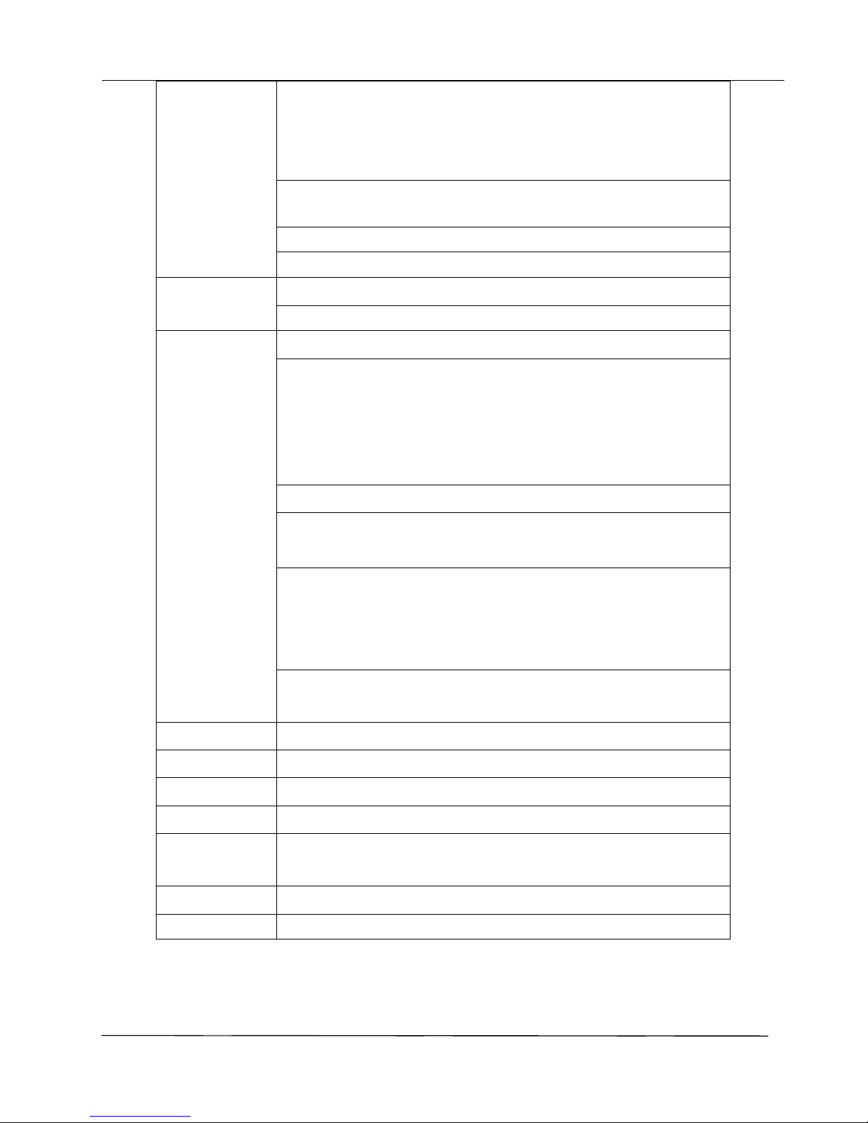
CAA-100 Series User’s manual
Shineway Technologies, Inc. - 7-
charging icon;
3. Connect an external adapter, with battery full - display adapter icon;
4. Without adapter, only battery - display battery icon, divided into 5
levels. If battery is low voltage system will alarm
Calibration state: (valid)On or (unvalid) off
Note: Only when calibration is valid(on), user can start measurement.
Marker information
Limit line information
Measurement
information
Measurement points:137、275、551、1103
Start and stop frequency and distance
Function menu 1
Cal mode:enter calibration interface
Parameter:enter parameter setting menu. If user in the freq-return loss/
freq-VSWR/cable loss measurement mode, it will go into frequency
parameter setting menu; If user in the DTF-return loss/DTF-VSWR
measurement mode ,it will go into DTF parameters menu, more
parameters and information will be included in this menu.
Display:For details see later chapter
Data-> Mem :Save current data to memory
Note:only one data can be save to the memory
Auto Run:Start continuous measurement, clicks again to stop.
Note: while measuring and Auto Run state is on, some functions are
prohibited. If users want to use these function again, need to click the
menu once again and check the state is off.
Single run:Start single measurement, the system enters the idle state after
measurement
Function menu 2
RL/SWR:fast switching between the return loss and VSWR measurement
Marker:For details see later chapter
Limit:For details see later chapter
Scale:For details see later chapter
Smooth/Average: turn on/off Smooth/Average function. User can
utilize these function to observe and analyze measurement dat.
File:For details see later chapter
Main display area
Display the measurement results and other information.
3.4 RF Power Meter Interface
Page 14
CAA-100 Series User’s manual
Shineway Technologies, Inc. - 8-
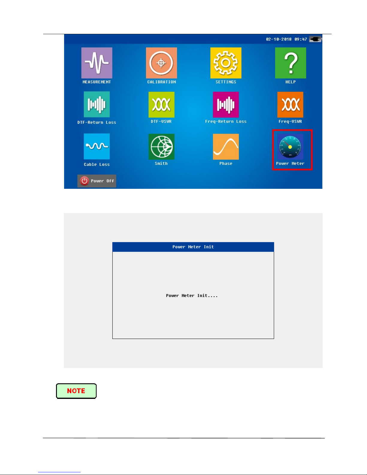
In the main interface, click Measurement—Power Meter coin, users will enter the RF Power Meter interface.
The steps and the interface are as shown below:
Users should connect the RF power meter to the unit first, and then click the coin to enter the
power meter interface.
Page 15
CAA-100 Series User’s manual
Shineway Technologies, Inc. - 9-
Users should quit the power meter interface, and then disconnect the power meter.
DPM-50AP Power Meter: Normal Mode: Forward Power, Reflected Power, Return Loss, VSWR, Peak Power,
Crest Factor, CCDF; Burst Mode: Burst Power, DutyCycle.
TPM-50A Power Meter: Normal Mode: Average Power, Peak Power, Crest Factor, CCDF; Burst Mode: Burst
Power, Peak Power, DutyCycle.
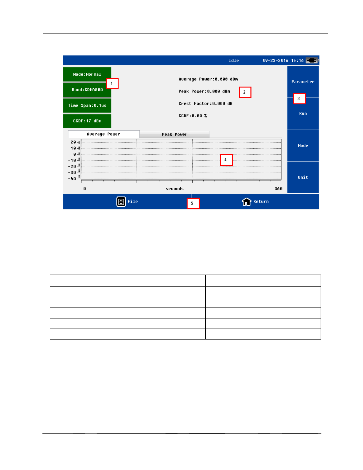
RF Power Meter interface is main including the followings:
No
Naming
Location
Description
1
Information status bar
Left up connector
Display parameter information
2
Test result display area
Up
RF power meter, etc.
3
Function menu
Right
Parameter setting, Run/Stop, Mode, Unit
4
Historical graph display area
Bottom
Display power meter in the current mode
5
File management and exit
Below
Files storage, import, delete; Image storage
3.4.1 Power Meter Setting
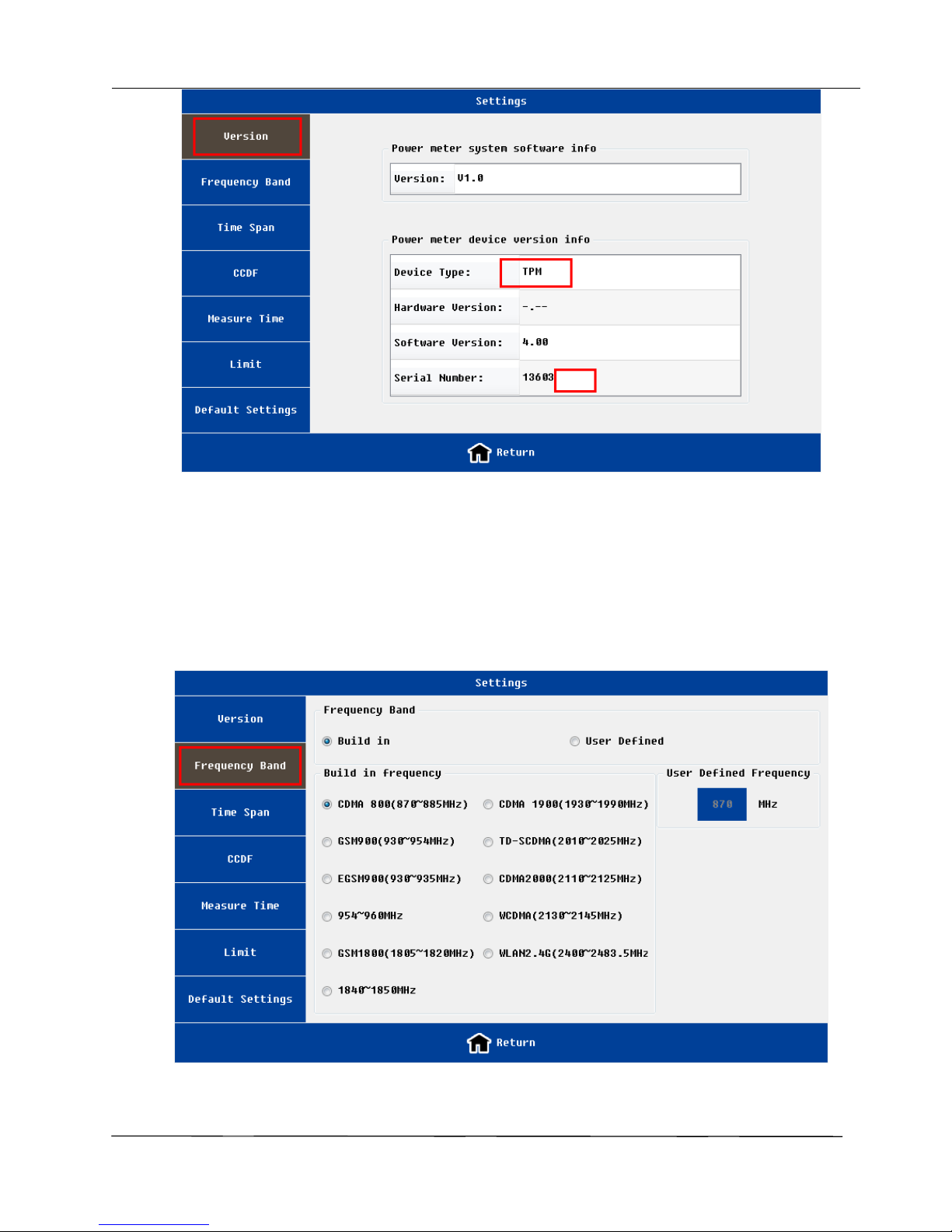
In setting menu, users can set parameters of power meter.
Version
This interface displays the power meter type, hardware and software version.
Page 16
CAA-100 Series User’s manual
Shineway Technologies, Inc. - 10-
Frequency Band
It is include build in frequency and user defined frequency. For the user defined frequency, users can input the
frequency range is below:
DPM-50AP Frequency range: 300M~4200M
TPM-50A Frequency range: 50M~4000M
Page 17
CAA-100 Series User’s manual
Shineway Technologies, Inc. - 11-
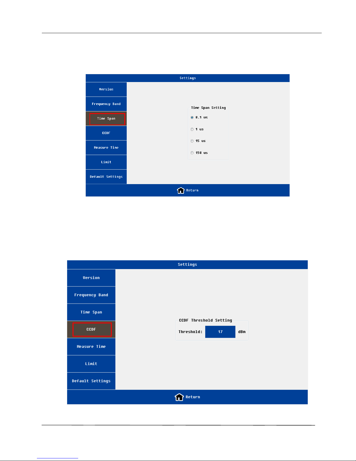
Time Span
For the time span setting, it is 0.1μs, 1μs,15μs and 150μs. Modulation signal modulation frequency is higher,
the time span should be smaller. For burst signals or pulse signals, the time span needs to be less than the minimum
pulse width.
CCDF Threshold
Before testing the CCDF, users should set the CCDF Threshold.
DPM-50AP CCDF Threshold : 17dBm~57dBm;
TPM-50AP CCDF Threshold : -40dBm~20dBm.
Page 18
CAA-100 Series User’s manual
Shineway Technologies, Inc. - 12-
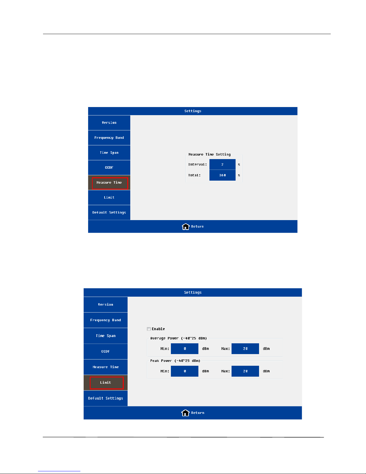
Measure Time
Users can set the interval measure time and the total measure time;
Interval : 1s – 60s;
Total : 2s – 7200s;
The total time should be longer than the interval time.
Limit
Users can set the limit power range and chose the Enable, and then the test result can be displayed in red color
to alarm.
Page 19
CAA-100 Series User’s manual
Shineway Technologies, Inc. - 13-
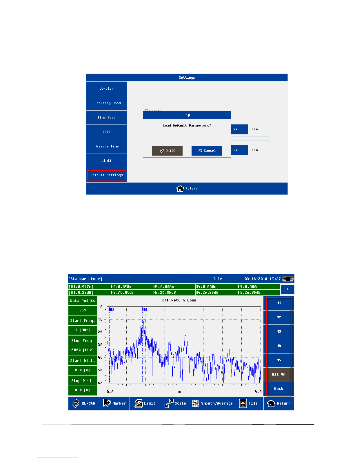
Default Setting
Users can load default parameters in this interface.
3.5 The function menu description
3.5.1 Marker
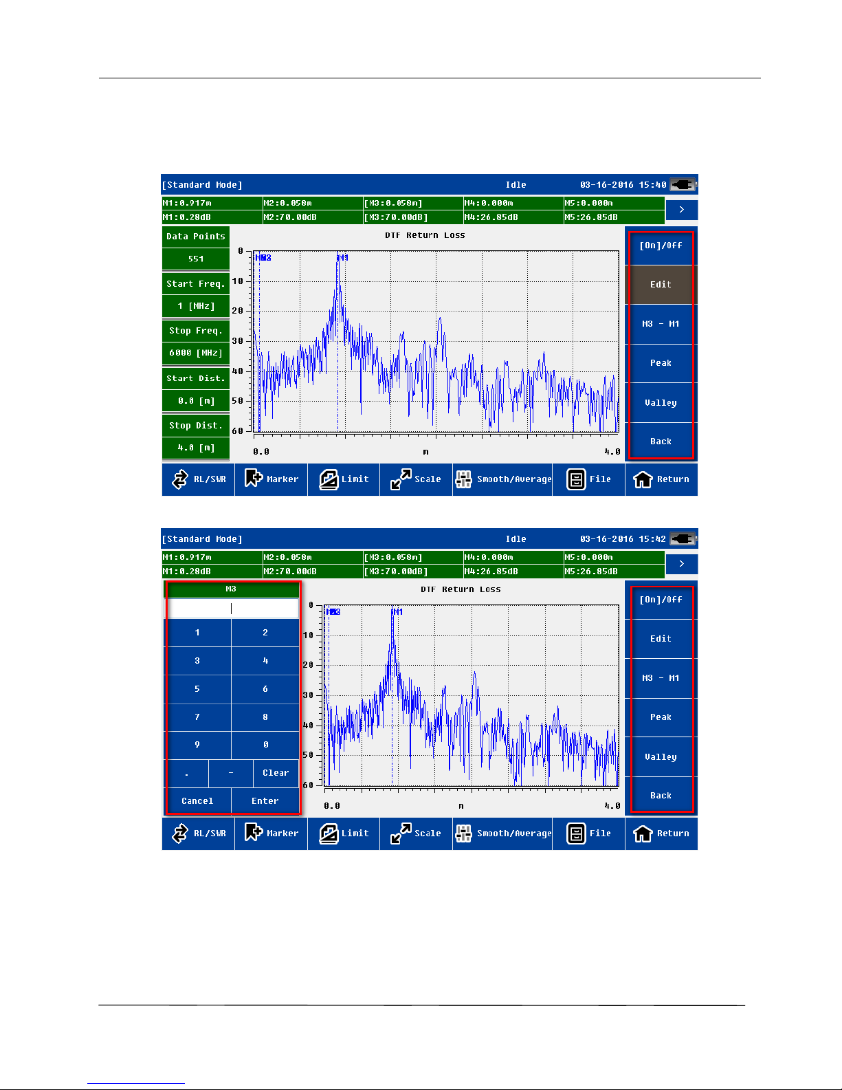
In all five measurement mode users can use mark function. The user click "marker" menu, new mark menu
will appear on the right side of screen.
Page 20
CAA-100 Series User’s manual
Shineway Technologies, Inc. - 14-
The system supports 5 marker lines(M1, M2, M3, M4, M5), each marker can be independent turn on/off and
edited. The user can also close all markers.
The user clicks on "MX", the MX marker automatically is activated. The status will be shown on the top status
bar. Users click on the "Edit" menu, the edit menu will show on the left side of the main display area.
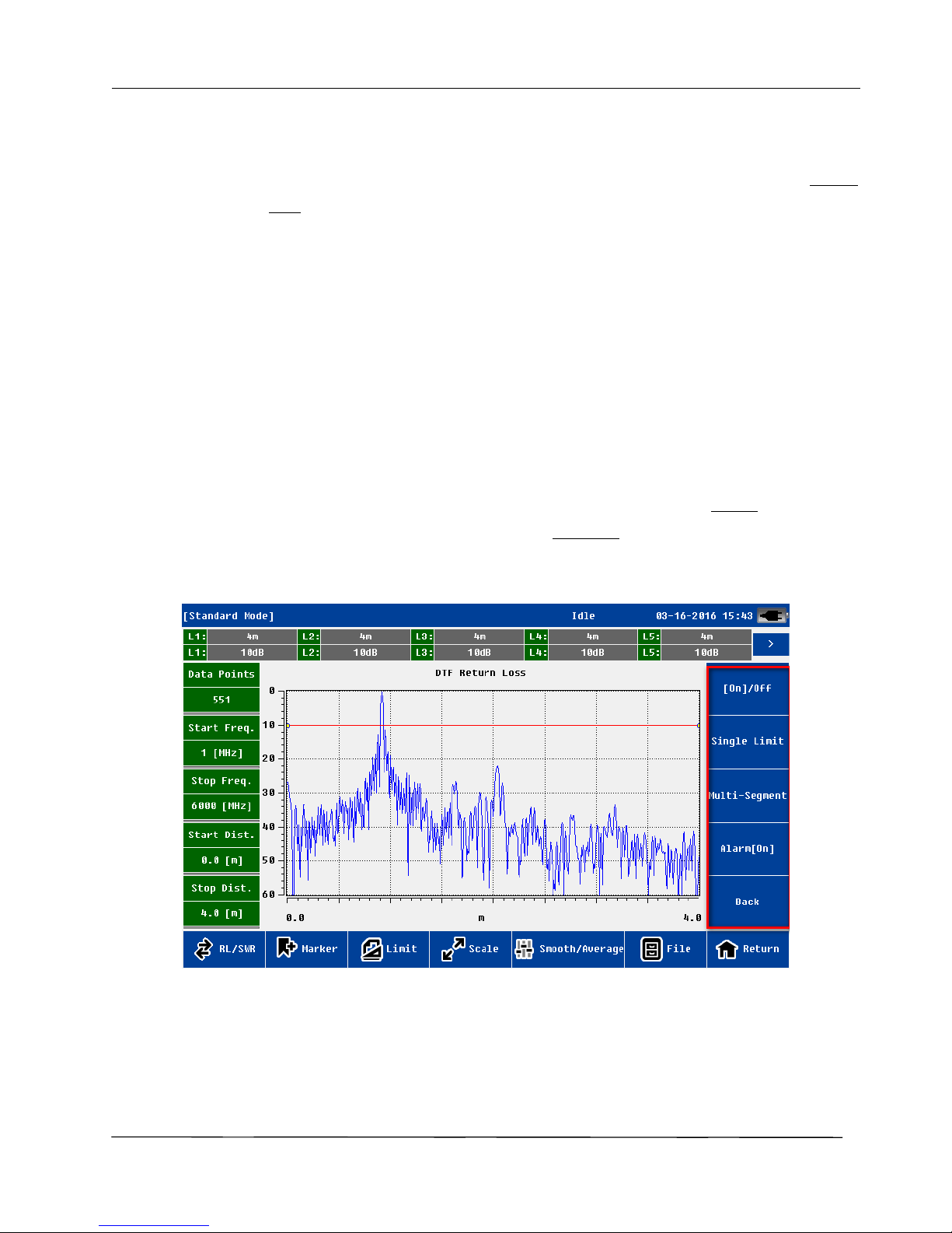
Marker setting menu
Marker setting menu
The user can define the position of marker line by the following ways:
The soft keyboard to enter digital value
Page 21
CAA-100 Series User’s manual
Shineway Technologies, Inc. - 15-
The hard keyboard to enter digital value
touch screen directly with touch pen to move and define the location
left and right arrow key of hard keyboard to fine adjust and define the location
After the location of the mark line is determined , users need to confirm the operation (soft keyboard "Enter"
key or hard keyboard "OK" key).
Users also can click on the "mark to the peak" or "mark to the valley" to determine the location of the mark
line
For M2~M5, the system also supports difference marker relative to M1 . users click on the "MX-M1" ,the
system will go into the difference marker mode. The status displayed in the status bar is the difference between X
and Y direction, i.e. (MX2~5-MX1; MY2~5-MY1).
3.5.2 Limit Line
In all five measurement mode users can use limit line function. The user click on the "limit "menu, the limit
menu will appear on the right side of screen. The user click on the “[On]/off” menu and activate this function. the
limit line status information will display on the top of the screen.
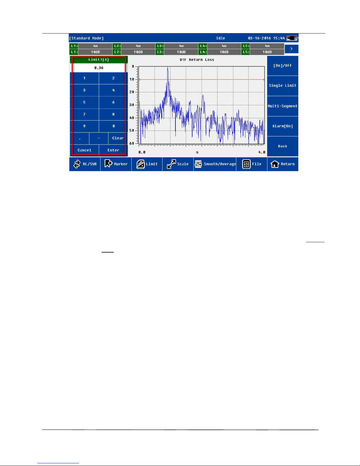
Limit menu
System supports single section and multi section limit line.
The user clicks on edit box of limit line status(x, y independently ), the new edit menu will pop-up on the left of
the screen.
Page 22
CAA-100 Series User’s manual
Shineway Technologies, Inc. - 16-
Limit setting menu
The user can define the limit line position by the following ways
The soft keyboard to enter digital value
The hard keyboard to enter digital value
touch screen directly with touch pen to move and define the location
Up and down arrow key of hard keyboard to fine adjust and define the location
After the location of the limit line is determined , users need to confirm the operation (soft keyboard "Enter"
key or hard keyboard "OK" key).
Users can also enable the limit line alarm function. If this function is enabled, once the measurement data
exceeds the limit line, limit line color will turn red (the default is green).
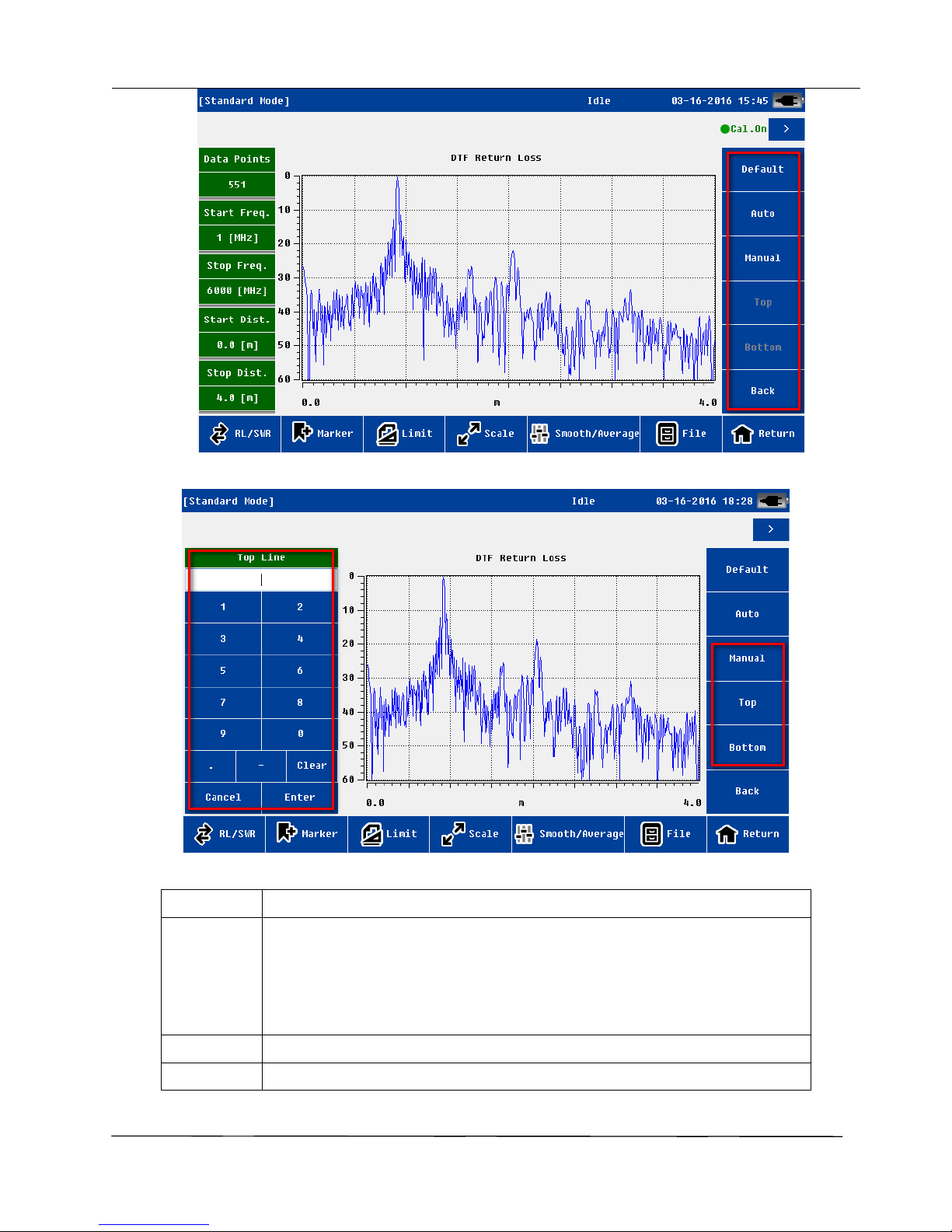
3.5.3 Scale
Scale function is mainly used to adjust the Y axis, convenient for users to view data.
Page 23
CAA-100 Series User’s manual
Shineway Technologies, Inc. - 17-
Scale menu
Manual scale setting menu
Name
function and description
Default
Y axis coordinate go back to the default value
Return Loss:0~60;
VSWR:1~65;
Cable Loss:0~30
Auto
Adjust Y axis automatically to adapt current measurement data
Manual
Users can edit upper and lower line of Y axis coordinate manually.
Page 24
CAA-100 Series User’s manual
Shineway Technologies, Inc. - 18-
The upper and lower coordinate can only be edited if “manual” menu is activated.
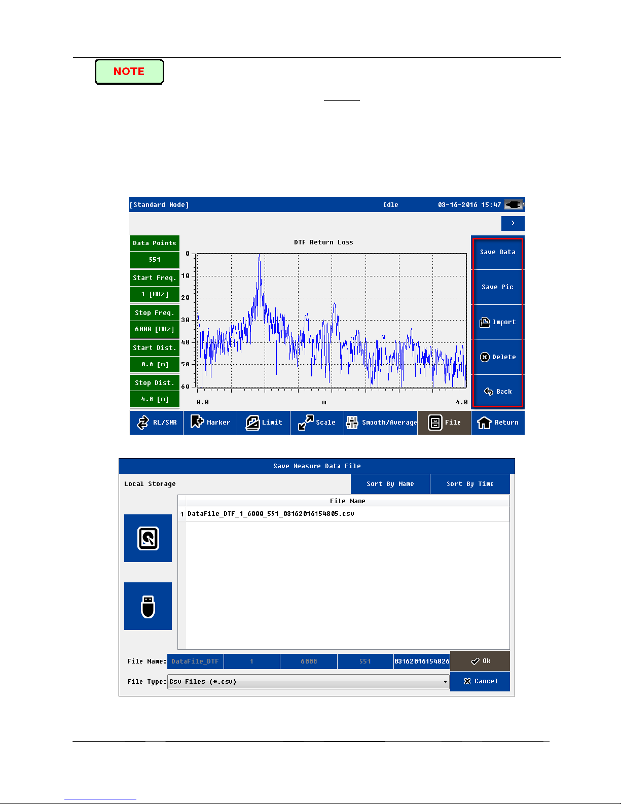
3.5.4 File
The user can save measurement data or picture to PC; also can recall measurement data from PC to CAA-100
Series . This function facilitate users to analyze the measurement data later.
File menu
Save file interface
Page 25
CAA-100 Series User’s manual
Shineway Technologies, Inc. - 19-
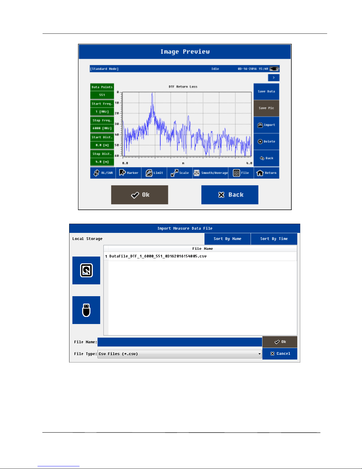
Image preview interface
File import interface
Page 26
CAA-100 Series User’s manual
Shineway Technologies, Inc. - 20-
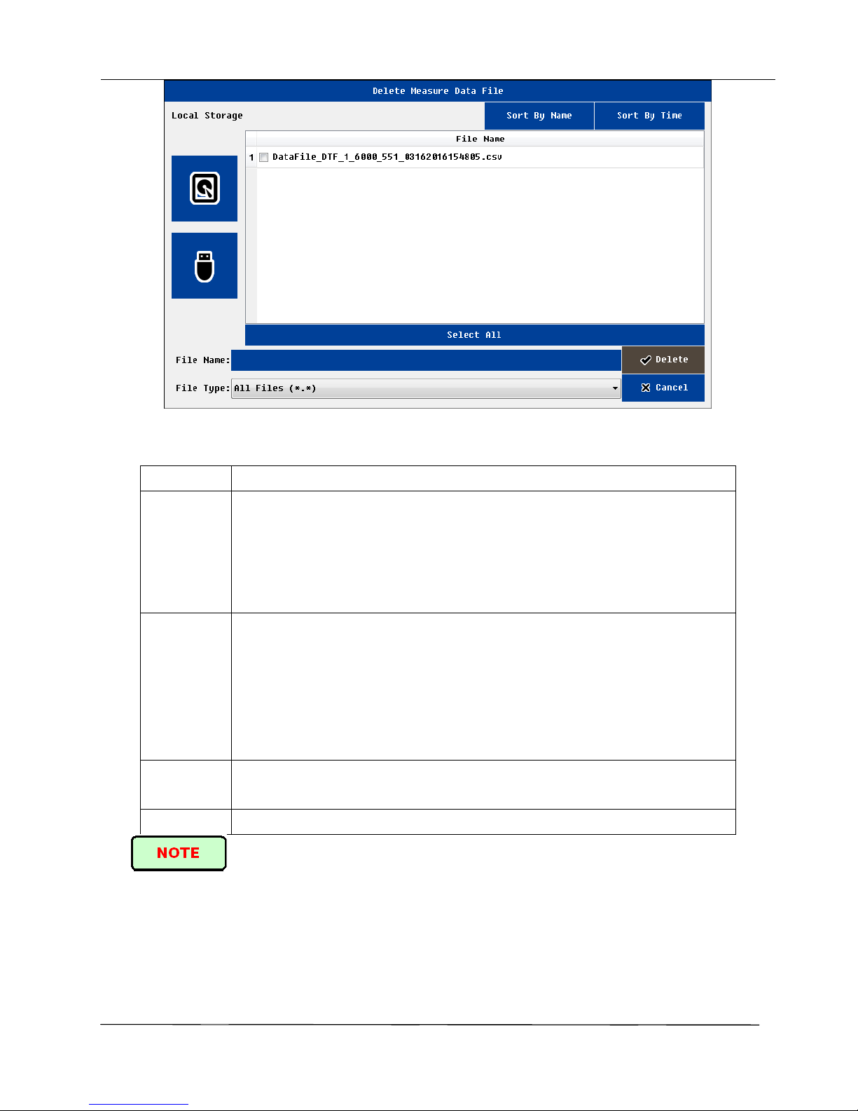
File delete interface
Name
Function and Description
Save Data
The default file type is .csv format
The default file name includes the measurement mode, frequency, measuring
points, the time information
users can choose to save in the local memory or external memory
Only support measurement and calibration data
Save Picture
The default file type is the.JPG format
The default file name includes the measurement mode, frequency, measuring
points, the time information
users can choose to save in the local memory or external memory
Only support measurement data
Screenshot only support the curve of measurement data
Recall Data
The target file can be stored in the local memory or external memory
Import file must be.csv type and the format must be correct
Delete
Delete the files
User must return to the superior interface before removing the external disk.
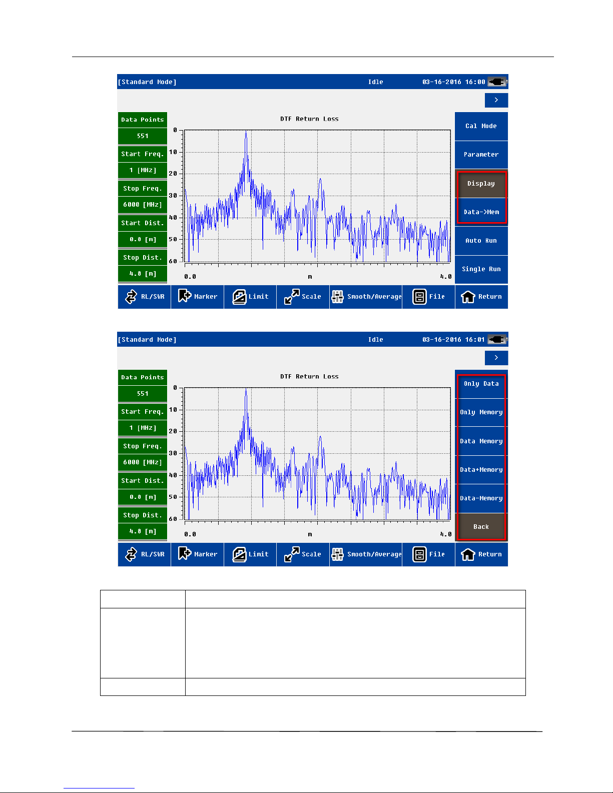
3.5.5 Display
The display menu is mainly used for data analysis. Users can save current data(either current measurement
Page 27
CAA-100 Series User’s manual
Shineway Technologies, Inc. - 21-
data or recalled history data ) to the memory , then compare the current measured data and memory data.
Display menu
Display setting menu
Name
function and description
Data->Mem
Save current data to memory
Note: Only one data can save
The data can be the current measurement data, can also be a historical
data. It can recall from local or external disk
Only Data
Display the current measurement data
Page 28
CAA-100 Series User’s manual
Shineway Technologies, Inc. - 22-
Only Memory
Display the memory data
Data & Memory
Display the current measuring data and memory data at the same time
Note: the format of two data must be same , such as the mode of
measurement, frequency, measuring points, the distance information etc.
Data + Memory
Display “the current measuring data plus the memory data”
Note: the format of two data must be same , such as the mode of
measurement, frequency, measuring points, the distance information etc.
Data - Memory
Display “the current measuring data - the memory data”
Note: the format of two data must be same , such as the mode of
measurement, frequency, measuring points, the distance information etc.
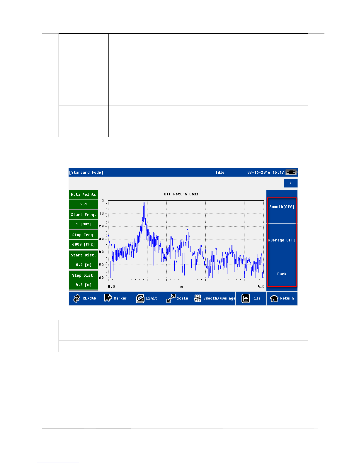
3.5.6 Average/Smooth
Average/Smooth menu
name
function and description
Smooth
For a single curve do smooth operation
Average
For 2 relative curve do average operation。
3.6 Calibration interface
Users need to calibrate before the measurement. For this unit, it has two methods : mechanical calibration
and electronic calibration.
Mechanical calibration is used T-type calibrator, the open short load (OSL) calibration. Users need to follow
Page 29
CAA-100 Series User’s manual
Shineway Technologies, Inc. - 23-
the instruction and connect open / short/50 Ohm load respectively to the RF port and do calibration. Finishing the
mechanical calibration, if users change frequency or the measurement point, this calibration will not effect and
users should recalibrate.
Electronic calibration is done with electronic calibrator, Flexcal calibration. Connect electronic calibrator and
data cable to the unit, click the Ecal coin, it will do the electronic calibration. Electronic calibration is default in the
whole frequency, and the measurement point is 551; Finished the electronic calibration, it will be effect whether
users change the frequency range and measurement point or not.
When users select the Flexcal, the calibration is default the whole frequency range calibration and the
measurement range is 551. When calibration is finished, changing the frequency range or measurement point will have
no effect on the calibration status.
Mechanical calibration can select the Flexcal or not. If select the Flexcal, calibration state will not be effect by
changing the frequency range or measurement point; if not, when users change the frequency range or measurement
point, users must do recalibration.
Electronic calibration is default to select the Flexcal.
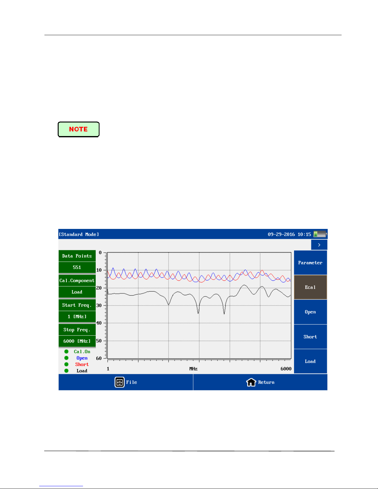
Calibration interface
The calibration interface is similar to measurement interface. On the left-top of screen including frequency
information, On the left-bottom of screen including calibration information.
The user can save current calibration data to the local or external disk, or Import history calibration data to
Page 30
CAA-100 Series User’s manual
Shineway Technologies, Inc. - 24-
CAA-100 Series.
Before calibration, the user need to set the correct parameters, Mainly refer to the frequency and
measurement points. The completion calibration, the corresponding curve will display on the screen. If calibration
is valid, the status on the left-bottom will become “cal On”. If calibration is invalid or unfinished, the status will be
“cal off”.
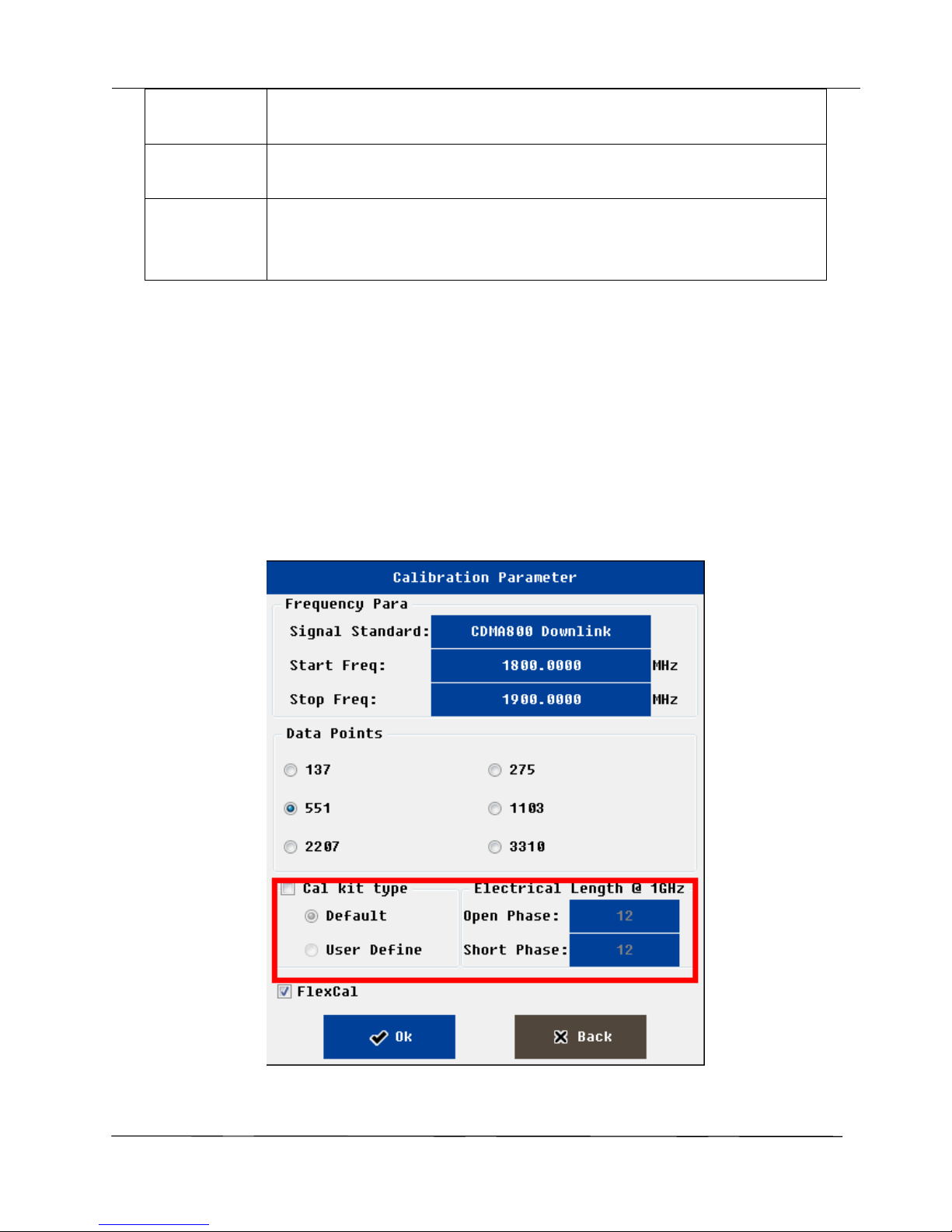
After the calibration, the user can return directly to the measurement interface for measurement.
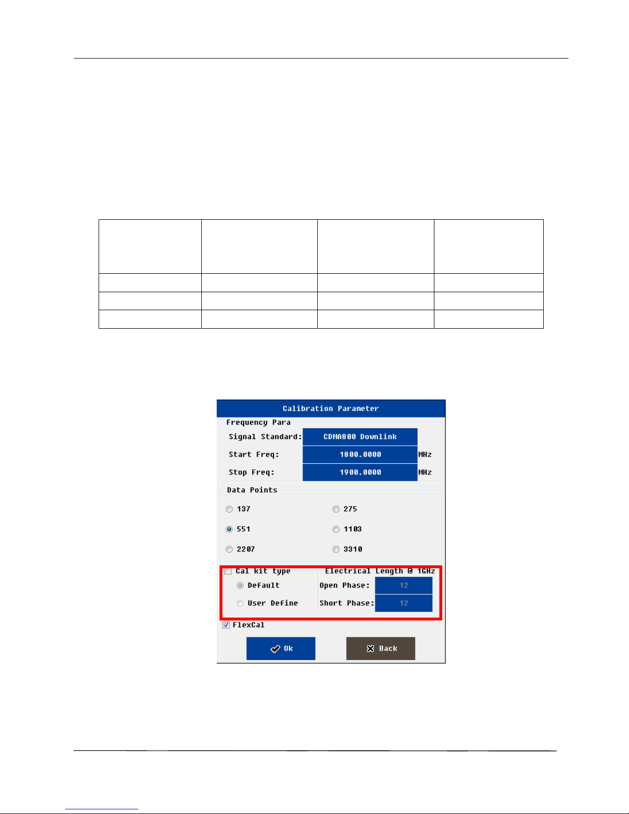
System support different calibration kit only if user know the exact electrical length of open/short load.
Users can input this parameters in the e parameter menu.
Is the electrical
length of open and
short cal kit same?
Is the exact electrical
length of open and short
cal kit known?
Return
Loss/VSWR/cable Loss
measurement
Phase/Impedenc-e
measurement
Yes
unknown
support
Do not support
Yes
know
support
Support
know
support
support
The return loss of 50 ohms cal kit need to be > 42.
The VSWR of open/short cal kit need to be >100.
If the user does not focus on phase and impedance characteristics, cal kit from other manufacturers can be
directly used (usually short and open cal kit have same electrical length).
Calibration setting menu
Note: the electric length is measured at 1GHz frequency, the unit is degree.
Page 31
CAA-100 Series User’s manual
Shineway Technologies, Inc. - 25-
3.7 System Settings Interface
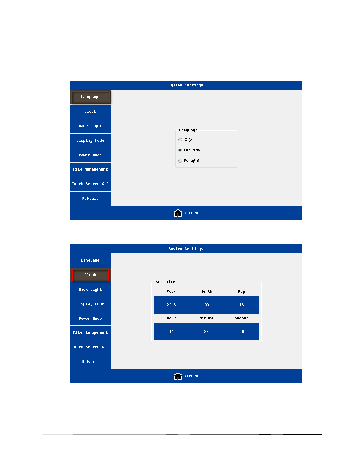
In the system settings interface, users can do all kinds of system configuration.
Language setting interface
Clock setting interface
Page 32
CAA-100 Series User’s manual
Shineway Technologies, Inc. - 26-
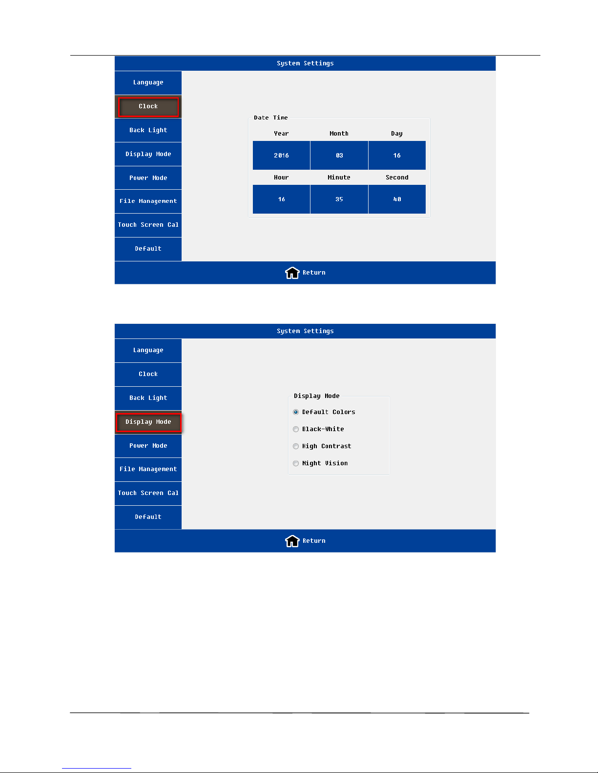
Back light setting interface
Display mode setting interface
Page 33
CAA-100 Series User’s manual
Shineway Technologies, Inc. - 27-
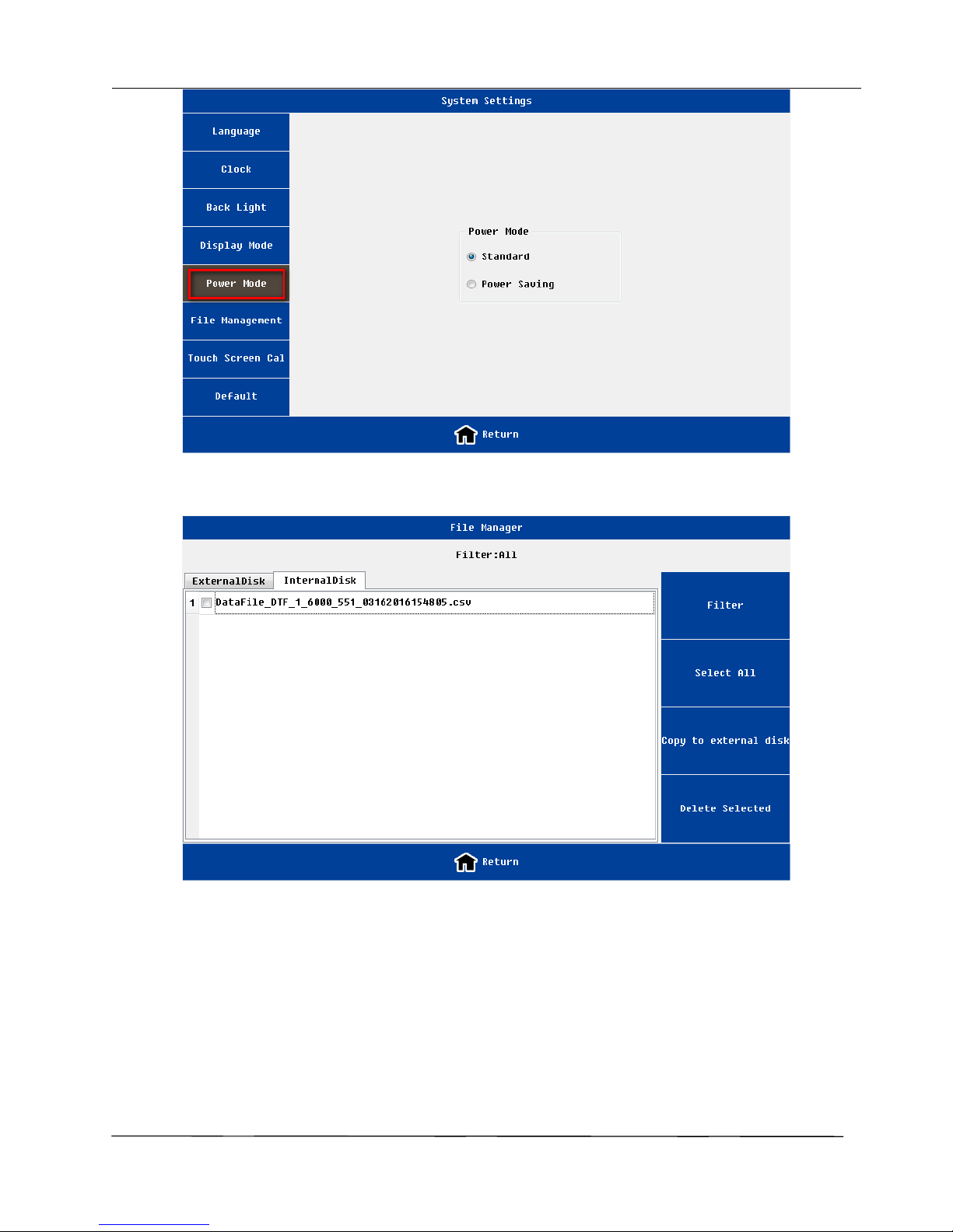
Power mode setting interface
Page 34
CAA-100 Series User’s manual
Shineway Technologies, Inc. - 28-
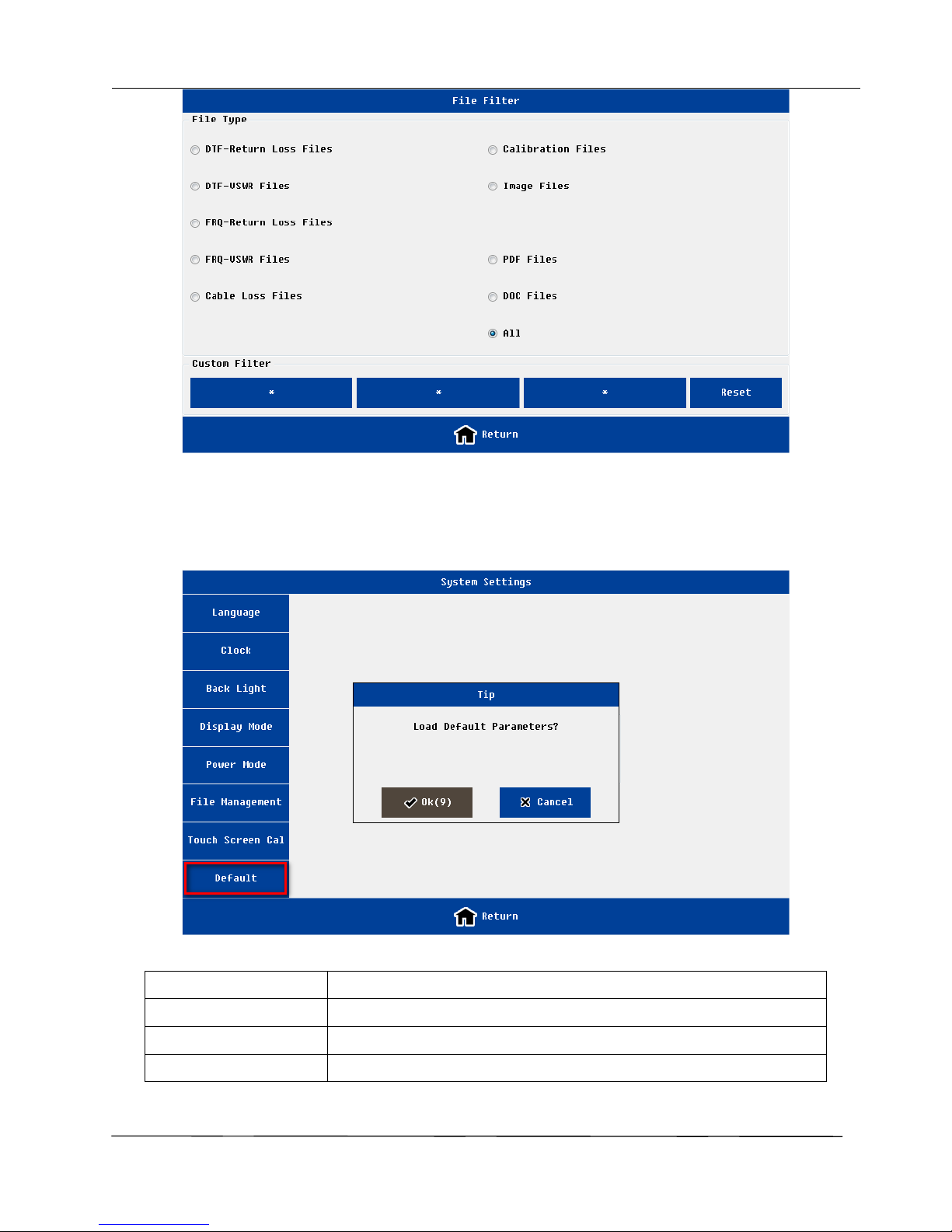
File manager interface
NOTE:
1) Please make sure that the external memory has been inserted before operating “File Management”;
2) User must return to the superior interface before removing the external disk to make sure files performed.
Load default setting interface
Name
function and description
Language
Support English /Chinese
Clock
year, month, date, hour, minute and second
Back Light
Support 4 levels brightness adjustment
Page 35
CAA-100 Series User’s manual
Shineway Technologies, Inc. - 29-
Display Mode
4 modes:
Default:
Black-white: used for printing
High-contrast:
Night vision: used in night environment
Fan Mode
Three modes: Auto; Always On; Always Off.
The default is Always On. If temperature higher than 45 degrees ,fan is
turned on; if below 35 degrees fan is turned off.
Power Mode
Two modes: standard modes(default); power saving mode
If working in the power saving mode, the relative RF circuits will be
power on until measurement . It can save power’s consumption and
protect circuits, but its disadvantage is the measurement time will be a
little long.
File management
For file management of both local disk and the external disk
Support file copy and delete functions
Support following file type :measurement data(.csv), measurement
image (.Jpg), calibration data (.csv)
Touch screen Cal
To calibrate the touch screen. Users Can exit by pushing any hard key
Default
Restore to default value
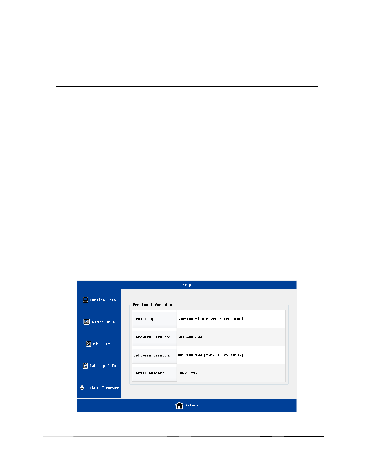
3.8 Help interface
Version information interface
Page 36
CAA-100 Series User’s manual
Shineway Technologies, Inc. - 30-
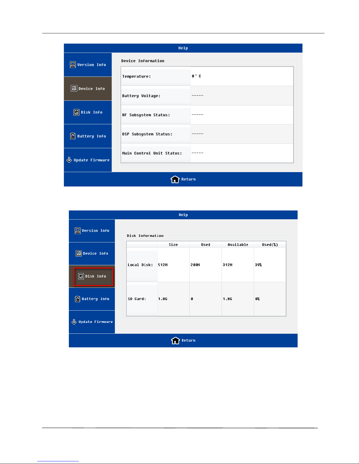
Device information interface
Disk information interface
Page 37
CAA-100 Series User’s manual
Shineway Technologies, Inc. - 31-
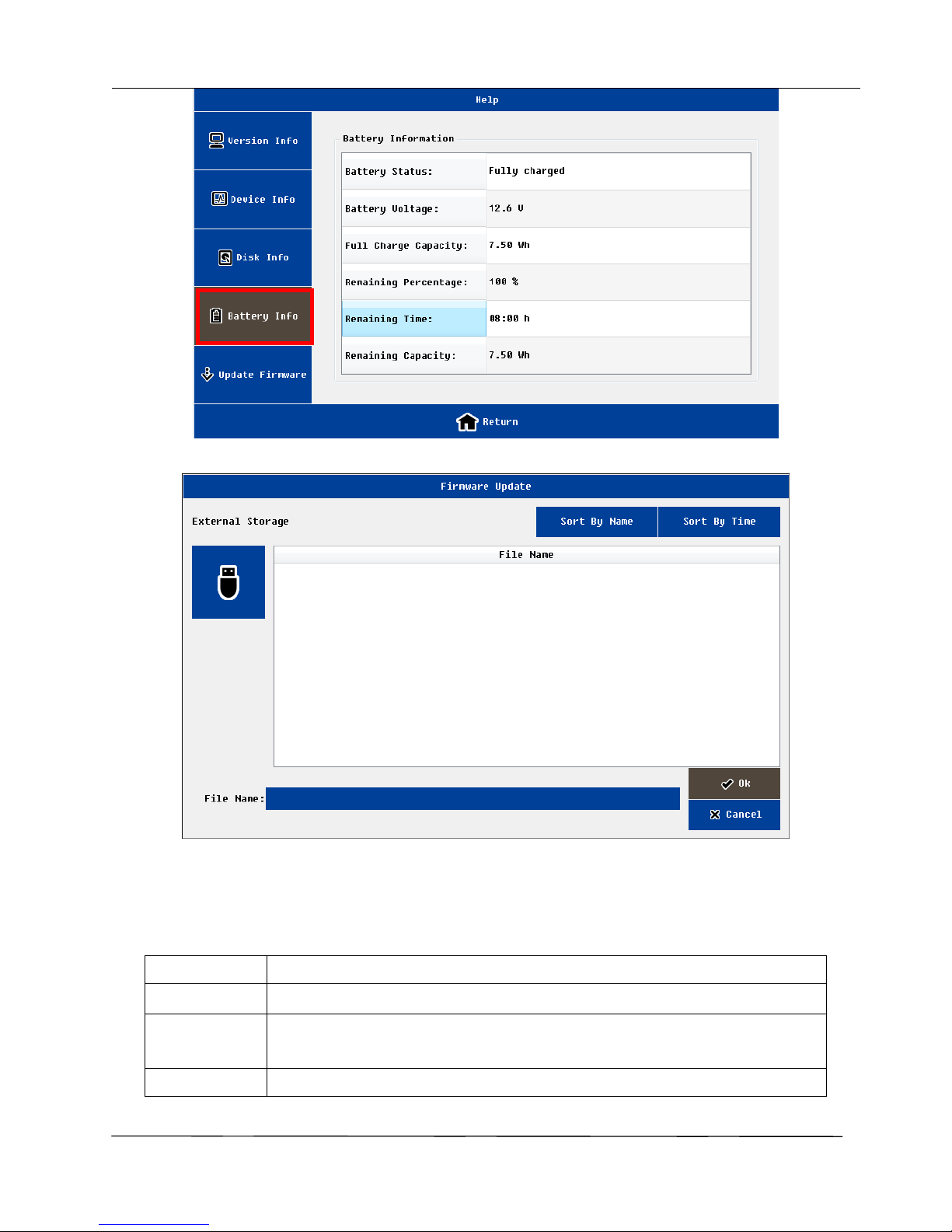
Battery information interface
Firmware update interface
On the help menu, the user can view a variety of instruments information; meanwhile users can upgrade the
firmware.
Name
function and description
Version Info
Includes:hardware version,software version,instrument serial number, etc.
Device Info
Includes: board temperature, battery voltage and instrument subsystems
statue, etc.
Includes: the information of local disk and a built-in SD card.
Page 38
CAA-100 Series User’s manual
Shineway Technologies, Inc. - 32-
Disk Info
Note: the local disk refer to flash memory, the different version of the program
will have different residual space
Battery Info
Showing the working status and residual power of the battery and other
information
Update
Firmware
The user insert the U-disk to the instrument, select the correct version file; the
instrument will automatically upgrade.
After the upgrade is complete, the instrument automatically restart.
4.Common operating instructions
4.1 Set frequency parameter
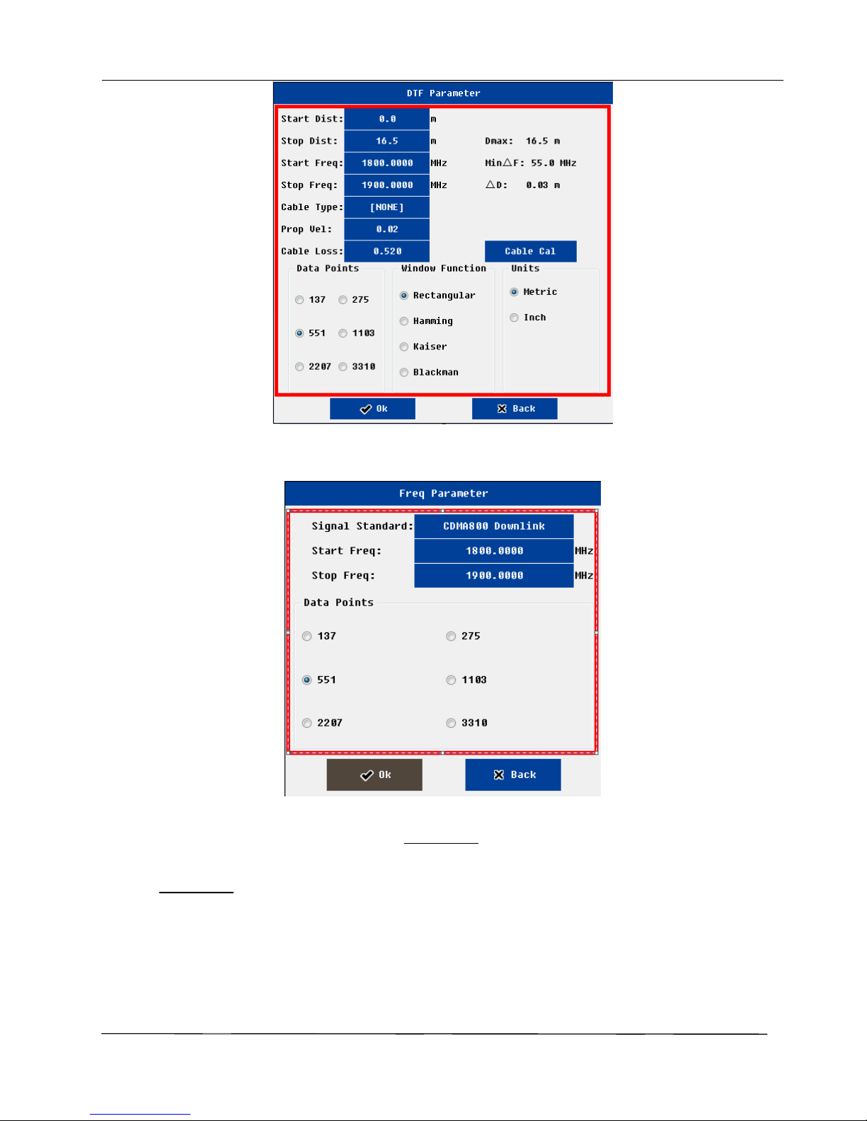
The user needs to properly set the frequency parameter before testing. In the following ways users can enter
the frequency setting interface.
Calibration setting interface
Page 39
CAA-100 Series User’s manual
Shineway Technologies, Inc. - 33-
DTF setting interface
Frequency setting interface
In the "calibration" interface, click on the "parameter" button
In the "frequency return loss" or "frequency VSWR" or "cable loss "measurement interface, click on the
"parameter" button
The user can also input frequency parameters in "DTF parameter setting" interface
After entering frequency setting interface, the user can set start frequency and stop frequency through the
following ways
Page 40
CAA-100 Series User’s manual
Shineway Technologies, Inc. - 34-
Select pre-defined Signal standard
Manual input frequency parameter
Users can click on edit box to edit the parameter of frequency , system will pop up the soft keyboard. The user
also can directly press the digital keys of hard keyboard .
The users need to select measurement points . System supports 4 options: 137,275,551,1103.
If the measurement point is set to 1103, compared with the set to 551, it will take about 2 times longer
measurement time. And so on.
The minimum frequency interval is 1MHz.
The start frequency range is 25~3999MHz;The stop frequency range is 26~4000MHz.
The user can modify the pre-defined signal standard through PC software .
4.2 Set DTF parameter
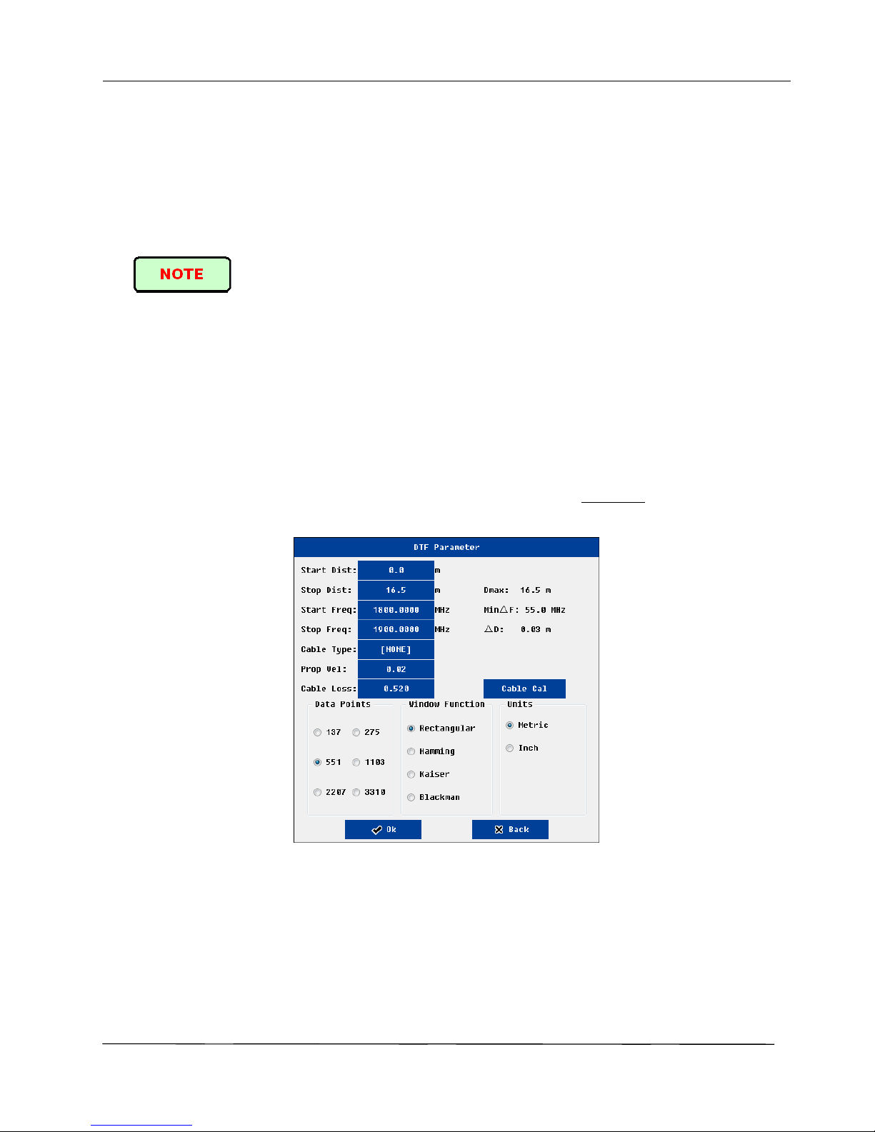
The user needs to properly set the DTF parameter before DTF testing. In the following ways users can enter
the DTF setting interface.
Enter the "DTF-return loss" or "DTF-VSWR" measurement interface, select "parameter" menu.
DTF setting interface
The user can complete the following functions at the DTF parameter setting interface
Enter frequency information and measure points
Enter the distance information
Enter the cable parameters
Select the window function
Set unit (support metric and Imperial)
Page 41
CAA-100 Series User’s manual
Shineway Technologies, Inc. - 35-
The user can modify the pre-defined cable parameters through PC software .
4.2.1 Set Distance parameter
Distance parameters need to satisfy the testing needs, but also associated with the following parameters
The operating frequency range (F1, F2)
The number of measured points (N)
Cable propagation velocity (Vp)
Once the user set the operating frequency, the number of measured points, cable propagation velocity, the
maximum allowed cable length (D
max
) has be decided.
12
1
**8^10*150*max
FF
VpND
For the convenience of users, the system will automatically display the relevant information (the maximum
allowed cable length: Dmax; resolution Δ D) in the upper right corner.
For example: N=551; Vp=0.85; F1=25MHz, F2=4000MHz. The corresponding Dmax is 17.64 meters, Δ D is
0.03 meters;
Do not change the frequency, if users want to increase the allowed cable length , can increase the number of
measuring points, the corresponding test time can also be longer
Due to the calculation of DTF, the minimum frequency interval is (N-1) *100kHz. If the measurement points is
551, corresponding minimum frequency interval is 55MHz.
The minimum distance interval is 1 meters (inch) or 1 feet (inch)
Start distance range is : 0~Max-1;stop distance range is 1~Dmax
4.2.2 Set Cable parameter
Users can manually input cable parameters (velocity; cable loss) or select the type of cable known.
the propagation velocity of electromagnetic wave in the cable is less than the vacuum speed (300M meters
/second). Propagation constant is 0.85, meaning that the actual propagation velocity of the electromagnetic wave
in the cable is the 0.85*300M meters / second.
When the user in the fault distance analysis, often want to know the return loss or VSWR of one exact
connector . At that position, the cable loss and connector return loss will be mixed together, systems need to
Page 42
CAA-100 Series User’s manual
Shineway Technologies, Inc. - 36-
remove cable loss impact in the calculation connector return loss. The unit of cable loss is dB/ meter.
Users can select cable from pre-defined cable list. Usually the cable loss will vary with frequency .System will
automatically calculate the cable parameters According to the cable parameters and working frequency.
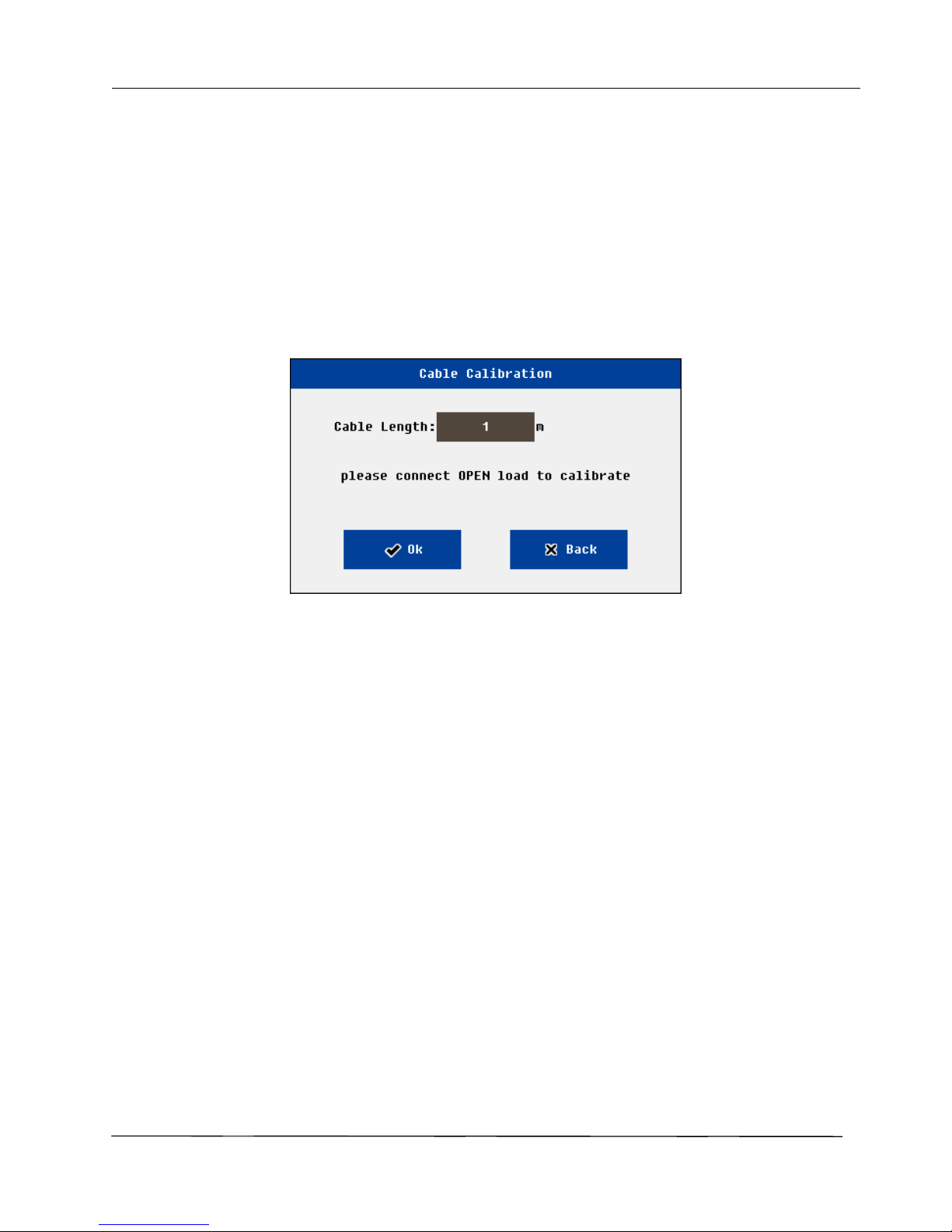
If the user does not know any cable information and parameters, but have a cable at hand, users can use the
system tools("cable" cal)to get these parameters.
Click on the "cable cal" button in the DTF parameter interface, system will pop up one window. Users enter the
measured actual length of cable (0.5~10 m); one end of the cable is connected to the RF port, the other end
connected to open load or connected to nothing;. Once the calibration is completed, the cable parameters will
automatically refresh in DTF parameter interface.
4.2.3 Set Window Function
In the distance to the fault analysis, if the location of the two connectors are close, because of the influence of
spectral leakage, two connectors will be influenced each other. If return loss of one connector is much smaller than
another one , most probably it will be lost and can’t be recognized. In this case users should choose to use the
window function.
System support four types window function: rectangle window, Hamming window, Keyser window, Blackman
window .
4.3 OSL Calibration
The user needs to confirm the system is in "calibration valid" state before a test.
Before one test, system need to know beforehand the 3 known load (open /short/50Ohm) test results. User
can import the previous calibration data; or do OSL mechanical calibration (Flexcal calibration)before test.
The user can enter the calibration interface by the following ways.
In the main interface, click on "calibration" mode icon
Page 43
CAA-100 Series User’s manual
Shineway Technologies, Inc. - 37-
In the measurement of interface, click on the button "cal mode"
The OSL calibration procedure is as follows,
Set the frequency parameter
Set up calibration parameters (optional)
Calibrate the first load
Connect the load to the RF ports, click on the corresponding button.
The system will pop up a small window, click on the “OK”.
System start calibration.
Once calibration is completed the screen will display the curve.
Calibrate other loads (Repeat the above steps)
If all calibration of three loads completed, the green "cal on" will shown at the lower left corner of the
screen.
Flexcal mechanical calibration is as the following step:
Set the frequency parameter and measurement point
Select the Flexcal calibration
Click open / short / load under calibration interface and select the corresponding calibrator to calibrate
If all calibration of three loads completed, the green "cal on" will shown at the lower left corner of the
screen.
Flexcal electronic calibration is as the following step:
Set the frequency parameter and measurement point
Select the Flexcal calibration
Connect the electronic calibrator and USB cable to the unit
Click the ECAL coin, and it will be automatic to calibrate
If all calibration of three loads completed, the green "cal on" will shown at the lower left corner of the
screen.
Users can directly calibrate at the RF port, also can calibrate with a high performance cable connected to RF
port. If the former, usually, the calibration curve of 50 ohm load will be significantly lower than the other two.
If calibration is completed, the user can start measurement .
The user can also select the file menu to save the calibration data in the local or external disk.
After the system boot, the default calibration data will be recent one.
The user clicks on the "file" menu, click "import", can recall previous calibration data. If the environment is
similar, the previous calibration data can be used directly.
For mechanical calibration, users need to re calibration if frequency changed or measurement points
increased.
For Flexcal calibration, users do not need to re calibration if frequency changed or measurement points
increased.
Page 44
CAA-100 Series User’s manual
Shineway Technologies, Inc. - 38-
Need to re calibration if temperature changes a lot
Do not need re calibration if measuring points reduced.
Do not need re calibration if distance, cable parameters, window function changed.
4.4 Freq-Return Loss, Freq-VSWR, Cable-Loss measurement
The measurement can be used to verify the power matching of the port or the loss of the cable .X axis
coordinate is frequency, Y axis coordinate are VSWR, or the return loss, or loss of cable separately.
In the following ways users can enter the measurement interface.
In the main interface, click on the "measurement" icon, and then click the corresponding icon
In the measurement interface, the user can do a variety of measuring operation.
Need to set proper frequency parameters before test
Need to confirm that the system is in "calibration valid" state before test
The minimum frequency interval is 1MHz
4.5 DTF-VSWR,DTF-Return Loss measurement
The measurement can be used to verify the power matching performance of different position of cable and
antenna system, then user know a certain position joint connection quality. X axis coordinate is distance, Y axis
coordinate is VSWR, or return loss
In the following ways users can enter the measurement interface.
In the main interface, click on the "measurement" icon, and then click the corresponding icon
At the measurement interface, the user can do a variety of measuring operation.
Need to set proper frequency ,distance, cable parameters and window function before test
Need to confirm that the system is in "calibration valid" state before test
The maximum measuring range and accuracy associated with frequency parameters, the propagation
velocity of cable
The minimum frequency interval :1M
The user can set the unit in the DTF parameters window units (metric and Imperial)
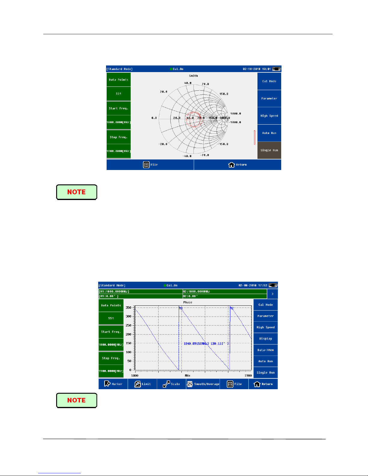
4.6 Smith Chart
The Smith Chart is a graphical tool for plotting impedance data versus frequency. It converts the measured
reflection coefficient data into impedance data and displays it in a manner that makes the Smith Chart a useful
Page 45
CAA-100 Series User’s manual
Shineway Technologies, Inc. - 39-
tool for determining and tuning input match. For the testing result, ZL is impedance, r is phase, RL is return loss
and VSWR is voltage standing wave ratio.
In the main interface, click [Measurement]----[Smith], users can enter the Smith Chart interface.
Set parameter first and make sure the it is in Cal.On status, before measurement.
4.7 Phase
Phase can display the phase of the reflection measurements at Port.
X is Frequency; Y is Phase.
In the main interface, click [Measurement]----[Phase], users can enter the Phase interface.
Set parameter first and make sure the it is in Cal.On status, before measurement.
Page 46

CAA-100 Series User’s manual
Shineway Technologies, Inc. - 40 -
5 warranty information
5.1 the warranty period
For all ShinewayTech products, due to the fault caused by the material or
production reasons, the company provide free warranty for one year from
product delivery. In the warranty period, any failure of the product can provide
a warranty or replaced by the company, but in any case, the company to assume
the responsibility of all limits the original price range in the purchase of the product.
This warranty does not include the company providing products accessories or
selected parts.
5.2 Exclusions
The warranty on your equipment shall not apply to defects resulting from the
following:
Unauthorized repair or modification
Misuse, negligence, or accident
Shineway Technologies, Inc. reserves the right to make changes to any of its products
at any time without having to replace or change previously purchased units.
5.3 Warranty Registration
A warranty registration card is included with the original shipment of equipment.
Please take a few moments to fill out the card and mail or fax it to the local Customer
Service Center of Shineway Technologies, Inc. to ensure proper initiation of your warranty
term and scope of your warranty.
5.4 Returning Instruments
To return instrument for reasons of yearly calibration or other, please contact the
Page 47

CAA-100 Series User’s manual
Shineway Technologies, Inc. - 41 -
local Customer Service Center of Shineway Technologies, Inc. to obtain additional
information and a RMA# (Return Materials Authorization number). And describe briefly
reasons for the return of the equipment, to allow us offer you more efficient service.
5.5 Contacting Customer Service
Please check our web site (www.shinewaytech.com) for updates to this manual and
additional application information. If you need technical or sales support, please contact
local Shineway Technologies Customer Service.
Shineway Technologies (China), Inc.:
Address: Floor 7, Zhongtai Plaza, No.14 Shuangqing Rd.
Haidian District, Beijing, P.R.China
Postal code: 100085
Tel: +86-10-62953388
Fax: +86-10-62958572
Email: [email protected]
WEB: www.shinewaytech.com
Page 48

CAA-100 Series User’s manual
Shineway Technologies, Inc. - 42 -
THANK YOU FOR CHOOSING
SHINEWAY TECHNOLOGIES!
 Loading...