


Shindengen Electric Manufacturing Company Ltd MTD1110 Datasheet
SHINDENGEN
Stepping Motor Driver ICs
MTD1110
FEATURES
●Constant-current chopping function
(Off time fixed, self-oscillation)
●4-phase input
(with inhibit for simultaneously turn ON)
●An ENABLE function is provided
●Built-in overheating protection
(Alarm + shutdown)
●Built-in flywheel diodes
RATINGS
MTD Series
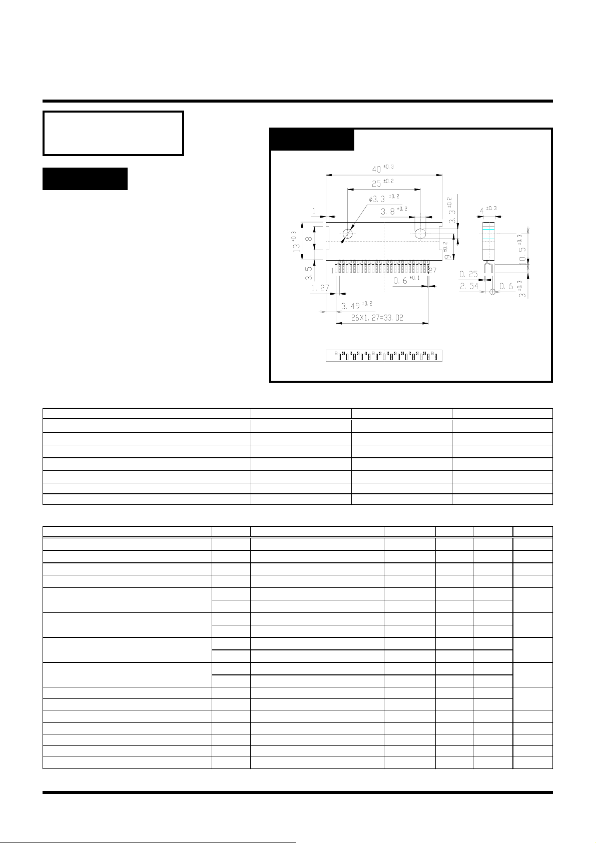
OUTLINE DIMENSIONS
Case : ZIP-27
(Unit : mm)
●Absolute Maximum Ratings Ta=25℃
Item Symbol Ratings Unit
Output Voltage
Output Current
Logic Supply Voltage
Logic Input Voltage
Total Power Dissipation
Junction Temperature
Storage Temperature
●Electrical Characteristics (Ta=25℃)
Item Symbol
Output Saturation Voltage
Output Leakage Current
Logic Supply Current(Standby)
Logic Supply Current(All Circuit ON)
Input High Voltage
Input Low Voltage
Logic High Input Current
Logic Low Input Current
Reference Input Current
Input Current(Current Sensor)
Maximum Sensing Voltage
Thermal Alarm Cutoff Current
Thermal Alarm Output Current
Thermal Alarm Temperature
Thermal Shutdown Temperature
VCE(sat)
I
CER
ICC(OFF)
ICC(ON)
V
INH
V
ENAH
V
INL
V
ENAL
l
INH
l
ENAH
l
INL
l
ENAL
Iref
Isense
VS(max.)
Iralm
Ialm
Talm
T
TSD
V
CEO(SUS)
I
V
V
P
O
CC
IN
T
80 V
2A
0~7V
0~V
CC
5W
Tj 150 ℃
Tstg -40~150 ℃
Test Conditions min. typ.
Io=1.5A 1.11.4
V
=80V 10
CER
VCC=5V,V
VCC=5V,V
VCC = 5V 2.7 Vcc
VCC = 5V 2.7 Vcc
VCC = 5V GND 1.0
VCC = 5V GND 1.0
VCC = 5V,VIN=5V 10
VCC = 5V,V
VCC = 5V,VIN=0V -10 -50
VCC = 5V,V
VCC=5V,Vref=0V -1 -50
VCC=5V,VS=0V -1 -50
VCC=5V 1.0
VCC=5V,Valm=5V 10
VCC=5V,Valm=0.5V 2
="H" 20 40
ENA
="L" 40 60
ENA
=5V 10
ENA
=0V -10-100
ENA
125
150
max. Unit
V
V
μA
mA
mA
V
V
μA
μA
μA
V
μA
mA
℃
℃
Copyright & Copy;2000 Shindengen Electric Mfg.Co.Ltd
Stepping Motor Driver ICs
MTD1110
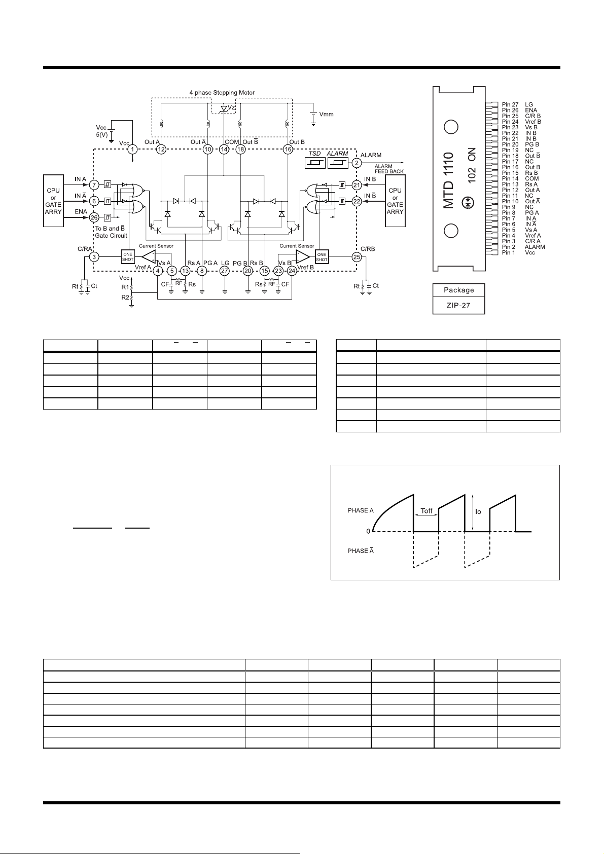
● Equivalent Circuit・Basic Application Circuit ●Pin Assignment
●True Table
ENA IN A or B IN A or B Out A or B Out A or B
LLLOFFOFF
LLHOFFON
LHLONOFF
LHHOFFOFF
H
××
× : don't care
OFF OFF
●Setting of Output Current and Fixed Off Time
Fig.1 shows constant current chopping wave form.
○Output Current setting
Io =
○Fixed Off Time Setting
R2
R1+R2
・
Vcc
Rs
Toff=0.69・Ct・Rt
●Recommended Parts Value
Symbol Recommended Value Unit
Rs 0.68 Ω
RF 1 kΩ
CF 3300 pF
Rt 8.2 kΩ
Ct 3300 pF
Vz Vmm×1.2~1.5 V
R1+R2 <10kΩ
Fig.1 Constant current wave form (Motor current)
●Recommended Operating Conditions (Ta=25℃)
Item Symbol min. typ. max. Unit
Motor Supply Voltage
Output Voltage
Output Current
Output Emitter Voltage
Logic Supply Voltage
Chopping Frequency
Operating Temperature
Vmm
V
V
V
fchop
Top
Copyright & Copy;2000 Shindengen Electric Mfg.Co.Ltd
OUT
I
O
E
CC
32
70
1.5
1.0
4.75 5.25
20 27
-25 120
V
V
A
V
V
kHz
℃