

Shindengen Electric Manufacturing Company Ltd MA3810 Datasheet
SHINDENGEN
g
g
Power Switching Regulators
MA3810
RATINGS
MA3000 Series
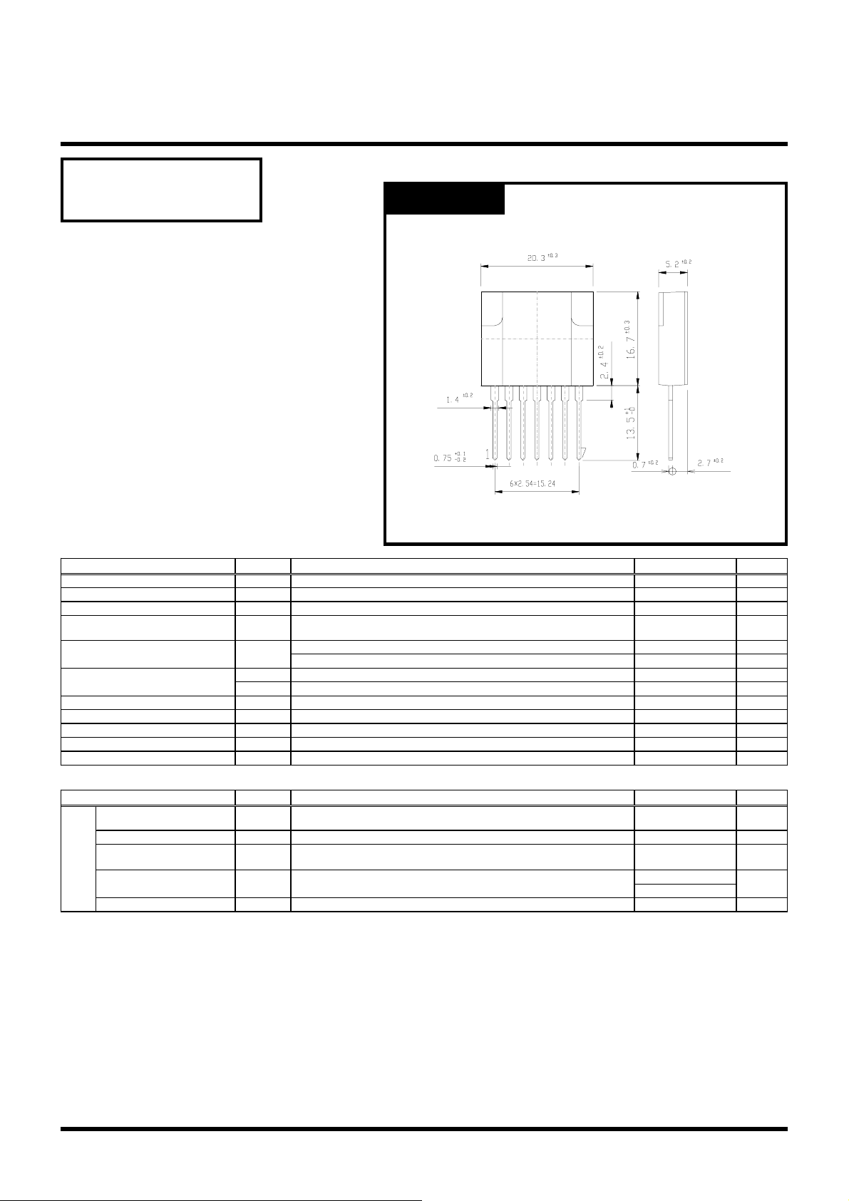
OUTLINE DIMENSIONS
Case : MA7
Unit : mm
●Absolute Maximum Ratings
Storage Temperature
Item
Operating Temperature
Junction Temperature
Peak Input Voltage
Input Current
Maximum Power Dissipation
Dielectric Strength
Insulation Resistance Terminals To Case 500VDC
Max Voltage ④ to ⑦
Max Current ⑥ to ④
Max Current ⑤ to ④
Symbol Unit
Tstg ℃
Top ℃
Tj ℃
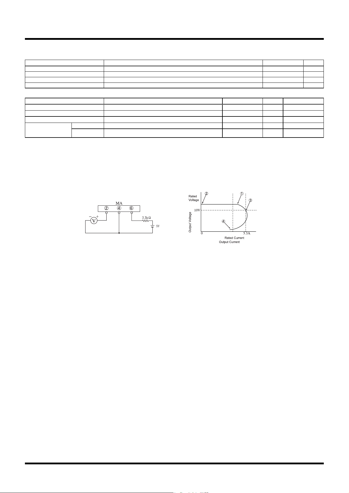
②+,④-,Fig.1 is Measurement Circuit of Peak Input Voltage Vin and Collector
Cutoff Current I
Vin V
DC ②+,④-
Pulse ②+,④- Pulse Width 150μs MAX, Duty1/2, Sawtooth Wave, Peak Value.
Iin
P
Ta=25℃
D
P
Heatsink Tc=100℃
D
Terminals To Case AC 1 min
Vdis
V④・⑦
I⑥・④
I⑤・④
④+,⑦⑥+,④- (Peak)Duty Max 3/5
⑤+,④- (Q2 Collector Current)
CEX
.
●Electrical Characteristics (Tc=25℃)
Item Conditions
Collector Cutoff Current
Q1
DC Current Gain
Collector to Emitter Saturation
Voltage
Driving Saturation Voltage
Thermal Resistance
Symbol Unit
I
CEX
h
FE
VCE(sat)
VD(sat)
θjc
VCE=850V,Fig.1 is Measurement Circuit of Peak Input Voltage Vin and Collector Cutoff
Current I
V
IC=1.0A, IB=0.2A, ②+,④-,⑤I
IC=1.5A, IB=0.2A, ②+,④-,⑤I
Junction to Case
. , ②+,④-
CEX
= 5V, IC = 1.0A, ②+,④-,⑤I
CE
Conditions
B
B
B
Ratin
-30~125
-20~125
150
850
2
4
3
14
2
100
6
100
500
Ratin
MAX 100
11~22
MAX 1.0
MIN 1.7
MAX 2.3
MAX 3.5
s
A
A
W
W
kV
MΩ
V
mA
mA
s
μA
V
V
V
℃/W
Copyright & Copy;2000 Shindengen Electric Mfg.Co.Ltd
MA3810
g
●Standard Operating Condition・Design Standard For Application Circuit
ConditionsItem Ratin
Input Rated Voltage
Output Nominal Wattage
Output Nominal Voltage
Output Nominal Current
●Standard Operating Condition・Standard Operating Characteristics (Ta=25℃)
ConditionsItem
AC Input Voltage
Minimum Input Full Load Output Voltage
Maximum Input Light Load Output Voltage
Over Current Protection
Figure in ○=Terminal Sign
Foldback Current
Short Circuit
IO=3.3A, 10.5V≦VO≦12.6V
Vin=180V, IO=3.3A
Vin=276V, IO=0.0A
Vin=276V, VO=10V
Vin=276V, RO=0.5Ω
s
AC175~276
40
12
3.3
Ratings Unit
MAX 175
V
12.0±0.6 V Fig 2, ① Refer
12.0±0.6 V Fig 2, ② Refer
MAX 5.3
Nodamage To Any Device,
Automatic Recovery.
A Fig 2, ③ Refer
- Fig 2, ④ Refer
Unit
V
W
V
A
Fig2. Output Voltage/CurrentFig1. Measurement Circuit
Copyright & Copy;2000 Shindengen Electric Mfg.Co.Ltd
2
10
1
10
0
10
-1
10
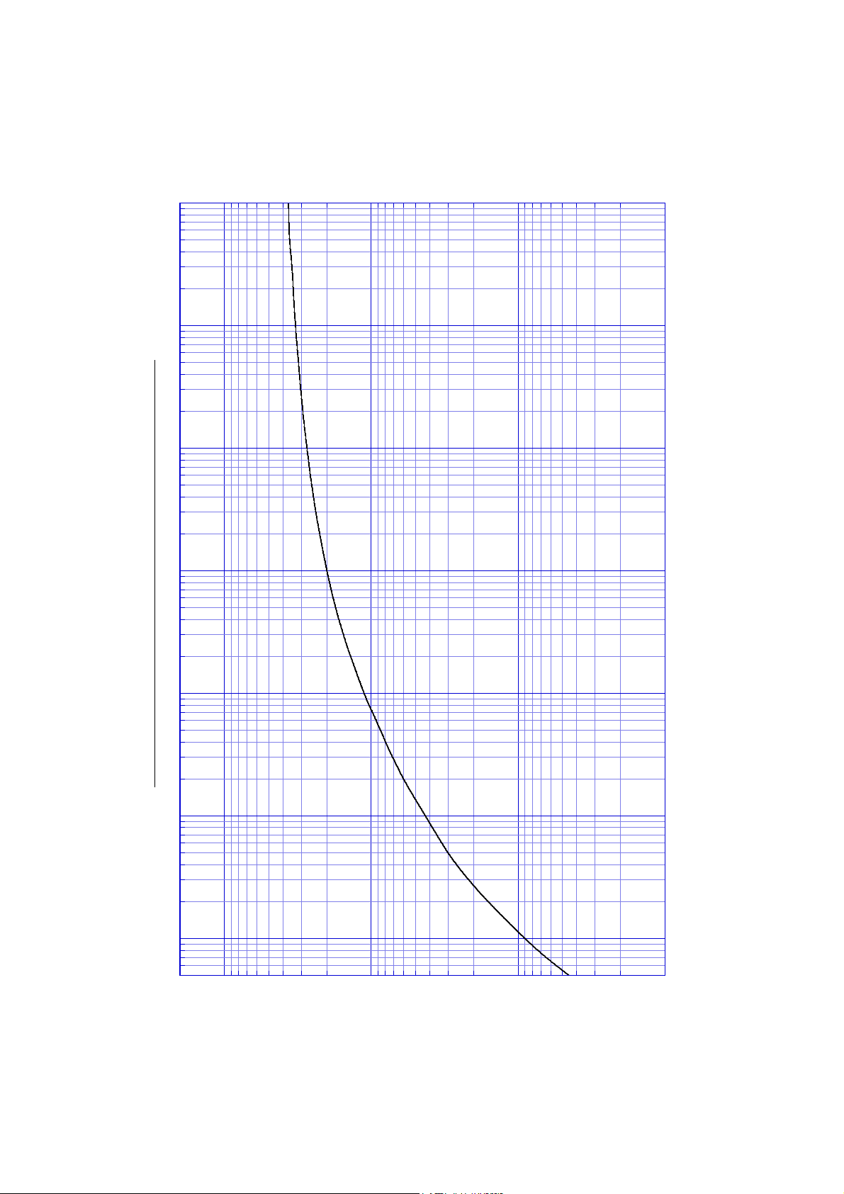
Transient Thermal Impedance
MA3810
10
1
0.1
Time t [s]
-2
10
-3
10
-4
10
0.01
Transient Thermal Impedance θjc(t) [°C/W]
 Loading...