

Shindaiwa LE254, X7502825800 User Manual
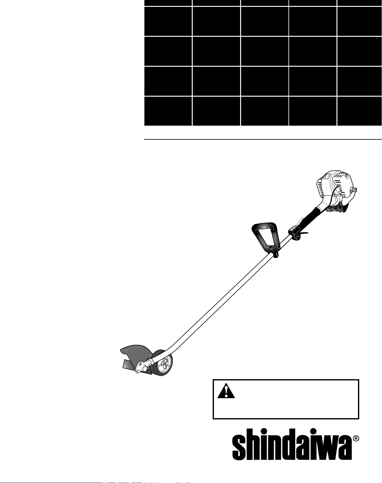
SHINDAIWA OWNER’S/OPERATOR’S MANUAL
LE254
LAWN EDGER
X7502825800
06/10
WARNING!
Always wear eye protection when operating
this machine. To minimize the risk of injury, read this
manual and familiarize yourself with its contents.
Introduction
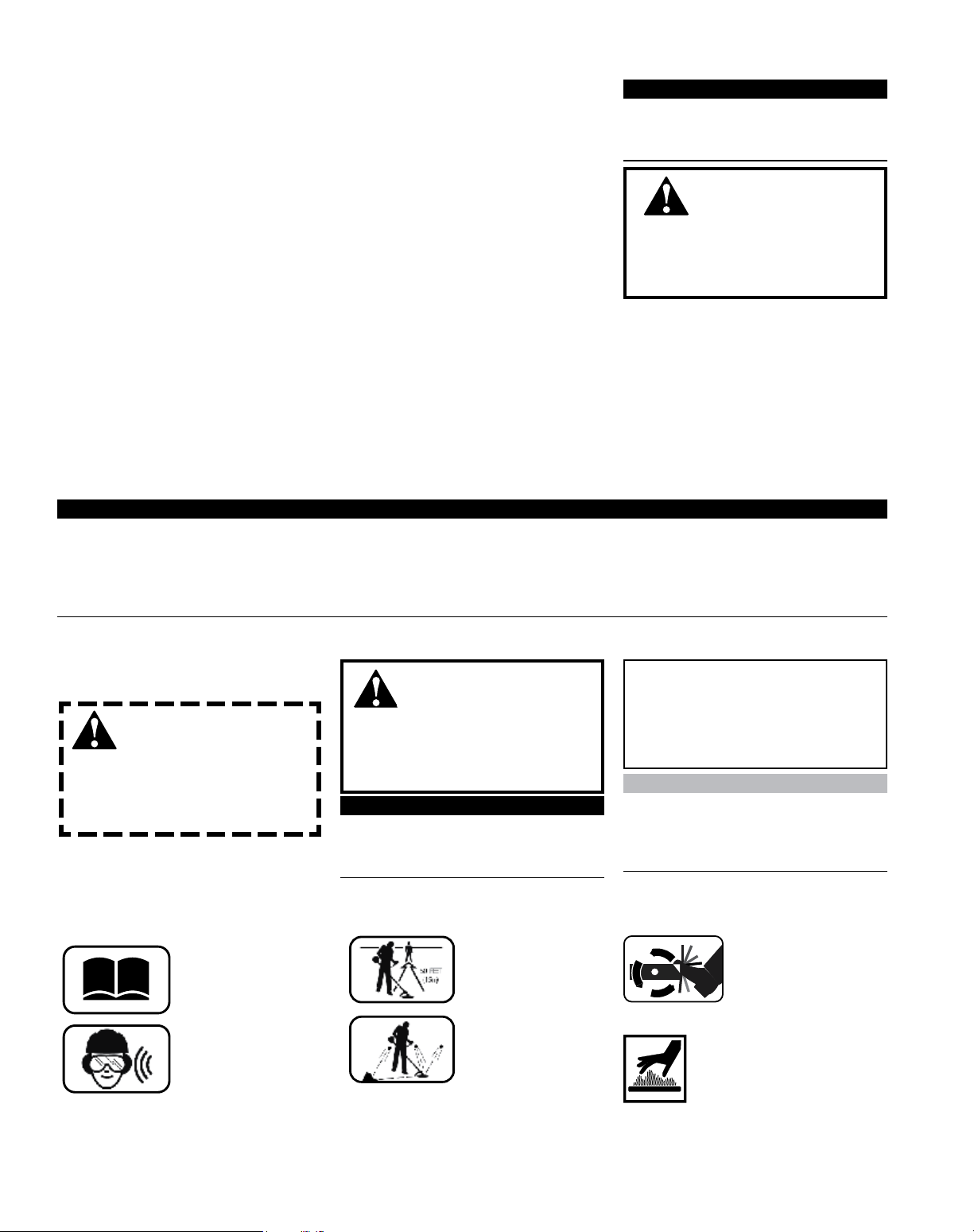
Read and follow this
operators manual.
Failure to do so could
result in serious injury.
Wear eye and hearing
protection at all time
during the operation
of this unit.
Keep bystanders
at least 50 feet (15 m)
away during operation.
Beware of thrown or
ricocheted objects.
HOT SURFACE
The Shindaiwa H4 series has been
designed and built to deliver superior
performance and reliability without compromise to quality, comfort, safety or
durability.
Shindaiwa engines represent the leading edge of high-performance engine
technology, delivering exceptionally high
power with remarkably low displacement and weight. As an owner/operator, you’ll soon discover for yourself why
Shindaiwa is simply in a class by itself!
ECHO, Inc. reserves the right to
make changes to products without
prior notice, and without obligation to
make alterations to units previously
manufactured.
IMPORTANT!
The information contained in these
instructions describes units available at
the time of publication.
WARNING!
The engine exhaust from
this product contains chemicals
known to the State of California to
cause cancer, birth defects or other
reproductive harm.
Contents
Attention Statements .............................2
Safety ....................................................3
Product Description ...............................5
Specications ........................................5
Emission Control ...................................6
PAGE PAGE
Assembly ...............................................6
Mixing fuel .............................................7
Filling the fuel tank.................................8
Starting the Engine ...............................9
Stopping the Engine ............................10
PAGE
Checking Unit Condition ......................10
Operation .............................................11
Maintenance ........................................12
Long Term Storage ..............................18
Troubleshooting Guide ........................19
Warranty Statement ............................22
IMPORTANT!
The operational procedures described in this manual are intended to help you get the most from this unit as well as to protect you and others from harm. These procedures are guidelines for safe operation under most conditions, and are not
intended to replace any safety rules and/or laws that may be in force in your area. If you have questions regarding your
Shindaiwa hand held power equipment, or if you do not understand something in this manual, contact your local Shindaiwa
dealer for assistance. You may also contact Shindaiwa at the address printed on the back of this Manual.
Attention Statements
Throughout this manual are special
“attention statements”.
DANGER!
A statement preceded by
the triangular attention symbol and
the word “DANGER” contains information that should be acted upon
to prevent serious injury or death.
WARNING!
A statement preceded by
the triangular attention symbol and
the word “WARNING” contains information that should be acted upon to
prevent serious bodily injury.
IMPORTANT!
A statement preceded by the word
“IMPORTANT” is one that possesses
special signicance.
CAUTION!
A statement preceded by the word
“CAUTION” contains information
that should be acted upon to prevent mechanical damage.
NOTE:
A statement preceded by the word
“NOTE” contains information that is
handy to know and may make your job
easier.
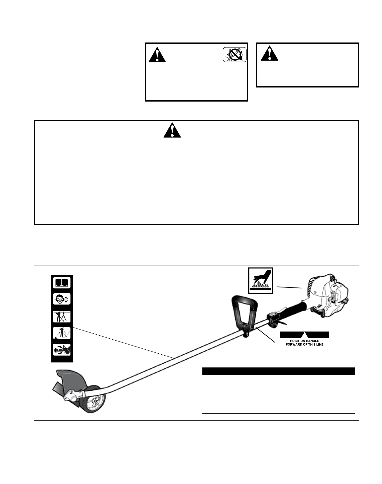
Operational and Warning Labels
2
Keep feet away from
blade. Rotating blade
may cause injury.
Blade may continue to
rotate after the unit is
shut off.
WARNING: Surface can be
hot. Always wear gloves when
handling this unit.
Safety
50 FEET
(15m)
KEEP BYSTANDERS AWAY
AT LEAST 50 FEET (15m)
BEWARE OF THROWN OR
RICHOCHETED OBJECTS
KEEP AWAY FROM
ROTATING BLADE
Shindaiwa
READ THE
OPERATOR’S MANUAL
WEAR HEARING AND
ANSI Z87.1 APPROVED
EYE PROTECTION
P/N 19422-00046
HOT SURFACE
Work Safely
This machine operates at very high
speeds and has the potential to do
serious damage if misused, abused
or mishandled. To reduce the risk
of injury, you must maintain control
at all times, and observe all safety
precautions during operation. Never
permit a person without training or
instruction to operate this machine!
ALWAYS wear eye protection to
shield against thrown objects.
NEVER run the engine when transporting the unit.
NEVER run the engine indoors! Make
sure there is always good ventilation. Fumes from engine exhaust can
cause serious injury or death.
ALWAYS use the proper cutting tool
for the job.
WARNING!
Never operate power
equipment of any kind if you
are tired or if you are under the inuence of alcohol, drugs, medication or
any other substance that could affect
your ability or judgement.
WARNING!
Use Good Judgement
ALWAYS clear your work area of trash
or hidden debris that could be thrown
back at you or toward a bystander.
ALWAYS stop the engine immediately if it suddenly begins to vibrate
or shake. Inspect for broken, missing or improperly installed parts or
attachments.
WARNING!
Never make unauthorized
attachment installations. Do not
use attachments not approved by
Shindaiwa for use on this unit.
Stay Alert
You must be physically and mentally t
to operate this unit safely.
ALWAYS keep the unit as clean as
practical. Keep it free of loose vegetation, mud, etc.
ALWAYS hold the unit rmly with
both hands and maintain control at
all times.
ALWAYS keep the handles clean.
ALWAYS disconnect the spark plug
wire before performing any maintenance work.
Product Description
This label indicates the minimum distance between
front handle and rear grip per ANSI B175.3.
IMPORTANT!
Safety and Operation Information Labels: Make sure all
information labels are undamaged and readable. Immediately replace damaged or missing information labels.
New labels are available. Contact your local authorized
Shindaiwa dealer.
3
Safety (continued)
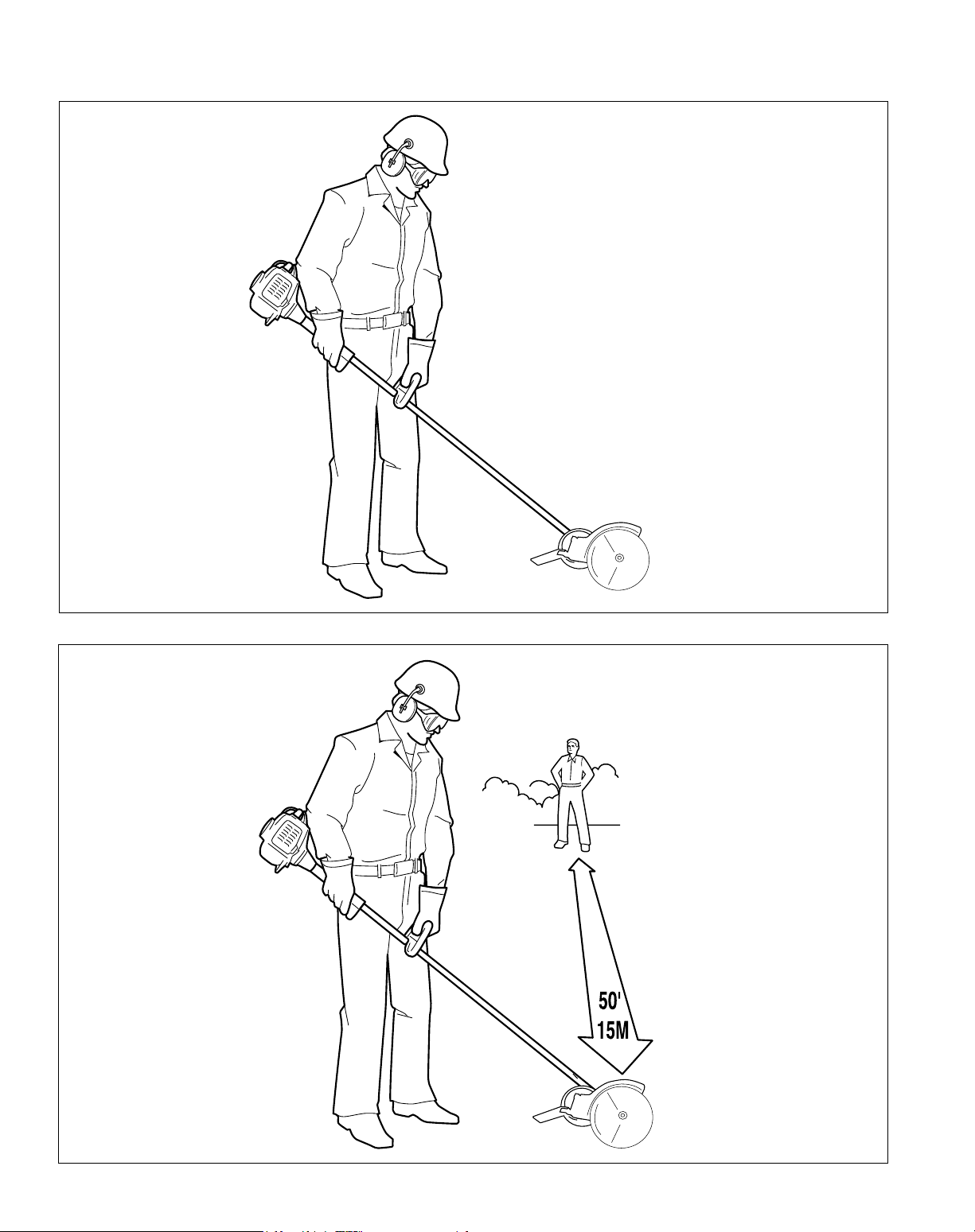
The properly equipped operator
Wear nonslip heavy-duty work
gloves to improve your grip on the
unit’s handle. Wear snug-tting
clothes that also permit freedom of
movement. NEVER wear shorts!
Keep a proper footing and do not
overreach—maintain your balance
at all times during operation.
Wear sturdy footwear with nonslip
soles to provide good footing. Steeltoed safety boots are recommended.
Never operate unit bare-footed!
Always wear eye protection such as goggles or
safety glasses. Wear hearing protection devices
and a broad-brimmed hat or helmet.
Always operate with both hands
rmly gripping the unit.
Keep away from rotating attachments
at all times, and NEVER lift a moving
attachment above waist-height.
Always make sure the appropriate cutting
attachment shield is correctly installed and in
good condition.
Be aware of the working environment
Avoid long-term operation in very
hot or very cold weather.
Be extremely careful of
slippery terrain, especially
during rainy weather.
Be constantly alert for objects and
debris that could be thrown either
from the rotating cutting attachment
or bounced from a hard surface.
When operating in rocky terrain or near
electric wires or fences, use extreme
caution to avoid contacting such items
with the cutting attachment.
Make sure bystanders or observers
outside the 15 meters “danger zone”
wear eye protection.
Reduce the risk of bystanders being
struck by ying debris. Make sure no
one is within 15 meters—that’s about
16 paces—of an operating attachment.
If contact is made with a hard
object, stop the engine and
inspect the cutting attachment
for damage.
Always make sure the
appropriate cutting attachment
shield is correctly installed.
4

Product Description
Using the illustration as a guide,
familiarize yourself with your
machine and its various components.
Understanding your machine helps
ensure top performance, long service
life and safer operation.
Cutting
attachment shield
Shaft tube
Handle
Ignition switch
Throttle Interlock
lever
Grip
Fuel tank
Throttle
Trigger
WARNING!
Do not make unauthorized
modications or alterations to any
of these units or their components.
Edger blade
Gearcase
Specications
Engine Model LE254
Dry weight (Including attachments) 6.3 kg / 14.0 lb.
Engine type 4-cycle, vertical cylinder, air cooled
Bore x stroke 34 x 27 mm / 1.3 x 1.1 in.
Displacement 24.5 cc / 1.5 cu. in.
Fuel/oil ratio 50:1 with *ISO-L-EGD or JASO FD class engine oil
Carburetor type Diaphragm-type
Fuel tank capacity 590 ml / 20.0 oz.
Ignition One-piece electronic, program contolled
Spark plug NGK CMR5H
Electrode Gap
Torque
Air cleaner type Foam pre-lter; sealed felt main lter
Starting method Recoil
Stopping method Slide switch
Transmission type Automatic, centrifugal clutch w/bevel gear
Edger Blade 7.75 inch/197 mm Steel Edger Blade
Idle Speed (RPM) 3,000 RPM
Clutch Engagement Speed (RPM) 4,100 RPM
Wide Open Throttle (RPM) 10,500 RPM
0.6 mm / 0.024 in.
16.7 - 18.6 N∙m (148-165 in • lbf)
Specications are subject to change without notice.
IMPORTANT!
This spark ignition system complies with the Canadian standard ICES-002.
5
Emission Control (exhaust & evaporative)
EPA 2010 and Later and/or C.A.R.B. TIER III
The emission control system for the engine is EM/TWC (Engine Modication and 3-way Catalyst) and for the fuel tank the
Control System is EVAP (Evaporative Emissions) or N (for nylon tank). Evaporative emission may be applicable to California
models only.
Emission Control Label (located on Engine) (EXAMPLE ONLY, information on label varies by FAMILY).
PRODUCT EMISSION DURABILITY (EMISSION COMPLIANCE PERIOD)
The 300 hour emission compliance period is the time span selected by the manufacturer certifying the engine emissions
output meets applicable emissions regulations, provided that approved maintenance procedures are followed as listed in
the Maintenance Section of this manual.
Assembly
Prior to assembly
Before assembling, make sure you have
all the components required for a complete unit. Carefully inspect all components for damage.
Outer Tube/Main Shaft Assembly ■
■
Cutting Attachment Shield
Edger Blade ■
Kit containing this owner's/opera- ■
tor's manual, and a tool kit for routine maintenance.
The terms “left”, “left-hand”, and
“LH”; “right”, “right-hand”, and “RH”;
“front” and “rear” refer to directions as
viewed by the operator during normal
operation.
IMPORTANT!
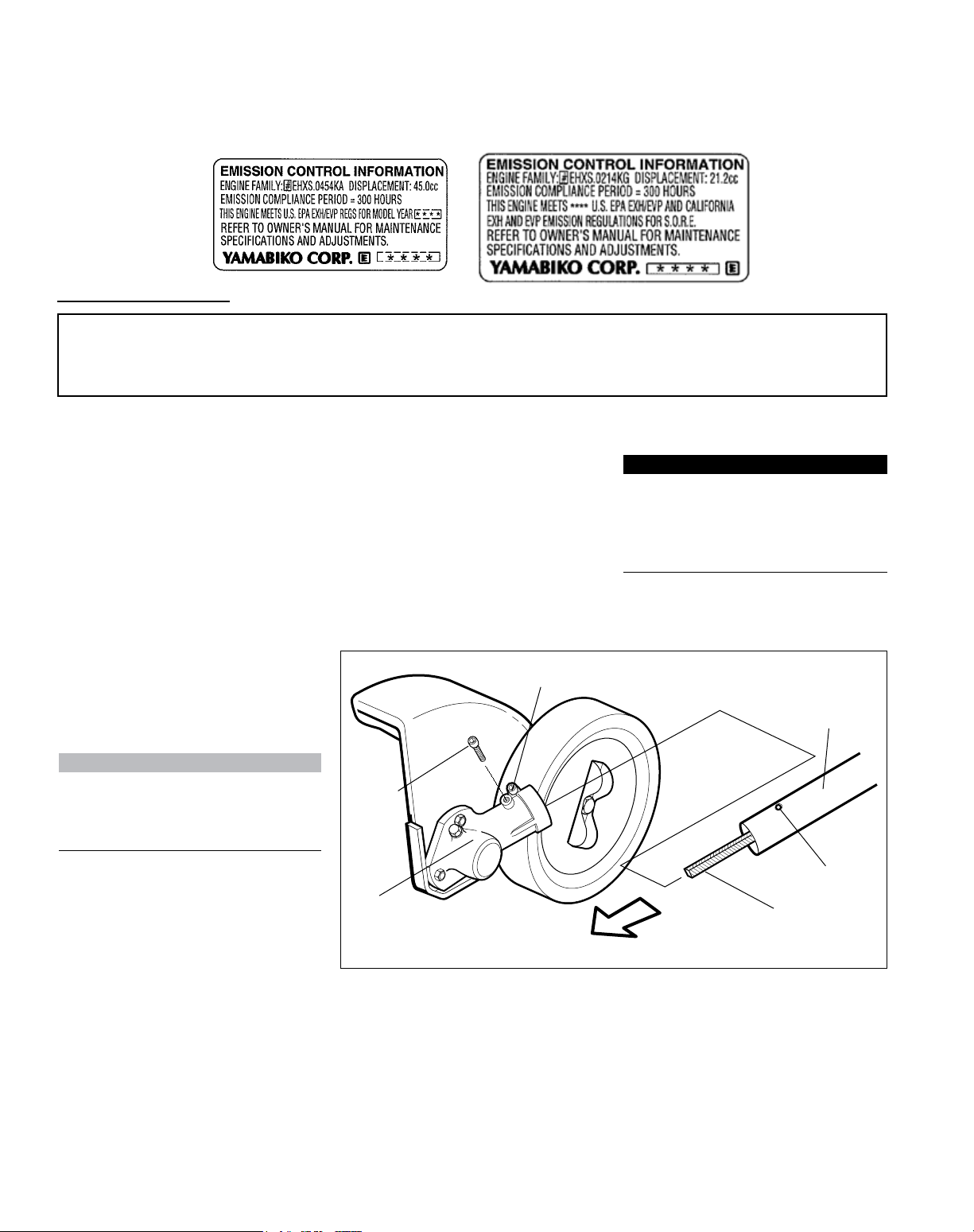
Mounting the cutting attachment shield and edger blade
Loosen gearcase clamp screw.1.
Remove the gearcase index screw.2.
Gearcase
clamp screw
Slide gearcase on to shaft tube, 3.
engaging ex drive cable with
female socket in gearcase.
NOTE:
It may be necessary to pull the ex
cable out from the shaft tube, engage
Gearcase
index
screw
into the gearcase and then slide the
assembly onto the shaft tube.
Align index screw hole in gearcase 4.
with index hole in shaft tube,
and install index screw. Tighten
Gearcase
securely.
Tighten the clamp bolt and torque 5.
to 5.9 - 8.0 N•m (52 - 69 in•lbs).
Shaft tube
Index hole
Flex drive cable
6
Assembly (continued)
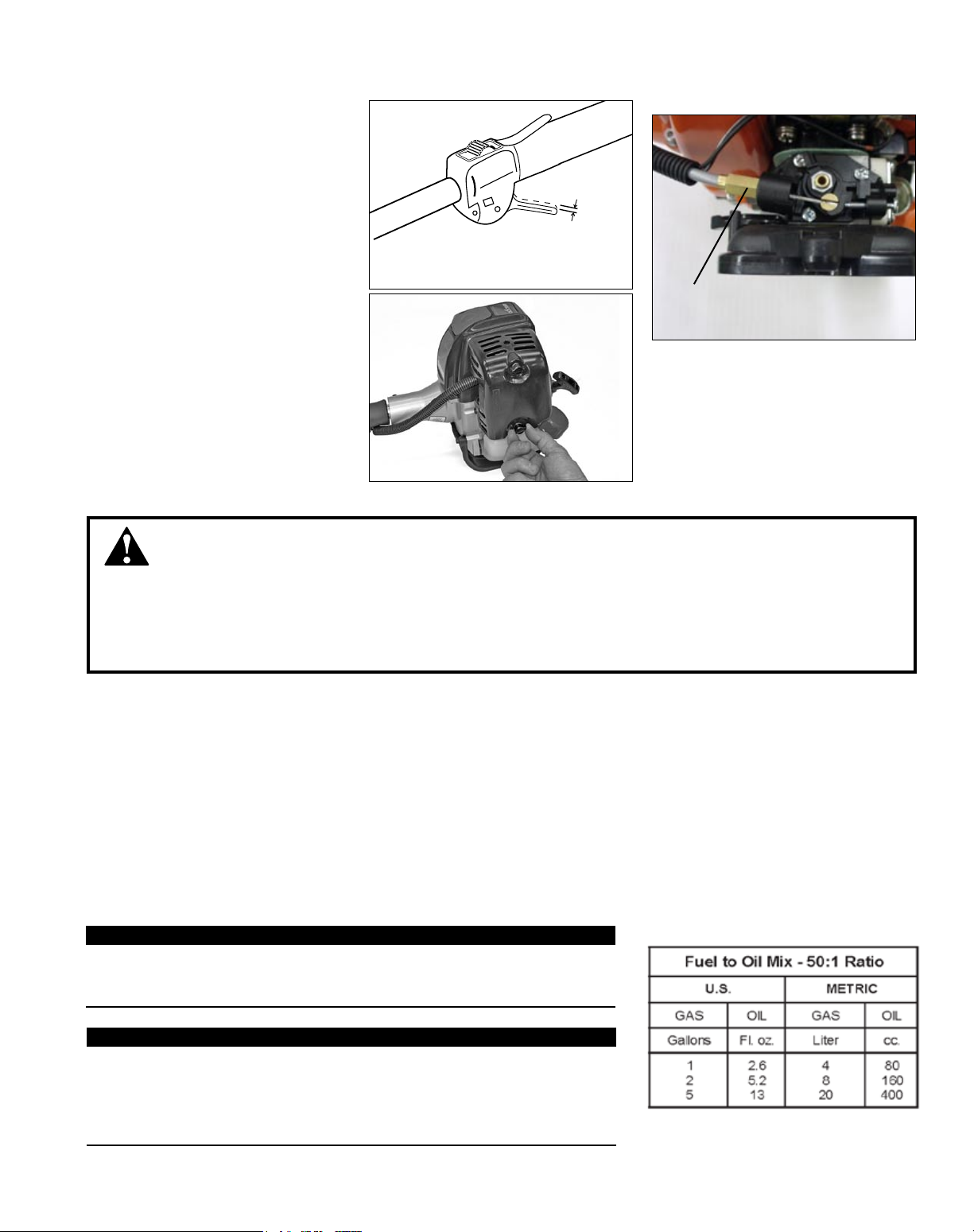
Adjust Throttle Trigger Free Play
The throttle trigger free play should be
approximately 4 - 6 mm (3/16” - 1/4”).
Make sure that the throttle lever operates smoothly without binding. If it
becomes necessary to adjust the lever
free play, follow the procedures and
illustrations that follow.
Loosen the air cleaner cover knob 1.
and remove the air cleaner cover.
Turn the cable adjuster in or out as 2.
required to obtain proper free play
4-6 mm.
Reinstall the air cleaner cover.3.
Mixing Fuel
Throttle Trigger
Free Play
Remove air
cleaner cover
4-6 mm
(3/16”-1/4”)
Cable
Adjuster
Adjust as required for
4-6 mm free play
WARNING!
Alternative fuels, such as E15 (15% ethanol), E-85 (85% ethanol) or any fuels not meeting Shindaiwa requirements are NOT approved for use in Shindaiwa gasoline engines. Use of alternative fuels may cause performance
problems, loss of power, overheating, fuel vapor lock, and unintended machine operation, including, but not limited to,
improper clutch engagement. Alternative fuels may also cause premature deterioration of fuel lines, gaskets, carburetors and other engine components.
Fuel Requirements
Gasoline - Use 89 Octane [R+M/2] (mid grade or higher) gasoline known to be good quality. Gasoline may contain up to
10% Ethanol (grain alcohol) or 15% MTBE (methyl tertiary-butyl ether). Gasoline containing methanol (wood alcohol) is
NOT approved.
Hybrid 4TM Mixture Oil - Engine oil meeting ISO-L-EGD (ISO/CD 13738) and J.A.S.O. M345/FD standards must be
used. Shindaiwa highly recommends using Shindaiwa Red ArmorTM engine oil in all Shindaiwa Hybrid 4TM engines to
protect the engine from harmful carbon build up, maintain engine performance, and increase engine life. Shindaiwa
Red ArmorTM engine oil exceeds ISO-L-EGD and J.A.S.O. M345/FD performance requirements. Engine problems
due to inadequate lubrication caused by failure to use an ISO-L-EGD (ISO/CD 13738) and J.A.S.O. M345/FD certi-
ed oil will void the engine warranty.
IMPORTANT!
Shindaiwa Red Armor
TM
engine oil may be mixed at 50:1 ratio for application
in all Shindaiwa engines sold in the past, regardless of ratio specied in those
manuals.
Examples of 50:1 mixing quantities
IMPORTANT!
Stored fuel ages. Do not mix more fuel than you expect to use in thirty (30)
days, ninety (90) days when a fuel stabilizer is added. Use of unmixed, improp-
erly mixed, or stale fuel, may cause hard starting, poor performance, or severe
engine damage and void the product warranty. Read and follow instructions in
the Long Term Storage section of this manual.
7

Handling Fuel
DANGER
Fuel is VERY ammable. Use extreme care when mixing, storing or handling or serious personal injury
may result.
• Use an approved fuel container.
• DO NOT smoke near fuel.
• DO NOT allow ames or sparks near fuel.
• Fuel tanks/cans may be under pressure. Always loosen fuel caps slowly allowing pressure to equalize.
• NEVER refuel a unit when the engine is HOT or RUNNING!
• DO NOT ll fuel tanks indoors. ALWAYS ll fuel tanks outdoors over bare ground.
• DO NOT overll fuel tank. Wipe up spills immediately.
• Securely tighten fuel tank cap and close fuel container after refueling.
• Inspect for fuel leakage. If fuel leakage is found, do not start or operate unit until leakage is repaired.
• Move at least 3m (10 ft.) from refueling location before starting the engine.
Mixing Instructions
1. Fill an approved fuel container with half of the required
amount of gasoline.
2. Add the proper amount of engine oil to gasoline.
3. Close container and shake to mix oil with gasoline.
4. Add remaining gasoline, close fuel container, and remix.
IMPORTANT!
Spilled fuel is a leading cause of hydrocarbon emissions.
Some states may require the use of automatic fuel shutoff containers to reduce fuel spillage.
After use
• DO NOT store a unit with fuel in its tank. Leaks can occur.
Return unused fuel to an approved fuel storage container.
Storage - Fuel storage laws vary by locality. Contact your
local government for the laws affecting your area. As a precaution, store fuel in an approved, airtight container. Store
in a well-ventilated, unoccupied building, away from sparks
and ames.
IMPORTANT!
Stored fuel may separate. ALWAYS shake fuel container
thoroughly before each use.
Filling the fuel tank
CAUTION!
Slowly remove the fuel cap only after stopping the engine
WARNING!
Minimize the Risk of Fire
NEVER ■ smoke or light res near the engine.
■ stop the engine and allow it to cool before
ALWAYS
refueling.
■ Wipe all spilled fuel and move at least 3
ALWAYS
meters (10 feet) from the fueling point and source before
starting.
■ place ammable material close to the engine
NEVER
mufer.
NEVER ■ operate the engine without the mufer and spark
arrester screen in place and in good working condition.
FUEL IS HIGHLY FLAMMABLE. ■
Place the unit on a at, level surface.1.
Clear any dirt or other debris from around the fuel ller cap.2.
ALWAYS ■ store gasoline in a container approved for
ammable liquids.
■ inspect the unit for fuel leaks before each
ALWAYS
use. During each rell, check that no fuel leaks from
around the fuel cap and/or fuel tank.
If fuel leaks are evident, stop using the unit immediately. Fuel leaks must be repaired before using the unit.
ALWAYS ■ move the unit at least 3 meters (10 feet)
away from a fuel storage area or other readily am-
mable materials before starting
the engine.
Remove the fuel cap, and ll the tank with clean, fresh 3.
fuel.
Reinstall the fuel ller cap and tighten rmly.4.
Wipe away any spilled fuel before starting engine.5.
8
After engine starts,
move choke to OPEN position
Set the choke lever to the CLOSED position
Starting the Engine
WARNING!
The attachment will operate immediately when the engine starts, and could result in possible serious injury.
Keep movable parts of the attachment away from objects that could become entangled or thrown, and surfaces that
could cause loss of control.
IMPORTANT!
Engine ignition is controlled by a two position switch mounted on the throttle housing labeled, “I” for ON or START and “O” for OFF
or STOP.
Slide the ignition switch to the “ON” 1.
position.
Set the throttle trigger to the “fast 2.
idle”:
Depress and hold the throttle a.
interlock, then squeeze the throttle trigger.
Depress and hold the fast idle b.
button.
Release the throttle trigger and c.
throttle interlock, then release fast
idle button.
Press the primer bulb until fuel 3.
can be seen owing in the transparent return tube.
IMPORTANT!
The primer system only pushes fuel
through the carburetor. Repeatedly
pressing the primer bulb will not ood
the engine with fuel.
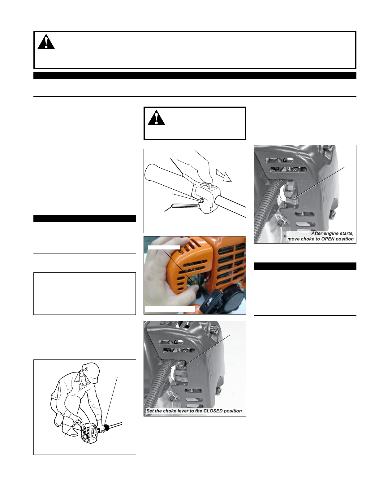
Set the choke lever to the CLOSED 4.
position if engine is cold.
CAUTION!
Do not pull the recoil starter to the
end of the rope travel. Pulling the
recoil starter to the end of the rope
travel can damage the starter.
While holding the outer tube rmly-5.
with left hand. Use your other hand
to slowly pull the recoil starter handle until resistance is felt, then pull
quickly to start the engine.
Hold
the unit
rmly...
WARNING!
Never start the engine from
the operating position.
Throttle Interlock
Fast Idle
Button
Throttle Trigger
Slide ignition to ON
Primer Bulb
Press primer bulb...
ON
Close
choke
When the engine starts, slowly 6.
move the choke lever to the “OPEN”
position. (If the engine stops after
the initial start, close the choke and
restart.)
Open
Operating the throttle will automati-7.
cally disengage the fast idle setting.
IMPORTANT!
If the engine fails to start after several
attempts with the choke in the closed
position, the engine may be ooded
with fuel. If ooding is suspected, refer
to the ”Starting a Flooded Engine”
section of this manual.
When the Engine Starts...
After the engine starts, allow the
■
engine to warm up at idle 2 or 3
minutes before operating the unit.
Advancing the throttle makes the cut- ■
ting attachment move faster; releasing
the throttle permits the attachment to
stop moving. If the cutting attachment
continues to move when the engine
returns to idle, carburetor idle speed
should be adjusted. (See “Adjusting
Engine Idle”.)
...and pull recoil
starter handle
upward
Make sure the
attachment is clear
of obstructions!
9
 Loading...