

Shindaiwa 80558, T260, T261 Instructions Manual

SHINDAIWA GRASS TRIMMER TO BLADE CONVERSION
INSTRUCTIONS
WARNING!
Minimize the risk of injury to yourself and others! Read the Owner's/Operator's manual originally supplied with the unit that is being upgraded and
familiarize yourself with the contents. Always wear eye and hearing protection when operating your unit.
X7502235801
08/10
Model 80558 For Trimmer T260, T261
2
CAUTION!
A statement preceded by the word “CAUTION” contains
information that should be acted upon to prevent mechanical
damage.
IMPORTANT!
A statement preceded by the word “IMPORTANT” is one that
possesses special signicance.
NOTE:
A statement preceded by the word “NOTE” contains information
that is handy to know and may make your job easier.
Throughout this manual are special “attention statements”.
WARNING!
A statement preceded by the triangular attention symbol and the word “WARNING” contains information that should be
acted upon to prevent serious bodily injury.
Attention Statements
Introduction
PAGE
These are instructions to convert a grass trimmer to a blade capable unit. This is not an Owner's/Operator's manual. Information on how to operate and maintain the unit can be found in the Owner's/Operator's manual for the unit you are converting. Note this kit is supplied with a cutting attachment shield that has been redesigned to provide better visibility and a
larger cutting swath when used as a grass trimmer.
Attention Statements ........................2
Safety Labels ....................................3
Contents
IMPORTANT!
The instructions described in this manual are intended to help
you get the most from your Shindaiwa power tool as well as
to protect you and others from harm. These procedures are
guidelines for safe operation under most conditions, and are
not intended to replace any safety rules and/or laws that may
be in force in your area. If you have questions regarding your
Shindaiwa power tool, or if you do not understand something in
these instructions, your Shindaiwa dealer will be glad to assist
you. You may also contact Shindaiwa at the address printed on
the back of this instructional manual.
General Safety Instructions ..............3
Kit Contents ......................................3
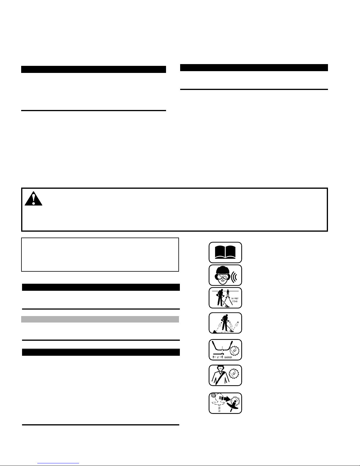
Read and follow this
operators manual.
Failure to do so could
result in serious injury.
Wear eye and hearing
protection at all times
during the operation
of this unit.
Keep bystanders
at least 50 feet (15 m)
away during operation.
Beware of thrown or
ricocheted objects.
Do not operate this unit
with a blade unless the
unit is equipped with a
Shindaiwa-approved
handlebar or barrier.
Always wear a harness
when operating this unit
with a blade. A harness
is also recommended when
using trimmer line.
If unit is used as a
brushcutter, beware of
blade thrust. A jammed
blade can cause the unit
to jerk suddenly and may
cause the operator to
lose control of the unit.
Assembly ..........................................4
Shoulder Strap..................................8
Using a Brushcutter Blade ................8
PAGE PAGE
IMPORTANT!
The information contained in these instructions describes
the product available at the time of publication.
Echo, Inc. reserves the right to make changes to products
without prior notice, and without obligation to make alterations to units previously manufactured.
IMPORTANT!
If the cutting attachment shield has been removed from
your unit or the unit was manufactured prior to October
2001, an additional clamp kit will be required to complete
this installation. The clamp kit required is Shindaiwa part
number 80292.
3
Safety and Operation Information Labels: Make sure
all information labels are undamaged and readable.
Immediately replace damaged or missing information
labels. A new label is provided in this kit and additional
labels are available from your local authorized Shindaiwa dealer. Prior to installing the new label, Remove
old label and clean the outer tube with rubbing alcohol
or similar cleaner.
IMPORTANT!
Safety Labels
When operating with a blade, make sure the handle ■
is positioned to provide you with maximum protection from contacting the blade. Always make sure the
handlebar is installed in accordance with the manufacturers instruction.
NEVER
■ use a cracked or warped blade: If a properly
installed blade vibrates, replace it with a new one and
re-check.
WARNING!
ALWAYS
■ Shut off the engine immediately if a blade
binds in a cut. Push the branch or tree to ease the
bind and free the blade.
Beware of a coasting blade when brushcutting or
■
edging. A coasting blade can injure while it continues to spin after the throttle trigger is released or
after the engine is stopped.
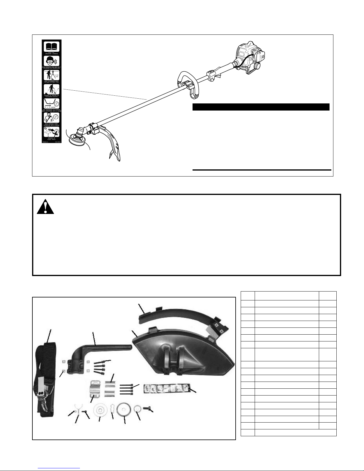
Kit Contents
General Safety Instructions
3
4
5
6
7
8
9
10
11
12
13
14
15
16
17
# Description Qty
1 Warning Label 1
2 Debris Shield 1
3 Debris Shield Extension 1
4 Upper Clamp 1
5 Spacer 2
6 Shoulder Strap 1
7 Hanger 1
8
M5 x 12 mm Socket
Head Cap Screw
1
9 M5 Nut 1
10 M5 x 35 mm SPW Bolt 4
11 Barrier Bar 1
12 M5 Nut 4
13 Bolt Guard 1
14 8 x 20 mm SW Bolt 1
15 Holder (A) 1
16 Holder (B) 1
17 Safety Clip 1
18 M5 x 45 mm SPW Bolt 4
19 Assembly Tool (s)
BCC03
18
1
2
4
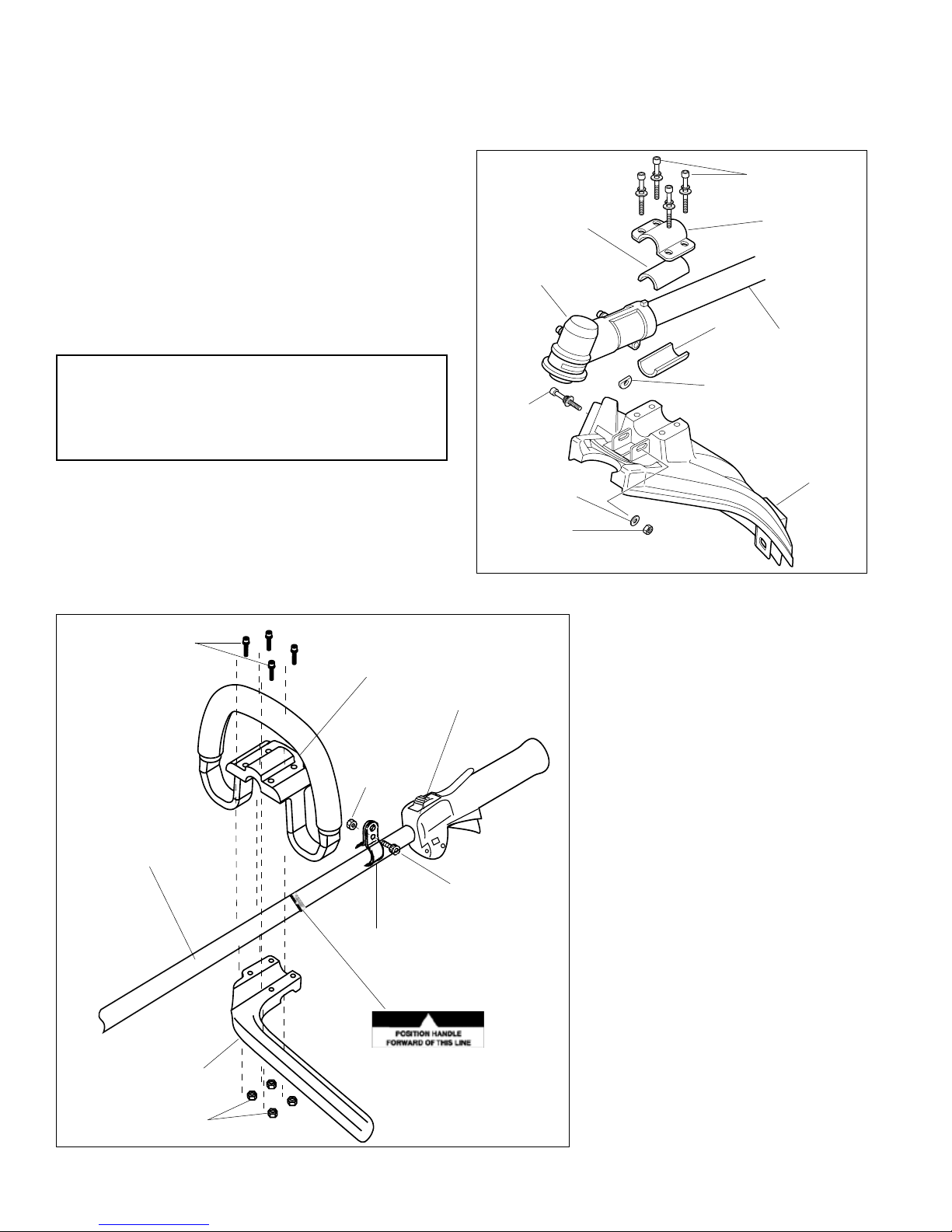
Barrier Bar and Hanger Assembly
Assembly
Removing the Old Cutting Attachment Shield
Remove the Existing Cutting Attachment Shield.
TSU05
Cutting
Attachment
Shield
Washer
Retaining
Nut
Gearcase
Clamp
Screw
D-washer
Shim
Gearcase
Housing
Shim Bracket
Socket-Head Cap
Screws
Outer Tube
Figure 1
1. Remove the four socket-head cap screws, bracket and
two shims. See Figure 1.
2. Remove the retaining nut, washer and gearcase clamp
screw. If possible, do not disturb the D-washer.
3. Remove the cutting attachment shield from the
gearcase.
CAUTION!
The D-Washer is a spacer that prevents overtightening
and must remain in place to prevent possible damage to
the gearcase clamp.
BCC07
1. Remove the four socket-head cap
screws on the handle and remove the
handle and mounting bracket.
2. Unscrew gearcase housing locating
screw, and slide gearcase off of outer
tube.
3. Position the hanger on the outer tube
between the handle and throttle assembly and secure the hanger with the nut
and bolt as shown in Figure 2.
4. Slide gear case on to outer tube and
align locating holes.
5. Thread locating screw into locating
hole, and tighten securely.
6. Position the handle on the outer tube
forward of Handle Positioning Label as
shown in Figure 2.
7. Install the barrier bar with the sockethead cap screws and nuts. Tighten the
screws nger-tight ONLY at this time.
8. Locate the handle in the best position
for operator comfort (usually about 10
inches ahead of the throttle housing).
9. Secure the handle by alternately tightening the four socket-head screws in a
diagonal or “criss-cross” fashion.
Outer Tube
Socket-head
Capscrews
Handle
Barrier Bar
Throttle Assembly
Figure 2
Handle Positioning Label
Bolt
Nut
Hanger
Nuts
 Loading...