

Shindaiwa T2500, T2500X Owner's/operator's Manual
SHINDAIWA OWNER’S/
OPERATOR’S MANUAL
T2500 TRIMMER
T2500X TRIMMER
WARNING!
Minimize the risk of injury to yourself and others! Read this
manual and familiarize yourself with the contents. Always
wear eye and hearing protection when operating this unit.
Part Number 80546
Rev. 8/02
T2500
T2500X
MANUAL DEL PROPIETARIO/
OPERADOR SHINDAIWA
PODADORA T2500
PODADORA T2500X
¡Advertencia!
Disminuya el riesgo de sufrir lesiones o causar lesiones a otros!
Lea este manual y familiaricese con su contenido. Siempre use
protección para los ojos y oídos cuando opere esta máquina.
Part Number 80546
Rev. 8/02
T2500
T2500X
Throughout this manual are special
“attention statements”.
IMPORTANT!
The operational procedures described
in this manual are intended to help you
get the most from this unit as well as to
protect you and others from harm.
These procedures are guidelines for
safe operation under most conditions,
and are not intended to replace any
safety rules and/or laws that may be in
force in your area. If you have questions
regarding your 2500 series hand held
power equipment, or if you do not
understand something in this manual,
your Shindaiwa dealer will be glad to
assist you. You may also contact
Shindaiwa, Inc. at the address printed
on the back of this Manual.
Attention Statements
Introduction
PAGE
The Shindaiwa 2500 Series hand held
power equipment has been designed
and built to deliver superior performance and reliability without compromise to quality, comfort, safety or
durability.
Shindaiwa engines represent the
leading edge of high-performance
engine technology, delivering exceptionally high power with remarkably low
displacement and weight. As an owner/
operator, you’ll soon discover for
yourself why Shindaiwa is simply in a
class by itself!
Shindaiwa Inc. reserves the right to
make changes to products without
prior notice, and without obligation to
make alterations to units previously
manufactured.
Attention Statements........................... 2
Safety Information ............................... 2
Safety Labels ........................................ 4
Product Description ............................ 5
Specifications ....................................... 5
Assembly and Adjustments ................ 6
Engine Fuel .......................................... 9
Starting the Engine ............................. 9
Stopping the Engine.......................... 10
Adjusting Engine Idle ....................... 10
Checking Unit Condition.................. 11
Shoulder Strap ................................... 11
Cutting Grass with a Trimmer Head .. 11
Using a Blade (T2500X) ..................... 12
Maintenance ...................................... 13
Long Term Storage ........................... 16
Troubleshooting Guide .................... 17
Emission System Warranty...............19
Contents
IMPORTANT!
The information contained in this
owner's/operator's manual describes
units available at the time of publication.
CAUTION!
A statement preceded by the word
“CAUTION” contains information
that should be acted upon to prevent
mechanical damage.
WARNING!
A statement preceded by the
triangular attention symbol and the
word “WARNING” contains information that should be acted upon to
prevent serious bodily injury.
Work Safely
Shindaiwa trimmers operate at very
high speeds and can do serious damage
or injury if they are misused or abused.
Never allow a person without training or
instruction to operate this unit!
Stay Alert
You must be physically and mentally fit
to operate this unit safely.
General Safety Instructions
WARNING!
WARNING!
Never operate power equipment of
any kind if you are tired or if you are
under the influence of alcohol,
drugs, medication or any other
substance that could affect your
ability or judgement.
WARNING!
Minimize the Risk of Fire
NEVER smoke or light fires near
the engine.
ALWAYS stop the engine and allow
it to cool before refueling. Avoid
overfilling and wipe off any fuel that
may have spilled.
ALWAYS inspect the unit for fuel
leaks before each use. During each
refill, check that no fuel leaks from
around the fuel cap and/or fuel
tank. If fuel leaks are evident, stop
using the unit immediately. Fuel
leaks must be repaired before
using the unit.
ALWAYS move the unit to a place
well away from a fuel storage area
or other readily flammable materials
before starting the engine.
NEVER place flammable material
close to the engine muffler.
NEVER operate the engine without
the spark arrester screen in place.
Never make unauthorized
attachment installations. Do not use
attachments not approved by
Shindaiwa for use on this unit.
WARNING!
The engine exhaust from this
product contains chemicals known
to the State of California to cause
cancer, birth defects or other
reproductive harm.
NOTE:
A statement preceded by the word
“NOTE” contains information that is
handy to know and may make your
job easier.
IMPORTANT!
A statement preceded by the word
“IMPORTANT” is one that possesses
special significance.
Read and follow this
operators manual.
Failure to do so could
result in serious injury.
Wear eye and hearing
protection at all times
during the operation
of this unit.
Keep bystanders
at least 50 feet (15 m)
away during operation.
Beware of thrown or
ricocheted objects.
Do not operate this unit with a
blade unless the unit is equipped
with a Shindaiwa-approved
handlebar or barrier.
Always wear a harness when
operating this unit with a blade.
A harness is also recommended
when using trimmer line.
If unit is used as a brushcutter,
beware of blade thrust. A jammed
blade can cause the unit to jerk
suddenly and may cause the
operator to lose control of the unit.
2
A travéz de este manual se encuentran
“declaraciones de seguridad” especiales.
IMPORTANTE!
El propósito de los procedimientos
operacionales descritos en este manual
es ayudarle a obtener el más alto
rendimiento de su máquina y proteger a
usted y a otras personas de sufrir
lesiones. Estos procedimientos son
pautas operativas para una operación
segura bajo la mayoría de condiciones y
no tienen el propósito de substituir las
normas y/o leyes vigentes en su área.
Si tiene alguna pregunta relacionada
con su Serie 2500 o si no entiende
alguna información contenida en este
manual, consulte a su distribuidor
Shindaiwa, quien le atenderá con gusto.
También puede comunicarse con
Shindaiwa Inc. a la dirección que
aparece en la contra portada de
este manual.
Declaraciones De
Seguridad
Introducción
Página
La desmalezadora Shindaiwa Serie
2500 ha sido diseñada y construida para
suministrar un rendimiento superior
sin comprometer calidad, comodidad
ni durabilidad.
Los motores Shindaiwa representan
la tecnología líder de motores de alto
rendimiento, de poco peso y pequeña
cilindrada con excepcional alta potencia.
Como propietario/operario, usted no
tardara en comprobar que Shindaiwa es
la única maquina en esta clase!
CONTENIDO
IMPORTANTE!
La información contenida en este
manual describe unidades disponibles a
la fecha de su publicación.
Precaución!
Toda información precedida por la
palabra PRECAUCION! contiene
información que se debe cumplir
para evitar daños mecánicos.
¡Advertencia!
Toda información precedida por un
símbolo triangular de advertencia y
la palabra ADVERTENCIA! contiene
información o procedimientos que se
deben cumplir para evitar lesiones.
Trabaje con cuidado
Podadoras Shindaiwa operan a
velocidades altas y pueden causar daños
o lesiones serias si son mal usadas o
abusadas. Nunca permita que una
persona sin entrenamiento o instrucción
opere esta unidad!
Mantengase Alerta
Usted debe estar en optimas
condiciones física y mental para operar
esta maquina en forma segura.
Instrucciones Generales
de Seguridad
¡Advertencia!
Nunca instale accesorios no
autorizados. No use accesorios
no aprobados por Shindaiwa en
esta unidad.
¡Advertencia!
Las emisiones emitidas por el tubo
de escape de este producto
contienen substancias químicas que
en el estado de California son
consideradas como causantes de
cáncer, defectos congénitos u
otros efectos nocivos a la
reproducción humana.
NOTA:
Toda información precedida por la
palabra “NOTA” contiene información
útil que puede hacer su trabajo más fácil.
IMPORTANTE!
Toda información precedida por la
palabra “IMPORTANTE” contiene
información especial y significante.
Shindaiwa Inc. se reserva el derecho
de realizar cambios a sus productos
sin previo aviso, y sin la obligación de
hacer modificaciones a máquinas
fabricadas previamente.
Declaraciones de seguridad ...............2
Información de seguridad .................. 2
Etiquetas de seguridad ....................... 4
Descripción del producto .................. 5
Especificaciones .................................. 5
Ensamblaje y Ajustes .......................... 6
Combustible ......................................... 9
Arranque del motor ............................ 9
Parada del motor ............................... 10
Ajuste de marcha mínima................. 10
Verificación de la condición
de la unidad ........................................ 11
Correa de arnés ................................. 11
Corte de césped con cabezal ........... 11
Usando un disco (T2500X)............... 12
Mantenimiento .................................. 13
Almacenamiento de largo plazo ...... 16
Guia diagnóstico ................................ 17
Garantía del sistema de emisiones.. 19
¡Advertencia!
Nunca opere ninguna máquinaria
motorizada si está cansado o si
está bajo la influencia de alcohol,
drogas o medicamentos o cualquier
otra substancia que pueda afectar
su abilidad y juicio.
¡Advertencia!
Disminuya El Riesgo de
Incendios
NUNCA fume ni encienda fuegos
cerca del motor.
SIEMPRE pare el motor y permita
que se enfrie antes de volver a
llenar el tanque. Evite sobre llenar
el tanque y limpie cualquier
derrame de combustible.
SIEMPRE: Inspeccione la máquina
por pérdidas de combustible, antes
de cada uso. Durante cada llenado,
verifique posibles pérdidas
alrededor de la tapa o tanque de
combustible. Si existen pérdidas de
combustible evidentes, pare
inmediatamente el motor. Pérdidas
de combustible deben de ser
reparadas antes de cada uso.
SIEMPRE aleje la máquina del área
de combustible o de otros
materiales inflamables antes de
arrancar el motor.
NUNCA coloque materiales
inflamables cerca del silenciador de
la máquina.
NUNCA opere el motor sin la malla
del guardachispas en su lugar.
2
Lea y siga las recomendaciones de
este manual del operario. De no hacerlo
podría resultar en lesiones graves.
Use protección para los ojos y protección
para los oídos en todo momento que este
operando esta maquina.
Mantenga a los transeúntes a una
distancia mínima de 15 metros (50 pies)
mientras la maquina este en operación.
Mantengase alerta por objetos lanzados
o rebotes.
No opere esta unidad con un disco/
cuchilla al menos que este equipada con
un mango aprobado por Shindaiwa.
Siempre use un arnés cuando opere esta
unidad con disco/cuchilla. Un arnés
también es recomendado cuando use
cable de nylon.
Si esta unidad se usa como una
desmalezadora, mantengase alerta por
los rebotes del disco. Un disco atascado
puede causar movimientos repentinos y
puede que el operador pierda control de
la maquina.
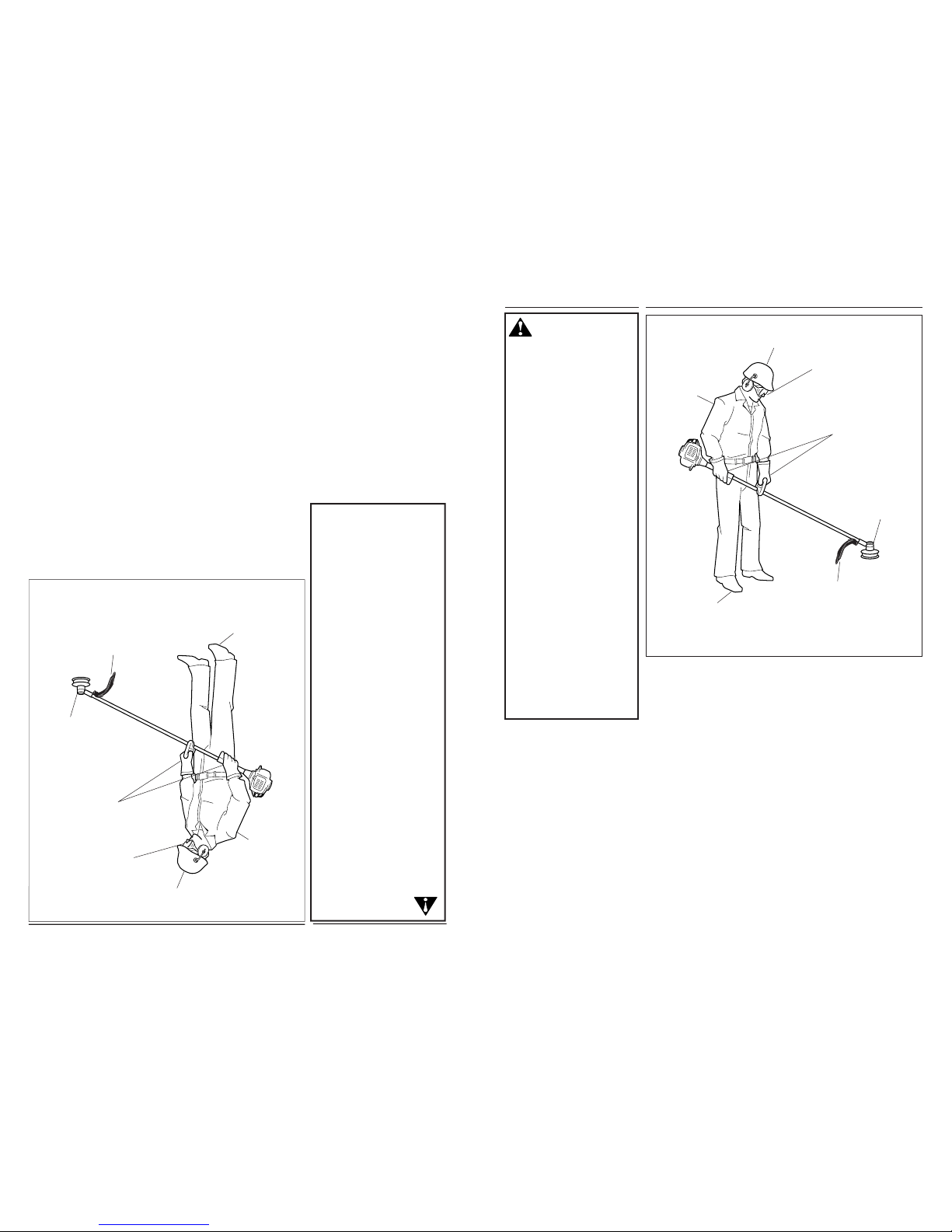
WARNING!
Use Good Judgment
ALWAYS wear eye protection to
shield against thrown objects.
NEVER run the engine when
transporting the unit.
NEVER run the engine indoors!
Make sure there is always good
ventilation. Fumes from engine
exhaust can cause serious injury
or death.
ALWAYS clear your work area of
trash or hidden debris that could
be thrown back at you or toward a
bystander.
ALWAYS use the proper cutting
tool for the job.
ALWAYS stop the engine immediately if it suddenly begins to
vibrate or shake. Inspect for
broken, missing or improperly
installed parts or attachments.
NEVER extend trimming line
beyond the length specified for
your unit.
ALWAYS keep the unit as clean
as practical. Keep it free of loose
vegetation, mud, etc.
ALWAYS hold the unit firmly with
both hands when cutting or
trimming, and maintain control at
all times.
ALWAYS keep the handles clean.
ALWAYS disconnect the spark
plug wire before performing any
maintenance work.
ALWAYS, if a saw blade should
bind fast in a cut, shut off the
engine immediately. Push the
branch or tree to ease the bind
and free the blade.
General Safety Instructions
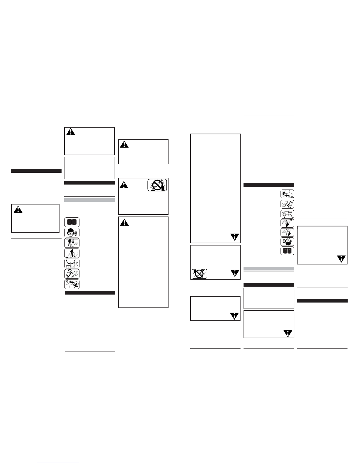
The Properly Equipped Operator
Always operate with
both hands firmly
gripping the unit.
Wear close-fitting clothing
to protect legs and arms.
Gloves offer added
protection and are strongly
recommended. Do not
wear clothing or jewelry
that could get caught in
machinery
or underbrush.
Secure hair so it is
above shoulder
level. NEVER
wear
shorts!
Wear hearing protection
devices and a broad-brimmed
hat or helmet.
Always wear eye protection such
as goggles or safety glasses.
Keep away from the rotating
trimmer line or blade at all
times, and never lift a moving
attachment above waist-high.
Wear appropriate footwear (non-skid
boots or shoes): do not wear opentoed shoes or sandals. Never
operate the unit while barefoot!
Keep a proper
footing and do not
overreach—
maintain your
balance at all times
during operation.
Always make sure
the appropriate
cutting attachment
shield is correctly
installed and in
good condition.
Figure 1
3
El Operario Debidamente Equipado
Siempre opere con
ambas manos sujetando
el mango firmemente.
Use ropa de su talla para
protejer su piernas y
brazos. Los guantes
siempre proveen
protección adicional y son
altamente recomendados.
No use ropa holgada o
joyas que puedan
atascarse en la
máquina o en la
vegetación.
Amárrese el
cabello
largo de
tal forma
que esté
sobre el nivel de los
hombros. NUNCA use
pantalones cortos.
Use un protector auditivo y un
casco o sombrero.
Siempre use protección para los
ojos tal como lentes de seguridad
para protegerse de objetos
lanzados.
Mantengase alejado de la línea
de corte o disco en rotación en
todo momento, y nunca levante
un accesorio en rotación más
arriba de su cintura.
Use calzado apropiado (botas o zapatos
antideslizantes): no use zapatos con
los dedos descubiertos o sandalias.
Nunca opere la máquina descalzo!
Mantenga una
posición segura y
nunca extienda el
cuerpo- mantenga
su balance en todo
momento durante
el uso de la
máquina.
Siempre
cerciórese de que
el protector del
accesorio de corte
esté instalado
correctamente y
que esté en buena
condición.
Figura 1
Instrucciones Generales
de Seguridad
¡Advertencia!
Use Buen Juicio
SIEMPRE use protección para
los ojos como escudo contra
objetos lanzados.
NUNCA opere el motor cuando
transporte la unidad.
NUNCA opere la unidad en el
interior! Cerciorese que siempre
haya buena ventilación. El humo o
gases del escape del motor pueden
causar serias lesiones o la muerte.
SIEMPRE mantenga su area de
trabajo libre de basura u objetos
que pueden rebotar contra usted o
contra transeúntes.
SIEMPRE use el accesorio de
corte apropiado.
SIEMPRE pare el motor
inmediatamente si repentinamente
empieza a vibrar. Inspeccione el
accesorio de corte por partes
quebradas, faltantes o instaladas
incorrectamente.
NUNCA extienda el cable de nylon
más allá de lo especificado para
su máquina.
SIEMPRE mantenga la máquina lo
más limpia posible. Mantengala
libre de vegetación, barro, etc.
SIEMPRE sujete la máquina
firmemente con ambas manos
cuando corte o recorte, y mantenga
el control en todo momento.
SIEMPRE mantenga los
mangos limpios.
SIEMPRE desconente el cable de
bujía antes de hacer mantenimiento
a la máquina.
SIEMPRE, si el disco/cuchilla se
enreda en un corte, apague el
motor inmediatamente. Saque la
rama o árbol para liberar el
disco/cuchilla.
3
Safety Labels
Figure 3
IMPORTANT
Safety and Operation Information Labels: Make sure all information labels are undamaged
and readable. Immediately replace damaged or missing information labels. New labels are
available from your local authorized Shindaiwa dealer.
T2500
This label indicates the minimum
distance between front handle
and rear grip per ANSI B175.3.
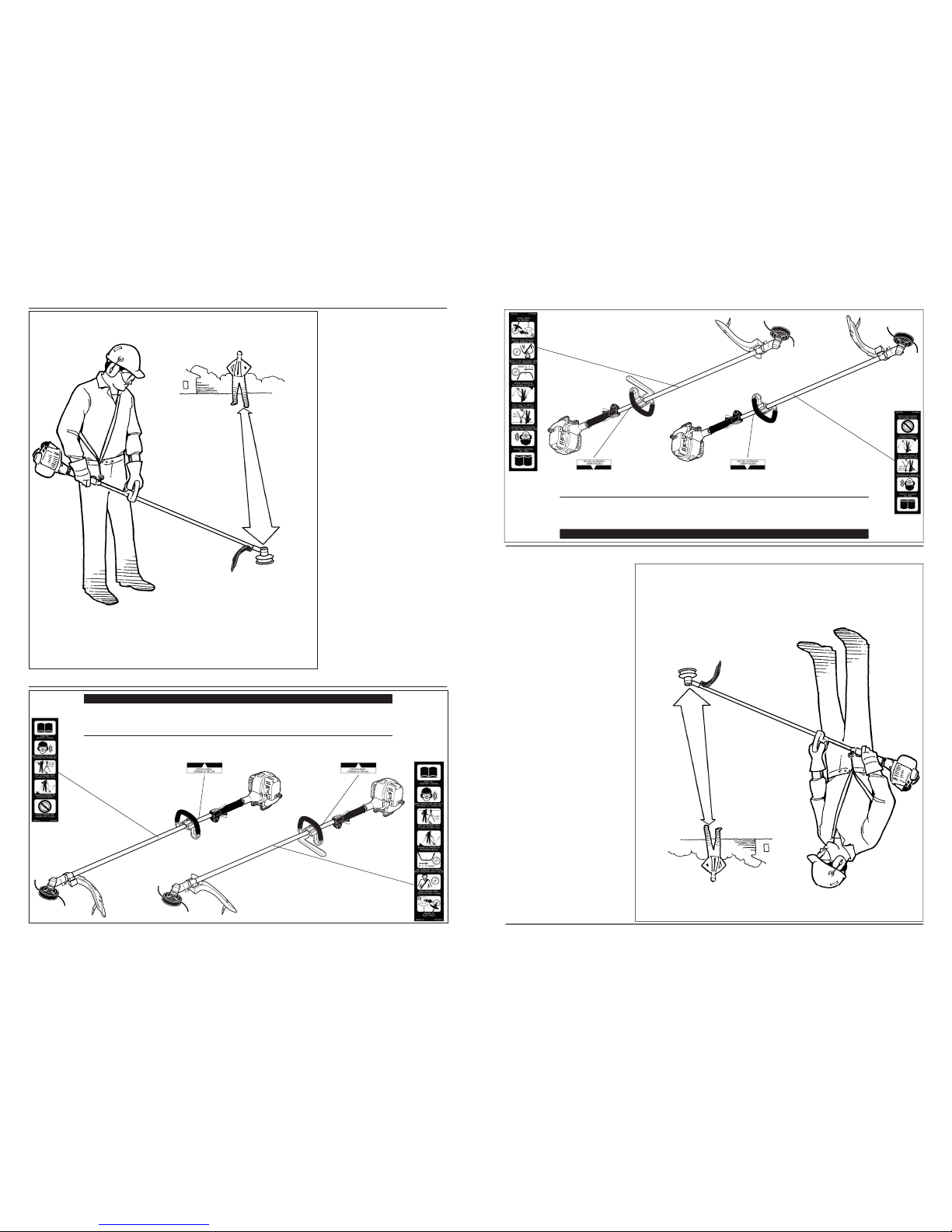
Be Aware of the Working Environment
Avoid long-term
operation in very hot or
very cold weather.
Make sure bystanders or
observers outside the 50-foot
“danger zone” wear eye
protection.
Be extremely
careful of
slippery terrain,
especially
during rainy
weather.
Always make sure
the appropriate
cutting attachment
shield is correctly
installed.
If contact is made with a hard object,
stop the engine and inspect the cutting
attachment for damage.
When operating in rocky terrain or near electric wires
or fences, use extreme caution to avoid contacting
such items with the cutting attachment.
Be constantly alert for objects and debris that could be
thrown either from the rotating cutting attachment or
bounced from a hard surface.
Reduce the risk of
bystanders being
struck by flying debris.
Make sure no one is
within 50 feet (15
meters)—that’s about
16 paces—of an
operating attachment.
Figure 2
50
FEET
T2500X
4
Etiquetas de Seguridad
Figura 3
IMPORTANTE!
Información de Operación: Asegurese que toda las etiquetas estén libres de daños y legibles.
Reemplace inmediatamente etiquetas dañadas o faltantes. Etiquetas nuevas están
disponibles en su centro de servicio local autorizado de Shindaiwa.
T2500
Esta etiqueta indica la distancia
mínima entre el mango delantero
y el mango trasero de acuerdo a
la norma ANSI B175.3
Esté Alerta del Area de Trabajo
Evite trabajar durante
largo tiempo bajo
temperaturas muy
calientes o muy frías.
Cerciórese de que los
transeúntes u observadores
estén fuera de la “zona de
peligro” de 50 píes usen
protección de ojos.
Tenga mucho
cuidado al
trabajar sobre
terrenos
resbalosos,
especialmente
en tiempo de
lluvia.
Siempre cerciórese
de que el protector
del accesorio de corte
esté correctamente
instalado.
Si hace contacto con un objeto sólido,
detenga el motor e inspeccione el
accesorio de corte en busca de daños.
Cuando trabaje en un terreno rocoso o cerca de
cables o cercas eléctricas, use extremo cuidado y
evite tocarlos con el accesorio de corte.
Esté constantemente alerta de los objetos y despojos
que puedan ser lanzados por el accesorio de corte
o rebotados.
Reduzca el riesgo de que
algún transeúnte sea
golpeado por un objeto
volante. Asegurese de que
nadie esté dentro de 50 píes
(15 metros) de distancia de
un accesorio en operación.
Esto es aproximadamente
16 pasos.
Figura 2
50 píes.
T2500X
4
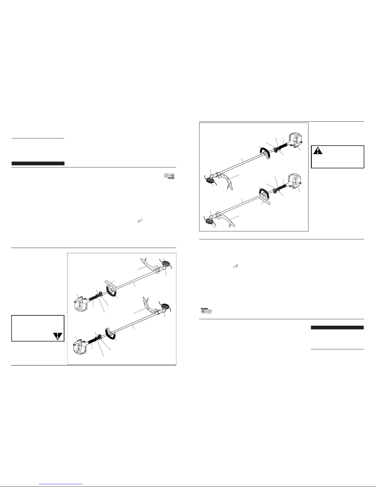
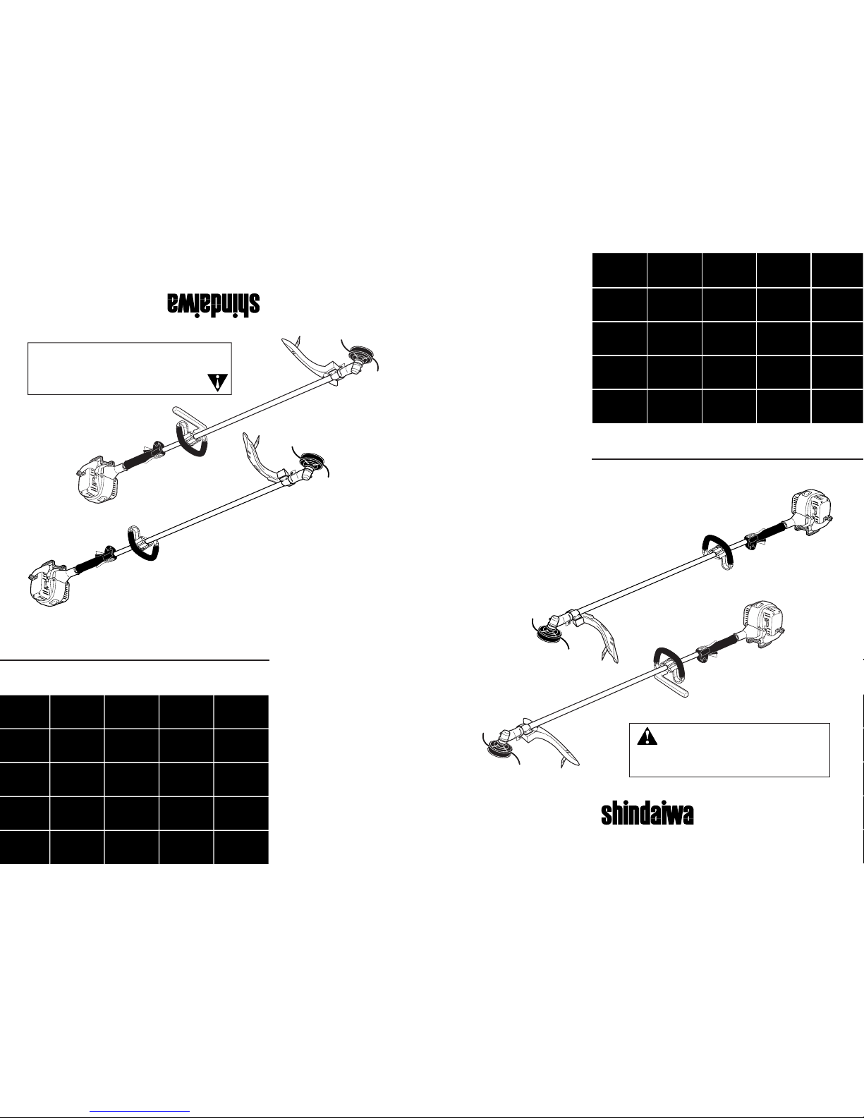
Product Description
Using the accompanying illustrations as
a guide, familiarize yourself with this
unit and its various components. See
Figure 4. Understanding your unit helps
ensure top performance, long service
life, and safer operation.
Figure 4
Specifications
T2500 dry weight
(less attachments) ............11.0 lb./5.0 kg
T2500X dry weight
(less attachments) ............11.3 lb./5.1 kg
Engine model ....................SF2500E
Engine type ....................... with Power Boost Chamber
Bore x stroke .................... 1.3 x 1.1 in./34 x27 mm
Displacement ....................1.5 cu. in./ 24.5 cc
Maximum power .............. 1.1 HP/0.8 kW
@ 7500 rpm (min
-1
)
Fuel/oil ratio .....................50:1 with ISO-L-EGD or JASO FC
class 2-cycle mixing oil*
Carburetor type ................ Walbro WYL, diaphragm-type
Fuel tank capacity ............ 20.3 oz./600 ml
Prior to Assembly
Before assembling, make sure you have
all the components required for a
complete unit and inspect unit and
components for any damage.
■ Engine and shaft assembly
■ Cutting attachment shield
Specifications are subject to change without notice.
Ignition .............................. One-piece electronic,
transistor-controlled
Spark plug ......................... NGK CMR6H
Air cleaner type ................ Non-reversible heavy-duty
filter element
Starting method ................Recoil
Stopping method .............. Slide switch
Transmission type ............Automatic, centrifugal clutch
w/bevel gear
EPA Emission
Compliance Period** ........ Category A
** The EPA emission compliance referred to on the emission compliance
label located on the engine, indicates the number of operating hours for
which the engine has been shown to meet Federal emission requirements. Category C = 50 hours (Moderate), B = 125 hours (Intermediate)
and A = 300 hours (Extended).
IMPORTANT!
The terms “left”, “left-hand”, and “LH”;
“right”, “right-hand”, and “RH”; “front”
and “rear” refer to directions as viewed
by the operator during normal
operation.
■ Cutting attachment
■ Kit containing cutting attachment
shield mounting bracket and hardware, this owner's/operator's manual
and tool kit for routine maintenance.
Tool kits vary by model and may
include a hex wrench set, a spark
plug/screwdriver combination
wrench, and a spanner.
This unit comes fully assembled with
the exception of the cutting attachment
shield and cutting attachment.
* meets or exceeds these specifications and is
recommended for all Shindaiwa products.
WARNING!
Do not make unauthorized modifications or alterations to any of
these units or their components.
T2500X
TRIMMER
Outer Tube
Trimmer Head
Grip
Cutting
Attachment
Shield
Gearcase
Handle
Throttle
Trigger
Throttle
Interlock
Ignition
Switch
Fuel
Tank
Barrier
Bar
T2500
TRIMMER
Outer Tube
Trimmer
Head
Grip
Cutting
Attachment
Shield
Gearcase
Handle
Throttle
Trigger
Throttle
Interlock
Ignition
Switch
Fuel
Tank
5
PODADORA
T2500X
Barra
Barrera
Tubo Exterior
Cabezal
Agarrador
Protector del
Accesorio de
Corte
Caja de
Engranajes
Mango
Gatillo del
Acelerador
Interruptor de
Encendido
Interruptor de
Encendido
Tanque de
Combustible
Descripción del Producto
Use las ilustraciones como guía,
familiarícese con esta unidad y sus varios
componentes. Consulte la figura 4.
Conociendo la unidad le ayudará a
obtener alto rendimiento, vida útil más
prolongada y operación con seguridad.
Figura 4
Especificaciones
T2500 Peso sin combustible
(sin accesorios) ................ 11 libras/5.0kg
T2500X Peso sin combustible
(sin accesorios) ................ 11.3 libras/5.1kg
Modelo de motor ..............SF2500E
Tipo de motor ................... C4 con recámara de impulso
Diámetro x Carrera ..........1.3 x 1.1 in./34 mm x 27 mm
Cilindrada ..........................1.5 pulg. Cúbicas/24cc
Potencia Máxima ..............1.8 HP/0.8 kW @7500 rpm (min-1)
Combustible/Aceite .........50:1 con ISO-L-EGD o JASO
FC aceite de mezcla de motor
2 tiempos
Tipo de Carburador ..........Walbro WYL, tipo diafragma
Antes de Ensamblar
Antes de ensamblar, cerciórese de que
tenga todos los componentes necesarios
para armar una máquina completa e
inspeccione la unidad y componentes en
busca de danos.
Especificaciones sujetas a cambios sin previo aviso.
Capacidad del Tanque
de Combustible................. 20.3 onzas/600 ml
Sistema de Encendido ..... Transistor controlado
por una pieza electrónica.
Bujía ...................................NGK CMR6H
Filtro de Aire .....................Elemento no reversible de
uso pesado.
Metodo de Arranque ........Recular
Metodo de Parada ............Interruptor
Tipo de Transmisión ........Automática, embrague centrífugo
con engranajes helicoidales
Periodo de Cumplimiento con Regulaciones
de Emisiones EPA* ..........Categoria A
** El cumplimiento de emisiones EPA referido en la etiqueta en el
motor, indica el número de horas de operación por la cual el motor ha
demostrado cumplir con los requisitos federales de emisiones.
Categoria C = 50 horas (Moderado), B= 125 horas (Intermedio) y
A = 300 horas (Extendido).
IMPORTANTE!
Los términos “izquierda”, “mano
izquierda”, y “LH”; “derecha”, “mano
derecha”, y “RH”, “delantera” y
“trasera”, indican direcciones desde el
punto de vista del operador durante la
operación normal de este producto.
■ Ensamblaje del motor y eje
■ Protector del Accesorio de Corte
■ Accesorio de corte
■ Kit conteniendo el soporte y
utensilios de metal para montar el
protector del accesorio de corte, este
manual del propietario/operador y
juego de herramientas para
mantenimiento rutinario. Los kits de
herramientas varian por modelo y
pueden incluir una llave hexagonal,
llave bujía y destonillador, y una
llave inglesa.
Esta unidad viene completamente
ensamblada con la excepcion del
accesorio de corte y el protector del
accesorio de corte.
* cumple o excede estas especificaciones y es
recomendada para todo los productos de Shindaiwa.
¡Advertencia!
No haga modificaciones o
alteraciones no autorizadas a
ninguna de éstas máquinas ni a
sus componentes.
PODADORA
T2500
Tubo Exterior
Cabezal
Agarrador
Protector del
Accesorio de
Corte
Caja de
Engranajes
Mango
Gatillo del
Acelerador
Interruptor de
Encendido
Interruptor de
Encendido
Tanque de
Combustible
5
3/16-1/4 inch (4-6 mm)
Throttle Freeplay
Adjust Throttle Lever Free Play
1. Loosen the air cleaner cover knob
and remove the air cleaner cover.
See Figure 7.
2. Loosen the lock nut on the cable
adjuster. See Figure 8.
XST019A
Cable
Adjuster
Assembly and Adjustments
Figure 7
Figure 8
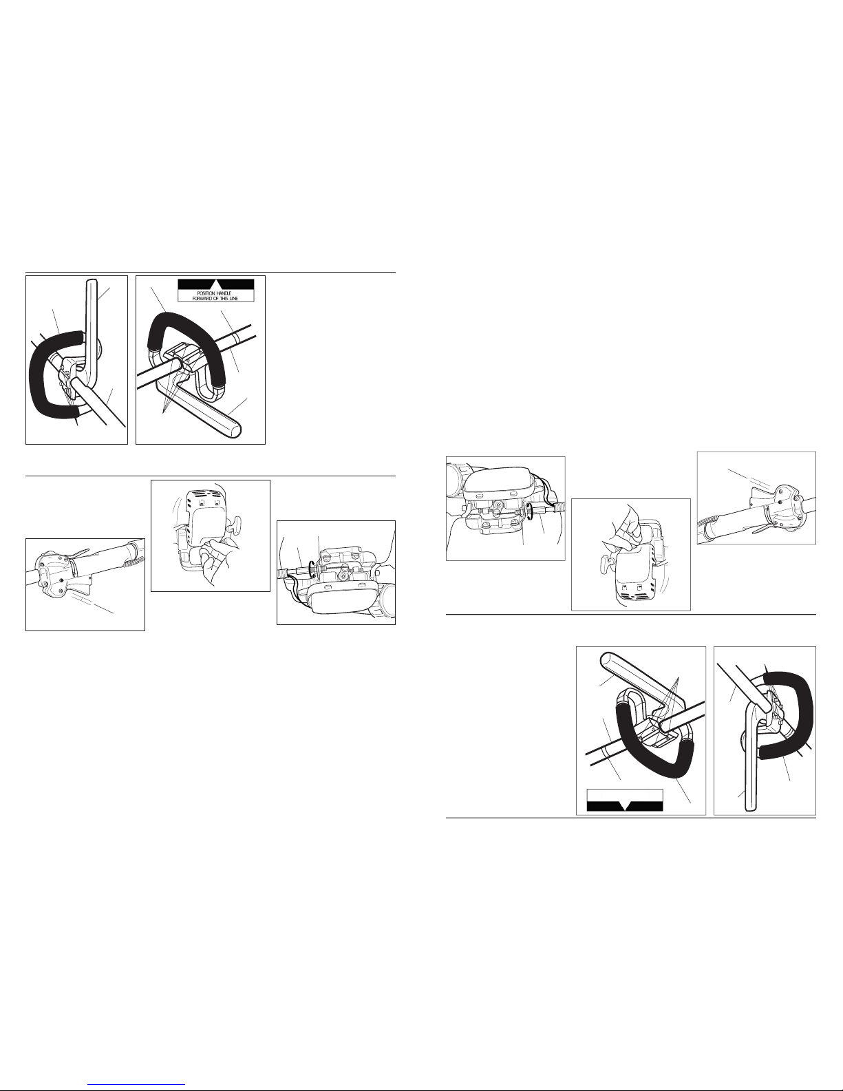
Handle.
1. The handle is attached to the outer
tube at the factory and positioned
vertically. See Figure 5.
2. Loosen the 4 socket-head capscrews
on the handle and
rotate the handle 90 degrees.
See Figure 5A.
3. Position the handle forward of the
Handle Positioning Label at the best
position for operator comfort (usually
about 10 inches ahead of the throttle
housing).
4. Secure the handle by alternately
tightening the four socket-head cap
screws in a diagonal or
“criss-cross” fashion.
Figure 5
Handle
Assembly and Adjustments
Outer Tube
Handle
Handle Positioning Label
4 Socket-head
Capscrews
The throttle lever free play should be
approxiamtely 3/16-1/4 inch(4-6 mm).
See Figure 6. Make sure that the throttle
lever operates smoothly without binding.
If it becomes necessary to adjust the
lever freeplay, follow the procedures
and illustrations that follow.
Figure 6
3. Turn the cable adjuster in or out as
required to obtain proper free play
3/16-1/4 inch(4-6 mm). See Figure 8.
4. Tighten the locknut.
Lock
Nut
5. Reinstall the air cleaner cover.
Handle
Outer
Tube
Figure 5A
4 Socket-head
Capscrews
Barrier
Bar
Barrier
Bar
6
POSICIONE EL MANGO
HACIA ADELANTE
3/16-1/4 pulgadas (4.6 mm)
Holgura del acelerador
Ajuste la holgura del acelerador
1. Afloje el botón de la tapa del filtro de
aire y retire la tapa del filtro de aire.
Consulte la figura 7.
2. Afloje la tuerca de seguridad en el
cable ajustador. Consulte la figura 8.
XST019A
Cable
ajustador
Ensamblaje y Ajustes
Figura 7
Figura 8
Mango
1. La fabrica instala el mango en el
tubo exterior y es posicionado
verticalmente. Consulte la figura 5.
2. Afloje los cuatro tornillos de cabeza
hueca y rote el mango 90 grados.
Consulte la figura 5A.
3. Posicione el mango hacia adelante a
la posición más cómoda para el
operador (usualmente a 10 pulgadas
más allá de la caja del acelerador).
4. Asegure el mango ajustando
alternadamente los cuatro tornillos
de cabeza allen en forma diagonal
o cruzada.
Figura 5
Mango
Ensamblaje y Ajustes
Tubo
Exterior
Mango
Etiqueta de posicion del mango
Tornillos de
cabeza allen
La holgura del gatillo debe ser
aproximadamente de 3/16-1/4 pulgadas
(4.6 mm). Consulte la figura 6.
Cerciórese que el gatillo de aceleración
opere suavemente sin trabarse. Si es
necesario ajustar la holgura, siga
los procedimientos e ilustraciones
a continuación.
Figura 6
3. Gire el cable ajustador hacia dentro o
fuera como sea requerido para
obtener la holgura apropiada
3/16-1/4 pulgadas (4.6 mm).
Consulte la figura 8.
4. Apriete las tuercas de seguridad.
Tuerca de
seguridad
5. Reinstale la tapa del filtro de aire.
Mango
Tubo
Exterior
Figura 5A
Tornillos de
cabeza allen
Barra
Protectora
Barra
Protectora
6
 Loading...