

Shindaiwa T230,T230X,C230 Owner's/operator's Manual
ENGLISH
SHINDAIWA OWNER’S/OPERATOR’S MANUAL
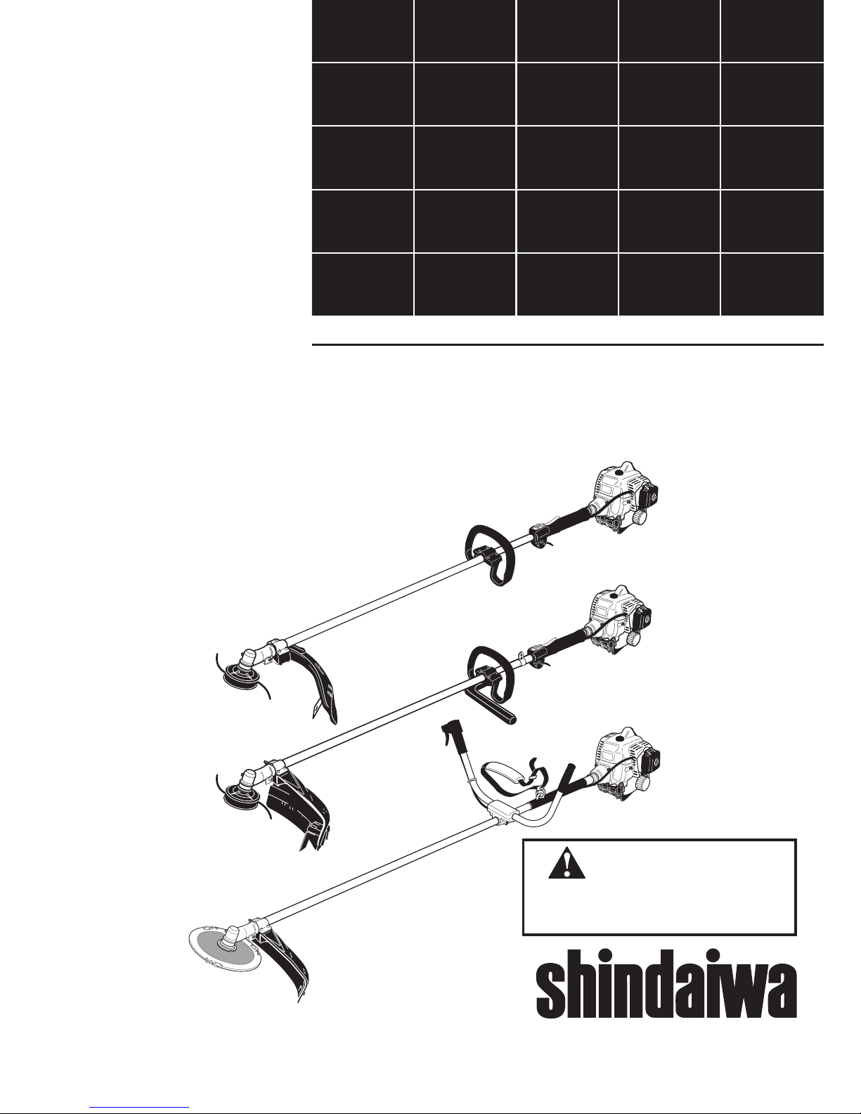
T230 GRASS TRIMMER
T230X GRASS TRIMMER
C230 BRUSHCUTTER
Part Number 62064-94013 Rev. 8/06
Minimize the risk of injury to
yourself and others! Read this
manual and familiarize yourself
with the contents. Always wear
eye and hearing protection
when operating this unit.
WARNING!
T230
T230X
C230
®
2
Contents
Introduction
PAGE
Shindaiwa 230-series hand held power
equipment has been designed and built to
deliver superior performance and reliability
without compromise to quality, comfort,
safety or durability.
Shindaiwa’s high-performance engines represent the leading edge of 2-cycle engine
technology, delivering exceptionally high
power with remarkably low displacement
and weight. As an owner/operator, you’ll
soon discover for yourself why Shindaiwa is
simply in a class by itself!
IMPORTANT!
The information contained in this owner's/
operator's manual describes units available at the time of publication.
Shindaiwa Inc. reserves the right to make
changes to products without prior notice,
and without obligation to make alterations
to units previously manufactured.
Attention Statements ...................................3
Safety Information ........................................4
Safety Labels .................................................4
Unit Description ...........................................5
Specifications ................................................5
Assembly .......................................................6
Mixing Fuel ................................................11
Starting the Engine ....................................12
Stopping the Engine ..................................12
Adjusting Engine Idle ................................13
Checking Unit Condition...........................13
Shoulder Strap ............................................13
Using the Trimmer (T230) ......................14
Using the Brushcutter (C230) ..................15
Maintenance ...............................................16
Long Term Storage ....................................19
Blade Sharpening .......................................19
Troubleshooting Guide .............................20
Emission System Warranty .......................22
Throughout this manual are special
“Attention Statements.”
WARNING!
A statement preceded by the triangular attention symbol and the word
“WARNING” contains information that
should be acted upon to prevent serious bodily injury.
CAUTION!
A statement preceded by the word
“CAUTION” contains information that
should be acted upon to prevent mechanical damage.
IMPORTANT!
A statement preceded by the word
“IMPORTANT” is one that possesses
special signicance.
NOTE:
A statement preceded by the word “NOTE”
contains information that is handy to know
and may make your job easier.
Attention Statements
IMPORTANT!
The operational procedures described in
this manual are intended to help you get
the most from unit as well as to protect
you and others from harm. These procedures are guidelines for safe operation under most conditions, and are not intended
to replace any safety rules and/or laws
that may be in force in your area. If you
have questions regarding your Shindaiwa
power tool, or if you do not understand
something in this manual, your Shindaiwa
dealer will be glad to assist you. You may
also contact Shindaiwa, Inc. at the address printed on the back of this manual.
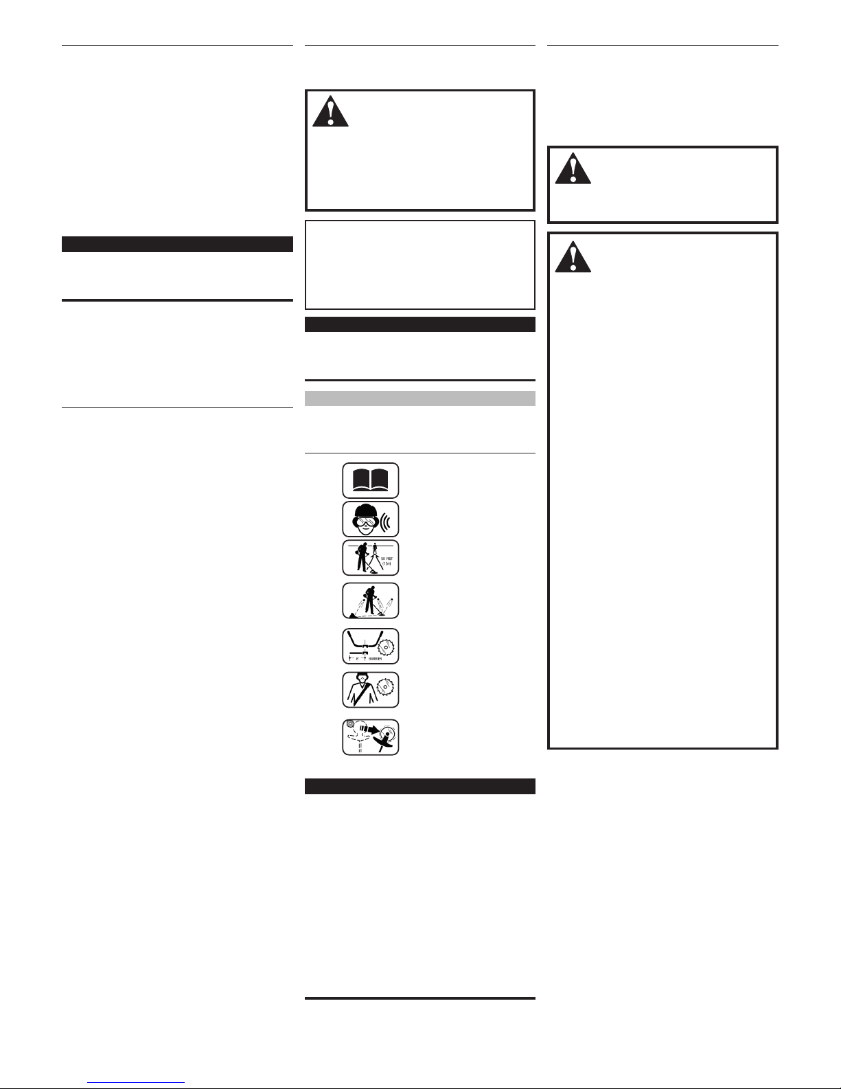
Read and follow this
operators manual.
Failure to do so could
result in serious injury.
Wear eye and hearing
protection at all times
during the operation
of this unit.
Keep bystanders
at least 50 feet (15 m)
away during operation.
Beware of thrown or
ricocheted objects.
Do not operate this unit
with a blade unless the
unit is equipped with a
Shindaiwa-approved
handlebar or barrier.
Always wear a harness
when operating this unit
with a blade. A harness
is also recommended when
using trimmer line.
If unit is used as a
brushcutter, beware of
blade thrust. A jammed
blade can cause the unit
to jerk suddenly and may
cause the operator to
lose control of the unit.
Work Safely
Trimmers and brushcutters operate at very
high speeds and can do serious damage or
injury if they are misused or abused. Never
allow a person without training or instruction to operate this unit!
WARNING!
Use Good Judgment
NEVER run the engine when transport-
ing the unit.
NEVER run the engine indoors! Make
sure there is always good ventilation.
Fumes from engine exhaust can cause
serious injury or death.
ALWAYS use the proper cutting tool for
the job.
ALWAYS stop the unit immediately if
it suddenly begins to vibrate or shake.
Inspect for broken, missing or improperly installed parts or attachments.
NEVER extend trimming line beyond
the length specied for your unit.
ALWAYS keep the unit as clean as
practical. Keep it free of loose vegetation, mud, etc.
ALWAYS hold the unit rmly with both
hands when cutting or trimming, and
maintain control at all times.
ALWAYS keep the handles clean.
ALWAYS disconnect the spark plug
wire before performing any maintenance work.
ALWAYS, if a saw blade should bind
fast in a cut, shut off the engine immediately. Push the branch or tree to ease
the bind and free the blade.
General Safety Instructions
WARNING!
Never make unauthorized attachment
installations.
3
Stay Alert
You must be physically and mentally fit to
operate this unit safely.
WARNING!
Never operate power
equipment of any kind
if you are tired or if you are under the
inuence of alcohol, drugs, medication
or any other substance that could affect
your ability or judgement.
WARNING!
Minimize the Risk of Fire!
NEVER smoke or light res near the
unit.
ALWAYS stop the engine and allow it
to cool before refueling. Avoid overlling and wipe off any fuel that may have
spilled.
ALWAYS inspect the unit for fuel leaks
before each use. During each rell,
check that no fuel leaks from around
the fuel cap and/or fuel tank. If fuel
leaks are evident, stop using the unit
immediately. Fuel leaks must be repaired before using the unit.
ALWAYS move the unit to a place well
away from a fuel storage area or other
readily ammable materials before
starting the engine.
NEVER place ammable material close
to the engine mufer.
NEVER run the engine without the
spark arrester screen in place.
The Properly Equipped Operator
ALWAYS wear a
harness when operating a
unit equipped with a blade.
ALWAYS operate with
both hands firmly gripping
the unit.
Wear close-fitting
clothing to protect legs and
arms. Gloves offer added
protection and are strongly
recommended. Do not
wear clothing or jewelry
that could get caught in
machinery or
underbrush. Secure
long hair so that
it is above shoulder
level. NEVER
wear shorts!
Wear hearing protection devices and a
broad-brimmed hat or helmet.
ALWAYS wear eye
protection such as goggles or
safety glasses to shield against
thrown objects.
When operating with a blade, make
sure the handle is positioned to
provide you with maximum
protection from contacting
the blade.
Keep away from the rotating
trimmer line or blade at all times,
and never lift a moving
attachment above waist-high.
Wear appropriate footwear (non-skid
boots or shoes): do not wear open-toed
shoes or sandals. Never work bare-
footed!
Keep a proper footing
and do not overreach.
Maintain your balance
at all times during
operation.
ALWAYS make sure the appropriate
cutting attachment shield is correctly
installed and in good condition.
Figure 1
General Safety Instructions

4
26105
Be Aware of the Working Environment (all units)
Avoid long-term operation
in very hot or ver y cold
weather.
Make sure bystanders or observers
outside the 50-foot “danger zone”
wear eye protection.
Be extremely
careful of
slippery terrain,
especially during
rainy weather.
ALWAYS make sure
the appropriate cutting
attachment shield is
correctly installed.
If contact is made with
a hard object, stop the
engine and inspect the
cutting attachment for
damage.
Be constantly alert for objects
and debris that could be thrown
either from the rotating cutting
attachment or bounced from a
hard surface.
Reduce the risk of
bystanders being struck
by flying debris. Make
sure no one is within 50
feet (15 meters)—that’s
about 16 paces—of an
operating attachment.
Beware of a coasting blade when brushcutting
or edging. A coasting blade can injure while
it continues to spin after the throttle trigger is
released or after the engine is stopped.
Figure 3
50
FEET
ALWAYS clear your work area of trash or hidden debris that could be
thrown back at you or toward a bystander. When operating in rocky terrain
or near electric wires or fences, use extreme caution to avoid contacting such
items with the cutting attachment.
Safety Labels
Figure 2
IMPORTANT!
Safety and Operation Information Labels:
Make sure all information labels are
undamaged and readable. Immediately
replace damaged or missing information
labels. New labels are available from your
local authorized Shindaiwa dealer.
T230
C230
READTHE
OPERATOR’SMANUAL
WEARHEARINGAND ANSIZ87.1
APPROVEDEYEPROTECTION
KEEPBYSTANDERSAWAY
ATLEAST 50FEET (15m)
BEWAREOF THROWNOR
RICOCHETEDOBJECTS
DONOT OPERATETHIS
MACHINEWITHA BLADE
50FEET
(15m)
19422-00028ShindaiwaInc.
This label indicates the minimum
distance between front handle and
rear grip per ANSI B175.3.
T230X
5
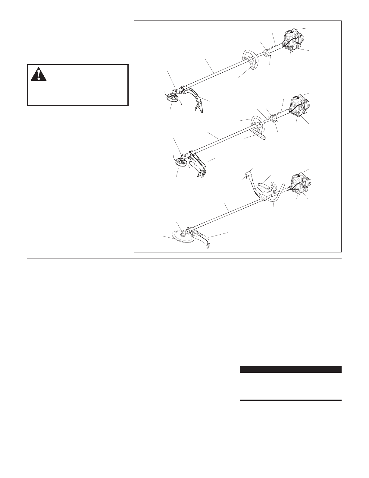
Unit Description
Using the accompanying illustrations as
a guide, familiarize yourself with this unit
and its various components. Understanding
the product helps ensure top performance,
long service life, and safer operation. See
Figure 4.
WARNING!
Do not make unauthorized modications or alterations to any of these units
or their components.
Specications
T230 Dry Weight (less attachments) .........................4.6 kg/10.2 lb.
T230X Dry Weight (less attachments).......................4.7 kg/10.4 lb.
C230 Dry Weight (less attachments) .........................4.9 kg/10.8 lb.
Engine Model ............................................................ Shindaiwa S230
Engine Type ............................. 2-cycle, vertical-cylinder, air-cooled
Bore x Stroke ...........................................32 x 28 mm/1.26 x 1.10 in.
Displacement .......................................................... 22.5 cc/1.4 cu. in.
Maximum Power Output ...... 1.1 HP (0.8 kW) @ 7500 RPM (min-1)
Fuel/Oil Ratio ..................................................... 50:1 with Shindaiwa
Premium 2-cycle mixing oil
Fuel Tank Capacity ....................................................554 ml/18.7 oz.
Carburetor Type ................................ Walbro WYL, diaphragm-type
Ignition ..........................One-piece electronic, transistor-controlled
Spark Plug .................................................................... Champion CJ8
(for EMC compliance use NGK BMR6A)
Air Cleaner Type .................. Non-reversible flocked filter element
Starting Method .........................................................................Recoil
Stopping Method ..............................................................Slide switch
Transmission Type .............................Automatic, centrifugal clutch
w/bevel gear
Prior to Assembly
Before assembling, make sure you have all
the components required for a complete
unit:
Engine assembly.
Outer tube assembly.
Cutting attachment shield.
Cutting attachment (trimmer head,
or brushcutter blade).
Correct operators handle (see page 8).
Kit containing cutting attachment
shield mounting bracket and hardware,
operator’s handle mounting bracket and
hardware, gearcase tool holder, this
manual and tool kit for routine maintenance. Tool kits vary by model and may
include a hex wrench, spanner and a
combination spark plug wrench/screwdriver.
Carefully inspect all components
for damage.
*Specifications are subject to change without notice.
IMPORTANT!
The terms “left”, “left-hand”, and “LH”;
“right”, “right-hand”, and “RH”; “front” and
“rear” refer to directions as viewed by the
operator during normal operation.
Figure 4
C230
BRUSHCUTTER
Outer Tube
Handlebar
Cutting Attachment
Shield
Shoulder
Strap
Brushcutter
Blade
Throttle
Trigger
Gearcase
Tank
Protector
Ignition
Switch
Fuel
Tank
Spark
Plug
Outer Tube
Trimmer Head
Grip
Cutting
Attachment
Shield
Gearcase
Throttle
Trigger
Tank
Protector
Ignition
Switch
Spark
Plug
Fuel
Tank
T230
GRASS TRIMMER
T230X
GRASS TRIMMER
Outer Tube
Trimmer Head
Grip
Cutting Attachment
Shield
Gearcase
Throttle
Trigger
Tank
Protector
Ignition
Switch
Spark
Plug
Fuel
Tank
Handle
(for trimmer use only)
Barrier
Hanger
Handle
6
Driveshaft/Powerhead All Models
Grip
Spark Plug
Main
Shaft
Tube
Clamp
Outer Tube
T230
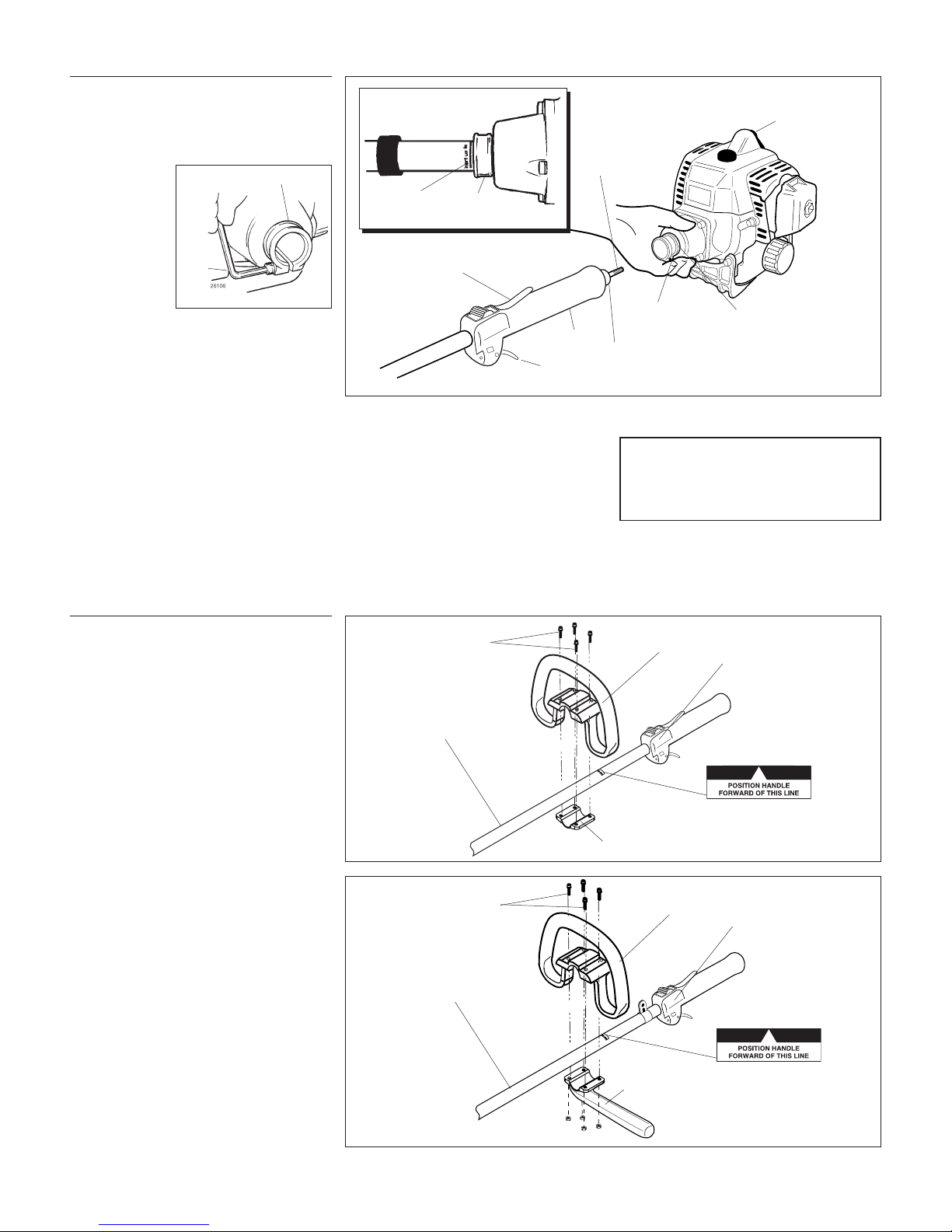
1. Place the powerhead on a clean, flat surface, spark plug facing up. See Figure 6.
2. Use the
4 mm hex
wrench to
loosen the
tube clamp
screw.
3. Add some
moly-type
EP grease to
the splines
on the end of the mainshaft.
4. Slide the outer tube into the tube clamp
until the tube bottoms. If installation is
difficult, rotate the outer tube or mainshaft slightly until you feel the mainshaft
splines engage with the powerhead.
5. Position the outer tube so that the ignition switch is facing up and the throttle
trigger is down.
Tube Clamp
Connect the Outer Tube
to the Powerhead.
CAUTION!
Do not force the shaft tube into the
powerhead! Excessive force can damage the shaft tube and mainshaft.
Clamp must fit next to line
on outer-tube decal
Decal
Clamp
C230 Brushcutter
Clamp
Screw
Figure 6
Figure 5
Assembly
Throttle
Trigger
Ignition
Switch
Hex
Wrench
Figure 6A
T230 Slide the outer tube into the
powerhead until the throttle grip
just contacts the tube clamp.
C230 Slide the outer tube into the
powerhead until the installation
decal aligns with the tube clamp.
See Figure 6A.
6. Tighten the clamp screw firmly.
Assembly
Handle
T230 - Connect the Handle to
the Outer Tube.
1. Position the handle on the outer tube
forward of Handle Positioning Label as
shown in Figure 7.
2. Install the mounting bracket with the
socket head cap screws. Tighten the
screws finger-tight ONLY at this time.
3. Locate the handle in the best position
for operator comfort (usually about 10
inches ahead of the throttle housing).
4. Secure the handle by alternately tightening the four socket-head screws in a
diagonal or “crisscross” fashion.
Outer Tube
Socket-head
Caps Screws
Handle
Mounting Bracket
Throttle
Assembly
Figure 8
Handle Positioning Label
T230X - Connect the Handle to
the Outer Tube.
1. Position the handle on the outer tube
forward of Handle Positioning Label as
shown in Figure 8.
2. Install the barrier bar with the socket
head cap screws and nuts. Tighten the
screws finger-tight only at this time.
3. Locate the handle in the best position
for operator comfort (usually about 10
inches ahead of the throttle housing).
4. Secure the handle by alternately tightening the four socket-head screws in a
diagonal or “crisscross” fashion.
Figure 7
Outer Tube
Socket-head
Caps Screws
Handle
Barrier
Throttle
Assembly
Handle Positioning Label
7
23013
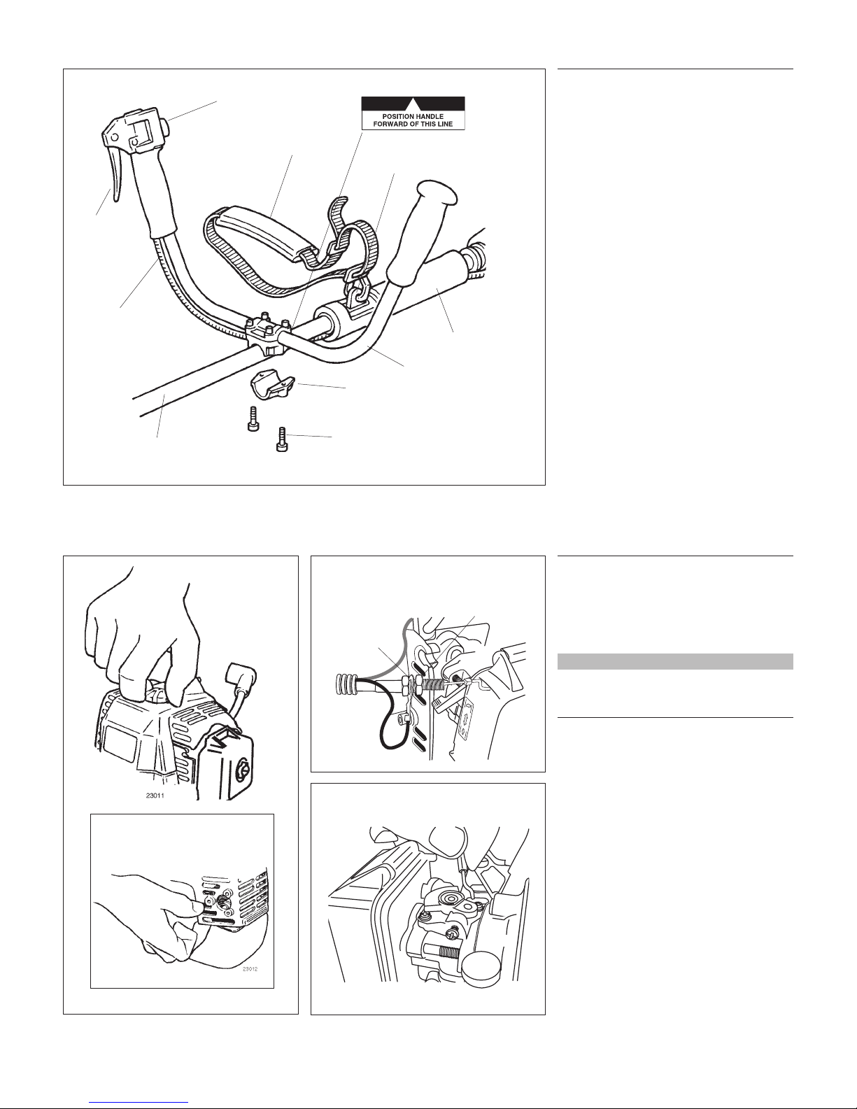
Assembly
Throttle Linkage and Ignition Leads All Models
Remove the Cylinder Cover.
1. Remove the cap from the spark plug.
2. Loosen the black cylinder cover knob
(about a dozen full turns are required),
and then lift off the cylinder cover.
NOTE:
If the cover binds on the muffler outlet tube,
pull gently on the corner of the cover as
shown (see inset).
Connect the Throttle Cable.
1. Route the ribbed cable over the tube
clamp to the top left side of the engine.
2. Install the black wire between the two
cable adjuster nuts as shown. See
Figure 11.
3. Connect the S-shaped end of the throttle
cable to the throttle lever on top of the
carburetor. See Figure 12.
Install the black wire
between the two cable
adjuster nuts.
Connect the
throttle cable
Ignition
Ground
Lead
Cable Adjuster Nut
Figure 11
Figure 12
23014
Loosen the
cylinder cover
knob and
disconnect the
spark plug cap
Lift the corner of
the cover
Figure 10
Handle Positioning Label
Assembly
Handlebar C230
Assemble the Handlebar.
1. Position the handle over the outer tube.
See Figure 9. Make sure the throttle lever is on the right-hand side of the outer
tube.
2. Attach the handle mounting bracket
using the two socket-head cap screws.
Tighten the screws finger-tight ONLY at
this time.
3. Locate the handle forward of the Handle
Positioning Label at the best position for
operator comfort.
4. Using the hex wrench, securely tighten
the two handlebar cap screws.
5. Route the ribbed throttle cable tube
along the handlebar and outer tube. See
Figure 9. Install the protector sleeve on
the outer tube.
Outer Tube
Mounting Bracket
Socket-Head
Cap Screw
Throttle
Cable
Handlebar
Protector Sleeve
Figure 9
Ignition Switch
Throttle
Trigger
Hanger
Shoulder Strap
8
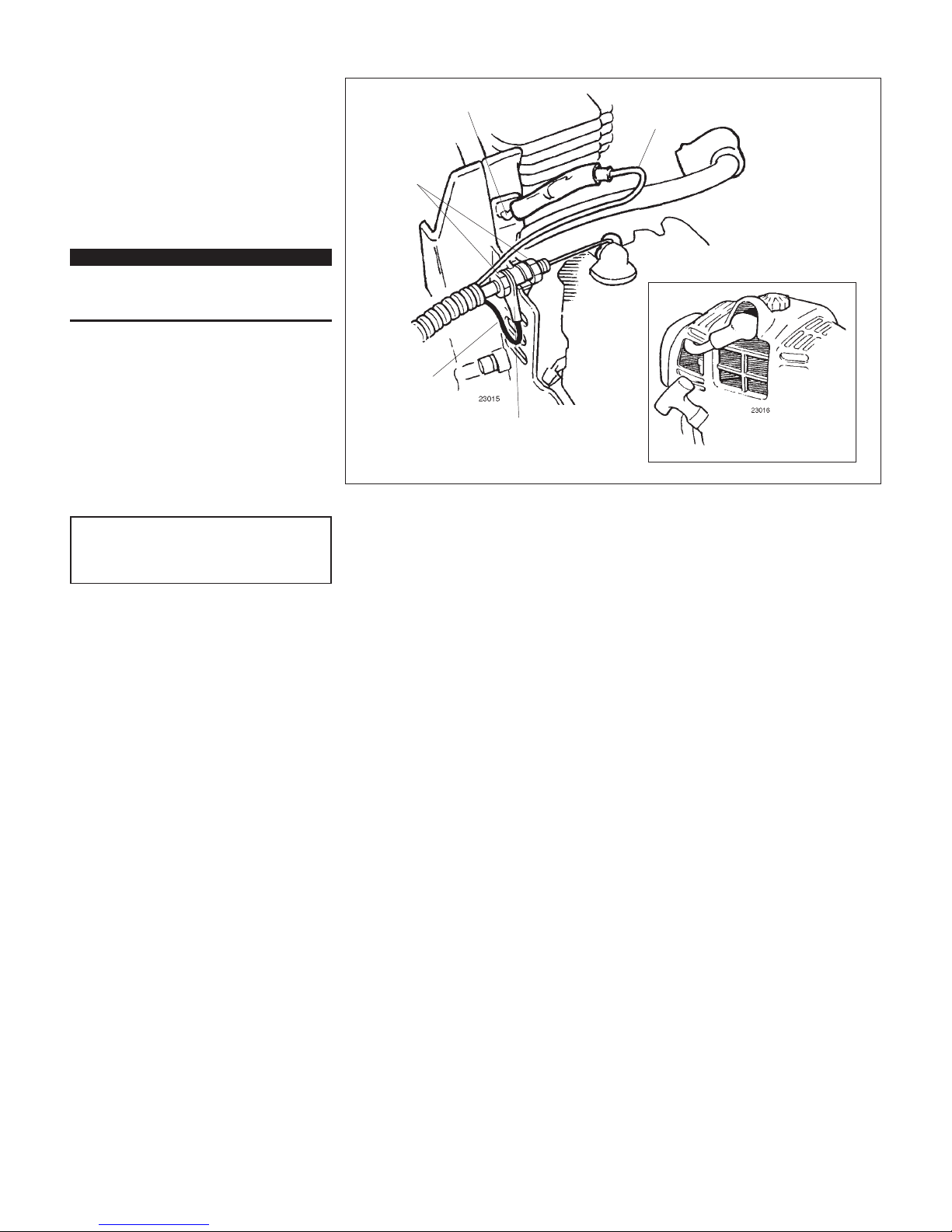
Assembly
Throttle Linkage and Ignition Leads All Models
Ground Wire
Terminal
Ground
Wire
Assemble and Adjust
the Throttle Cable.
1. Insert the throttle-cable housing into the
notch on the fan cover, and clamp the
ground wire terminal between the fan
cover and the outer cable adjuster nut.
See Figure 13.
2. Tighten the two throttle cable adjuster
nuts.
IMPORTANT!
Adjust and tighten the cable nuts to allow
approximately 1/4-inch free play at the
throttle trigger.
CAUTION!
Routing of wiring must not interfere with
throttle operation.
Figure 13
Reinstall the Spark
Plug Cap
Black Ignition
Wire
Red Wire
Cable Adjuster
Nuts
3. Using finger pressure only, connect
the black ignition wire from the cable
tube to the red ignition wire on the
powerhead. Wire routing must be as
shown in the illustration with the black
wire located away from the throttle cable
and carburetor linkage.
4. Reinstall the engine cover and tighten
the captive engine cover screw.
5. Reinstall the spark plug boot.
 Loading...