

Shindaiwa RS41 Owner's Manual
MODEL
MODEL
MODELMODEL
RS41
RS41
RS41RS41
OWNER’S MANUAL
OWNER’S MANUAL
OWNER’S MANUALOWNER’S MANUAL
ASSEMBLY INSTRUCTIONS
ASSEMBLY INSTRUCTIONS
ASSEMBLY INSTRUCTIONSASSEMBLY INSTRUCTIONS
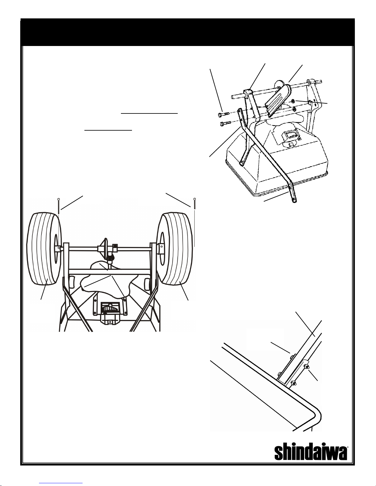
1.
Remove the spreader and components from
1/4-20 x 1 1/2”
Hex Bolt
Leg Frame
the carton. Turn spreader upside down. Insert
(2) 1/4-20 x 1 1/2” hex bolts through the
flattened end of handle brace, frame and leg as
shown. Install hex nuts but do not tighten.
1/4-20
Hex Nut
Repeat on opposite side. Make sure braces are
parallel and tighten all nuts.
BRACE MUST BE
INSTALLED ON THE
OUTSIDE OF FRAME
Drive
Wheel
5/32 x 2”
Cotter Pin
VIEWED FROM REAR OF SPREADER
1/8 x 1”
Cotter Pin
2. Slide wheels onto axle with the longer
portion of the wheel facing the frame. The
wheels are identical to ease assembly.
Secure free turning wheel with (1) 1/8 x 1”
cotter pin and (1) 5/32 x 2” cotter pin on the
drive wheel.
Free Turning
Wheel
Handle Brace
Handle
Tube
1/4-20 x 2”
Hex Bolt
3. Turn spreader upright and install handle
tube between braces. Secure with (2) 1/4-20
x 2” hex bolts and nuts. Tighten handle brace
nuts installed in step 1.
1/4-20 Hex
Nut

ASSEMBLY, CONTINUED
ASSEMBLY, CONTINUED
ASSEMBLY, CONTINUEDASSEMBLY, CONTINUED
4. Feed control knob/wire through the
T-handle until spring touches the round
hole. CAUTION: Do Not Compress Spring
At This Time. Feed wire through the
square handle tube. Be sure wire passes
above the bolts in the handle brace.
Secure T-handle to the tube with (1) 1/4-20
x 2” hex bolt. (2) washers, and (1) hex nut
in the bottom hole, and (1) 1/4-20 x 2 1/4”
hex bolt, (2) washers, and (1) hex nut in
the top hole as shown. Remove caution
label and push the thumb release toward
the center and push down knob and shutoff
spring until knob latches.
Wire Clip
1/4-20 x 2 1/4”
Bolt & Washer
CAUTION: ONCE KNOB IS LATCHED,
DO NOT MOVE THUMB RELEASE UNTIL
YOU HAVE COMPLETED STEP #5.
Remove Caution
Label
Thumb
Release
Control Knob &
Wire Assembly
Spring
1/4-20 Hex
Nut & Washer
5. Slide wire retaining clip onto wire as shown.
Insert wire through hole shutoff plate. Slide wire
retaining clip over shutoff plate and wire until the
clip locks into place.
Wire
6.
Install gear cover assembly over gears and secure
with (2) #6-32 screws. The RS41 spreader should
now be completely assembled and ready for use.
Slide handle grips onto handle. Soapy water will ease
installation. (Do not use petroleum based products.)
Shutoff Plate
Handle Grip
Handle Grip
#6-32 Screw #6-32 Screw
 Loading...