

Shindaiwa X7502235300, PB270 User Manual
SHINDAIWA OWNER’S/OPERATOR’S MANUAL
PB270 POWERBROOM
X7502235300
05/10
WARNING!
Minimize the risk of injury to yourself and others! Read this
manual and familiarize yourself with the contents. Always wear
eye and hearing protection when operating this unit.
Introduction
The Shindaiwa PB270 PowerBroom is
designed and built to deliver superior
performance and reliability without
compromise to quality, comfort, safety
or durability.
Shindaiwa engines represent the leading
edge of high-performance engine
technology, delivering exceptionally
high power with remarkably low
displacement and weight. As an owner/
operator, you’ll soon discover for
yourself why Shindaiwa is simply in a
class by itself!
IMPORTANT!
The information contained in these
instructions describes units available at
the time of publication.
Echo,Inc. reserves the right to make
changes to products without prior
notice, and without obligation to
make alterations to units previously
manufactured.
WARNING!
The engine exhaust from
this product contains chemicals
known to the State of California
to cause cancer, birth defects or
other reproductive harm.
Contents
Safety .................................................... 3
Product Description ............................ 5
Specifications ....................................... 5
Assembly .............................................. 6
Mixing fuel ........................................... 8
PAGE
Filling the fuel tank ............................. 8
Starting the Engine ............................ 9
Stopping the Engine ......................... 10
Adjusting Engine Idle ....................... 10
Checking Unit Condition.................. 10
PAGE
Operating ........................................... 11
Maintenance ...................................... 12
Long Term Storage ........................... 15
Troubleshooting Guide .................... 16
Warranty Statement .......................... 19
PAGE
IMPORTANT!
The operational procedures described in this manual are intended to help you get the most from this unit as well as to protect
you and others from harm. These procedures are guidelines for safe operation under most conditions, and are not intended
to replace any safety rules and/or laws that may be in force in your area. If you have questions regarding your PowerBroom,
or if you do not understand something in this manual, contact your local authorized Shindaiwa dealer. You may also contact
Shindaiwa Inc. at the address printed on the back of this Manual.
Attention Statements
Throughout this manual are special
“attention statements”.
DANGER!
A statement preceded by
the triangular attention symbol and
the word “DANGER” contains information that should be acted upon to
prevent serious injury or death.
by the triangular attention symbol
and the word “WARNING” contains information that should be
acted upon to prevent serious bodily injury.
A statement preceded by the word
“IMPORTANT” is one that possesses
special significance.
WARNING!
A statement preceded
IMPORTANT!
CAUTION!
A statement preceded by the
word “CAUTION” contains information that should be acted upon
to prevent mechanical damage.
NOTE:
A statement preceded by the word
“NOTE” contains information that is
handy to know and may make your job
easier.
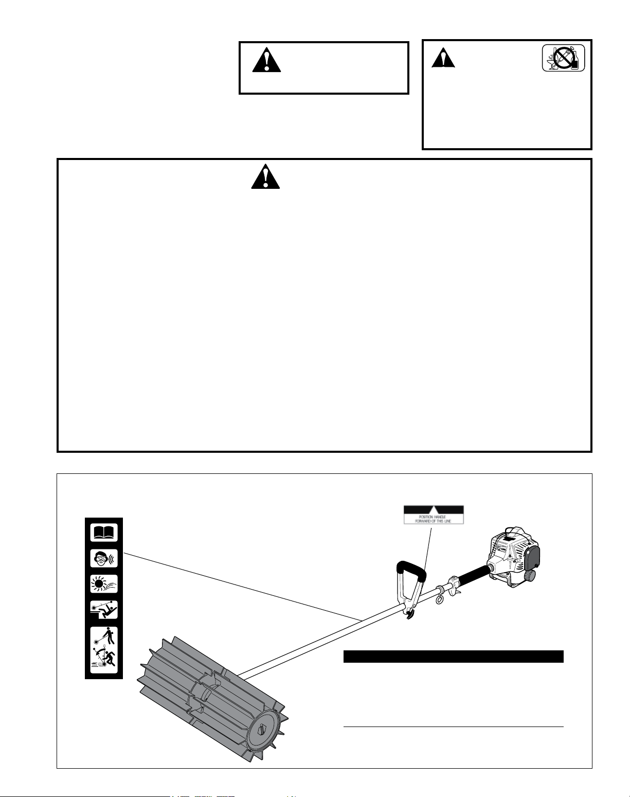
Warning and operational labels
Read and follow this manual,
make sure anyone using the
pruner does likewise. Failure
to do so could result in serious
personal injury or machine failure. Keep this manual for future
reference.
Always wear a hard hat to reduce the risk of head injuries
during operation of this machine. In addition, always wear
eye and hearing protection.
Shindaiwa recommends wearing a face shield as additional
face and eye protection.
2
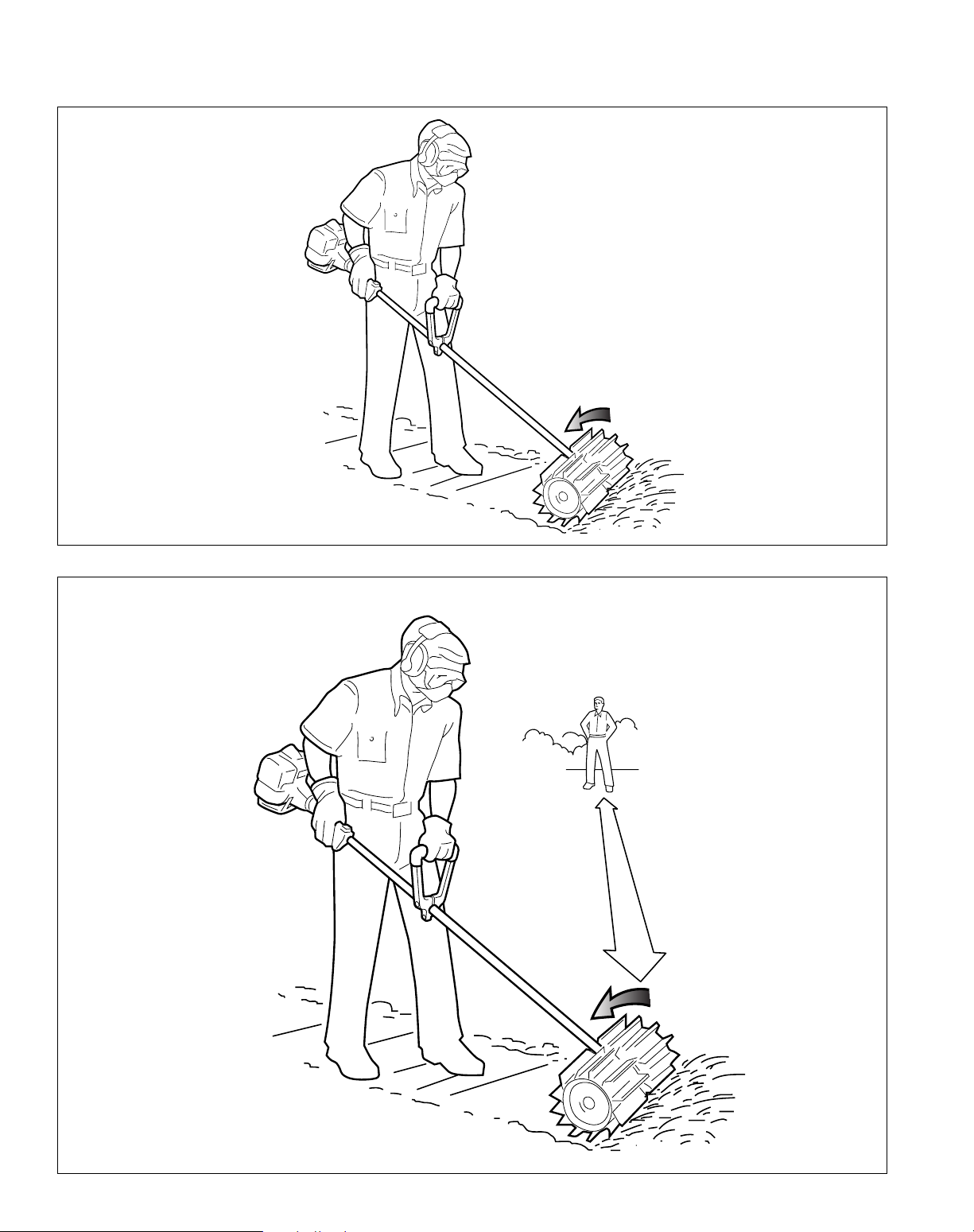
Beware of thrown objects. Keep
bystanders at least 15 M (50
feet) away during operation.
Do not use on unguarded elevated surfaces.
Maintain a shallow working
angle and avoid moving toward
the vertical.
Safety
READ THE
OPERA TOR’S MANU AL.
WEAR HEAR ING AN D ANSI Z87. 1
APPROVED EYE PROTE CTION .
BEWARE OF THRO WN
DIRT AND DEBR IS.
MAINTAIN A
SHALLOW
WORKING
ANGLE…
DO NOT U SE ON UNGU ARDED
ELEVA TED SU RFACES.
…AVOID MO VING TOWARD
VERTICAL .
80267Shindaiwa Inc .
Work Safely
A PowerBroom operates at very high
speeds and has the potential to do serious
damage if misused, abused or mishandled.
To reduce the risk of injury, you must maintain control at all times, and observe all
safety precautions during operation. Never
permit a person without training or instruction to operate this machine!
Sweeper belts may move when ■
starting engine. Place sweeper
belts on a smooth level surface
when starting.
■
Always make sure the PowerBroom attachment is properly
installed and rmly tightened
before operation.
■
Always wear eye protection to
shield against thrown objects.
■
Never modify or disable any of the
unit’s safety devices.
■
Do not make unauthorized modications to this unit.
■
Make sure there are no missing or
loose fasteners, and that the ignition switch and throttle controls are
working properly.
WARNING!
Never make unauthorized
attachment installations.
Stay Alert
You must be physically and mentally fit to
operate this unit safely.
WARNING!
Use Good Judgement
■
Do not operate the unit with the
mufer removed.
■
NEVER operate this unit indoors.
Operate this unit only in a well ventilated area. Be aware of carbon
monoxide poisoning. Exhaust gases
and lubrication oil mist can cause
serious injury or death.
■
Always hold the machine rmly with
both hands when sweeping, and
maintain control at all times.
■
Always stop the engine immediately
and check for damage if you strike a
foreign object or if the unit becomes
tangled. Do not operate with broken
or damaged equipment.
■
Always clear your work area of trash
or hidden debris to help ensure
good footing.
WARNING!
Never operate power equipment of any kind
if you are tired or if you are under
the inuence of alcohol, drugs,
medication or any other substance
that could affect your ability or
judgement.
Always use genuine Shindaiwa
■
parts and accessories when
repairing or maintaining this unit.
■
Stop the unit immediately if it
suddenly begins to vibrate or
shake. Inspect for broken, missing or improperly installed parts or
attachments.
■
Never transport the unit nor set
it down with the engine running.
An engine that’s running could be
accidentally accelerated causing
the drum assemblies to rotate.
■
Always disconnect the spark plug
wire before performing any maintenance work.
■
Always maintain this unit according to this owner’s manual and
follow the recommended scheduled maintenance.
Safety Labels
This label indicates the minimum distance between
front handle and rear grip per ANSI B175.3.
IMPORTANT!
Safety and Operation Information Labels: Make
sure all information labels are undamaged and readable. Immediately replace damaged or missing
information labels. New labels are available from
your local authorized Shindaiwa dealer.
3
15 M
Safety (continued)
The Properly Equipped Operator
Always protect yourself from hazards
such as thorny brush and ying debris
by wearing gloves and close tting
clothing that covers arms and legs.
Never wear shorts. Don’t wear loose
clothing or items such as jewelry that
could get caught in machinery or
underbrush. Secure long hair so it is
above shoulder level.
Keep a proper footing and do not
overreach—maintain your balance
at all times during operation.
Wear sturdy footwear with nonslip
soles to provide good footing. Steeltoed safety boots are recommended.
Never operate unit bare-footed!
Always wear eye and hearing protection.
Shindaiwa recommends wearing a face shield as
additional face and eye protection.
Always operate with both hands
rmly gripping the unit.
Keep away from rotating
sweeper belts or bristles at
all times, and NEVER lift a
moving attachment above
waist-height.
Be Aware of the Working Environment
Be careful when operating on a slope or on slippery
terrain, especially during rainy weather or when pulling
debris toward you.
If the drum assemblies jam, switch the
engine OFF and inspect the drums,
axles and gearcase for damage.
Do not use this unit on
rooftops or elevated surfaces
When transporting the unit in a
vehicle, tie it down securely to
prevent damage and fuel spillage.
Never operate the PowerBroom around
objects that could tangle in the drums
and cause loss of control.
Never allow the engine to run at
high RPM without a load. Doing
so could damage the engine.
Be constantly alert for objects and debris that could be
thrown either from the sweeper belts or bounced from a
hard surface.
ALWAYS clear your work area of trash or
hidden debris that could be thrown back at you
or toward a bystander. When operating in rocky
terrain or near electric wires or fences, use
extreme caution to avoid contacting such items
with the sweeper belts.
Keep bystanders
at least 15 meters
away from the unit
while operating
to reduce the risk
of being struck by
thrown debris.
Keep the unit as clean as
possible. Keep it free of loose
vegetation, mud, etc.
Maintain a low working angle and
avoid steep angles of operation.
A steep working angle risks loss
of control of the machine.
Transport the
machine with the
engine OFF.
Always keep the
handles clean.
4
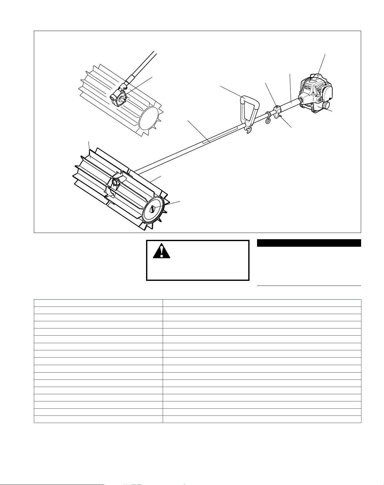
Product Description
Gearcase
Spark Plug
PB270
Grip
Ignition Switch
Handle
Sweeper Belt
Using the illustration as a guide, familiarize yourself with your machine and
its various components. Understanding your machine helps ensure top performance, long service life and safer
operation.
Outer Tube
Sweeper ns
Sweeper Drum
WARNING!
Do not make unauthorized
modications or alterations to any
of these units or their components.
Fuel Tank
Tank protector
Throttle
Trigger
IMPORTANT!
The terms “left”, “left-hand”, and
“LH”; “right”, “right-hand”, and “RH”;
“front” and “rear” refer to directions as
viewed by the operator during normal
operation.
Specications
Engine Model S270
Engine Type 2-cycle, vertical-cylinder, air-cooled
Dry Weight (less sweepers) 5.2 kg/11.5 lb.
Dry Weight (Including sweepers) 9.8 kg/21.5 lb.
Bore x Stroke 34 x 30 mm/1.34 x 1.18 in.
Displacement 27.2 cc/1.7 cu. in.
Maximum Power Output 1.5 HP (1.1 kW) @ 7500 min
Fuel/Oil Ratio 50:1 with Shindaiwa Premium 2-cycle mixing oil
Fuel Tank Capacity
660 ml/22.3 oz..
Carburetor Type TK, diaphragm-type
Ignition One-piece electronic, transistor controlled
Spark Plug Champion CJ8Y / NGK BPMR7A
Air Cleaner Type Foam element
Starting Method Recoil
Stopping Method Slide switch
Transmission Type Automatic, centrifugal clutch w/worm gear
EPA Emission Compliance Period* Category A
*Specifications are subject to change without notice.
*The EPA emission compliance period referred to on the emission compliance label located
on the engine, indicates the number of operating hours for which the engine has been shown
to meet Federal emission requirements. Category C = 50 hours (Moderate), B = 125 hours
(Intermediate) and A = 300 hours (Extended)
-1
5
Assembly
Prior to assembly
Before assembling, make sure you have all
the components required for a complete
unit:
Engine assembly ■
Outer tube assembly ■
Drum kit with gearcase ■
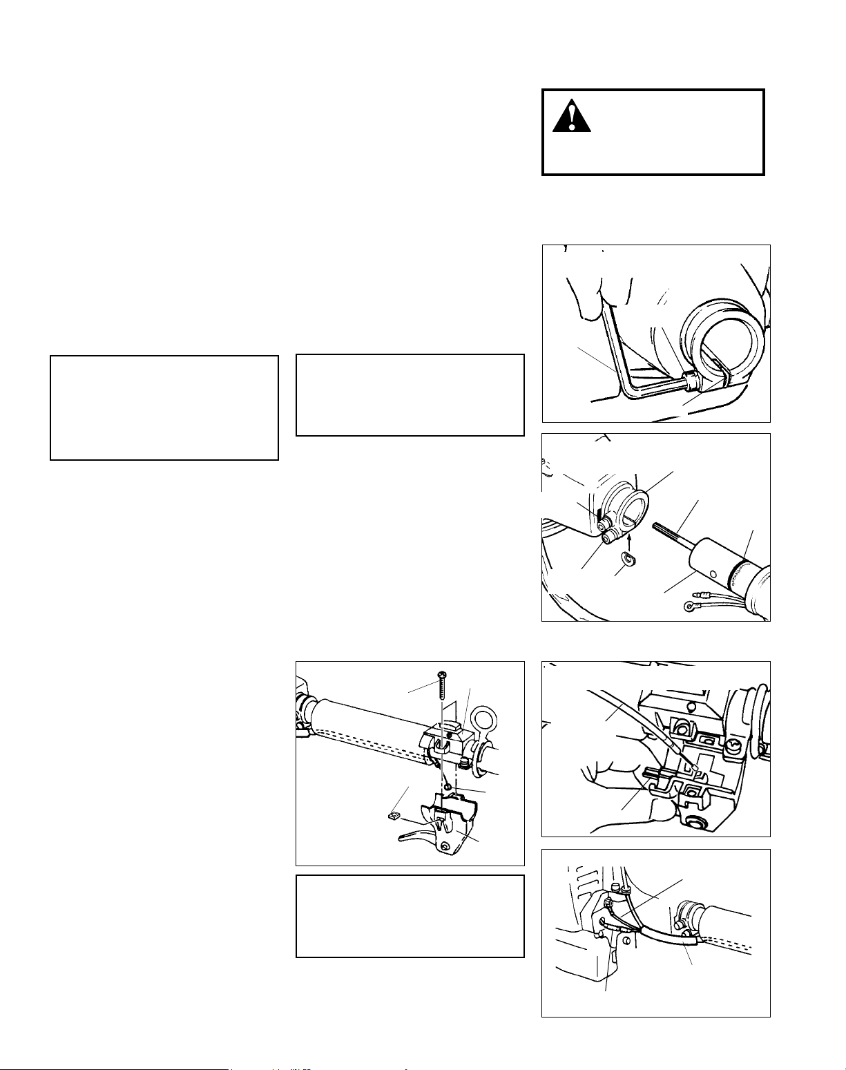
Connect the Outer Tube to the Powerhead
Place the powerhead on a clean, flat 1.
surface, spark plug facing up.
Use the 4mm hex wrench to loosen 2.
the index screw and tube clamp
screw. Verify that the D-shaped shim
washer is positioned as shown
Kit containing operator’s handle, ■
hardware, owner/operator's manual,
tool kit for routine maintenance. Tool
kits vary by model and may inclue a
hex wrench, spanner, and a combination spark plug wrench/screwdriver.
■
Carefully inspect all components for
damage before assembling.
Position the outer tube so that the 5.
ignition switch is facing up and the
throttle trigger is down.
Slide the outer tube into the power-6.
head until the throttle grip just contacts the tube clamp.
WARNING!
Do not make unauthorized
modications or alterations to your
pruner or its components.
Loosen the index screw and
tube clamp screw
Tube Clamp
Hex
Wrench
Screw
CAUTION!
Do not remove the D-shaped shim
washer! The shim washer prevents
damage from overtightening the
tube clamp screw.
Add some moly-type EP grease 3.
to the splines on the end of the
mainshaft.
Slide the outer tube into the tube 4.
clamp until the tube bottoms. If installation is difficult, rotate the outer tube
or mainshaft slightly until you feel
the mainshaft splines engage with the
powerhead.
Throttle Cable and Ignition Leads
Unscrew the two throttle lever cover 1.
screws, and then separate the throttle control halves as shown.
Working from the powerhead, push 2.
the throttle cable through the passageway in the base of the shaft tube
grip.
Insert the throttle cable end into the 3.
molded receptacle in the throttle
lever, and then lay the cable wire in
the molded slot in the throttle body.
In the reverse order of removal, reas-4.
semble the throttle body and cover
on the shaft tube.
Plug the red ignition lead from the 5.
shaft tube into the red lead from
the powerhead, and then connect
the black grounding wire to the
powerhead.
CAUTION!
Do not force the shaft tube into
the powerhead! Excessive force
can damage the shaft tube and
Tighten the clamp screw firmly.7.
Cover
Throttle
cable
Throttle
assembly
Unscrew and
separate the
throttle control
halves
Cover
screw
Nut
CAUTION!
Overtightening the throttle assembly
screws can permanently damage
the plastic throttle components!
Shim Washer
Insert outer tube into
powerhead
Index
Screw
Clamp
Screw
Insert the throttle cable end into the
molded receptacle
Throttle cable
Connect ignition leads
Shim
Washer
Molded
receptacle
Outer
Tube
Tube
Clamp
Main
Shaft
Ground lead
(black wire)
Nylon tube
Installation
Decal
Ignition lead (red
wire)
6
Assembly (continued)
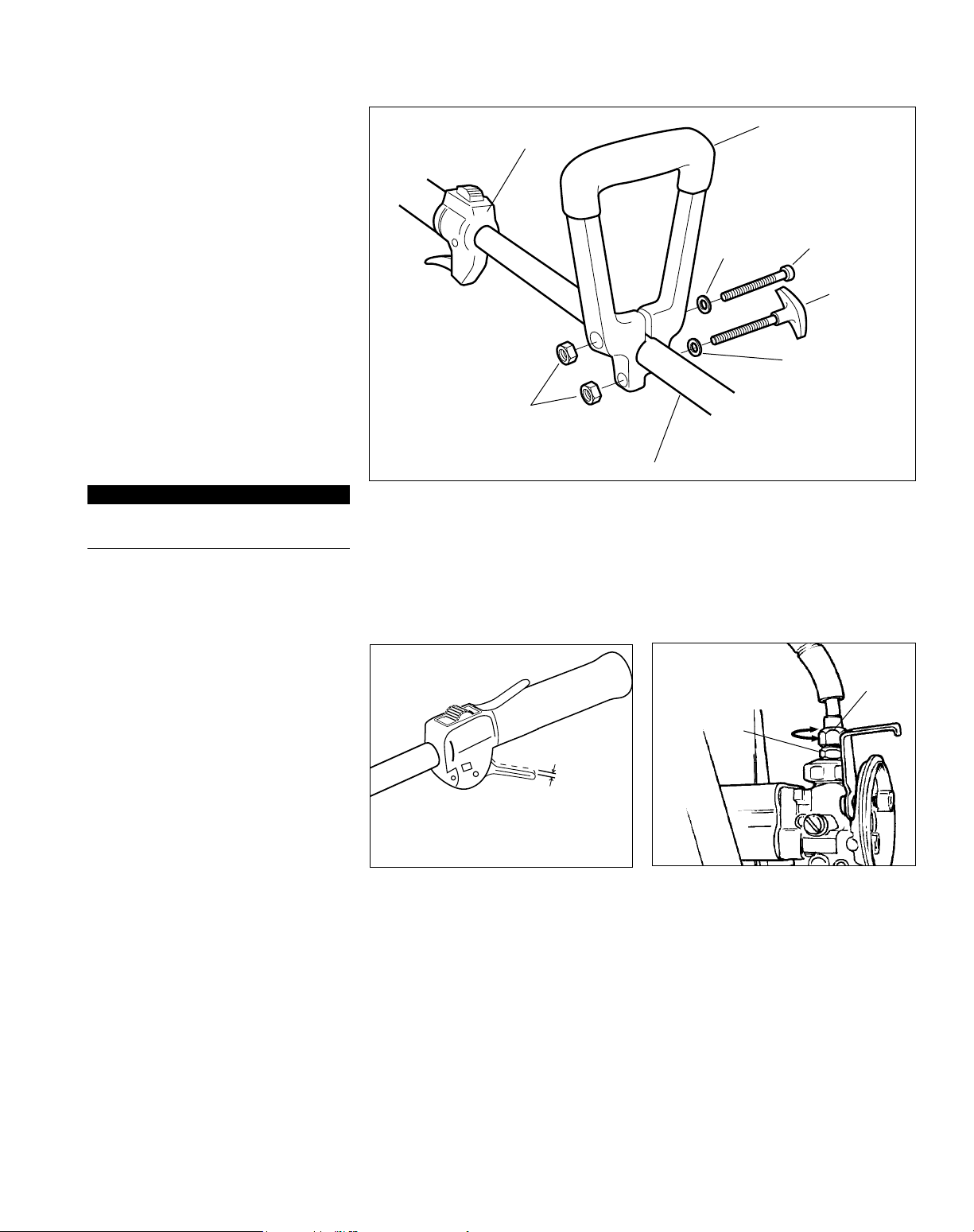
Adjustable Handle Installation
Follow these instructions if you wish to
use the PowerBroom’s adjustable handle
instead of the loop handle on youlr powerhead assembly. Remove the powerhead
assembly’s loop handle.
Remove both screws from the 1.
PowerBroom’s adjustable handle
assembly.
While spreading the handle at the 2.
mounting hole, position the handle
on the outer tube as shown.
Reinstall the two mounting screws in 3.
the handle, but do not tighten them
at this time.
Locate the handle at the best posi-4.
tion for operator comfort (usually
about 10 inches ahead of the throttle
lever), and secure it by tightening
the adjustment knob at the handle
base.
IMPORTANT!
One side of the handle is recessed to
receive the two hex nuts.
Throttle Assembly
Hex Nut
Install the adjustable handle
Handle
Mounting Screw
Washer
Adjustment Knob
Washer
Outer Tube
Throttle lever free play
Test the throttle lever for smooth 1.
operation. If any stiffness or binding
are noted, repeat Steps 1 through 4
(on the previous page).
Test the throttle lever for proper 2.
“free play” of approximately 7mm
in the idle position. If necessary,
adjustments can be made at the carburetor by loosening the cable locknut and then raising or lowering the
cable adjuster as required.
Adjust throttle lever free play
3/16-1/4 inch (4-6 mm)
Throttle Free Play
Raise or lower cable
adjuster as required
and then tighten
locknut
Locknut
Cable
Adjuster
7
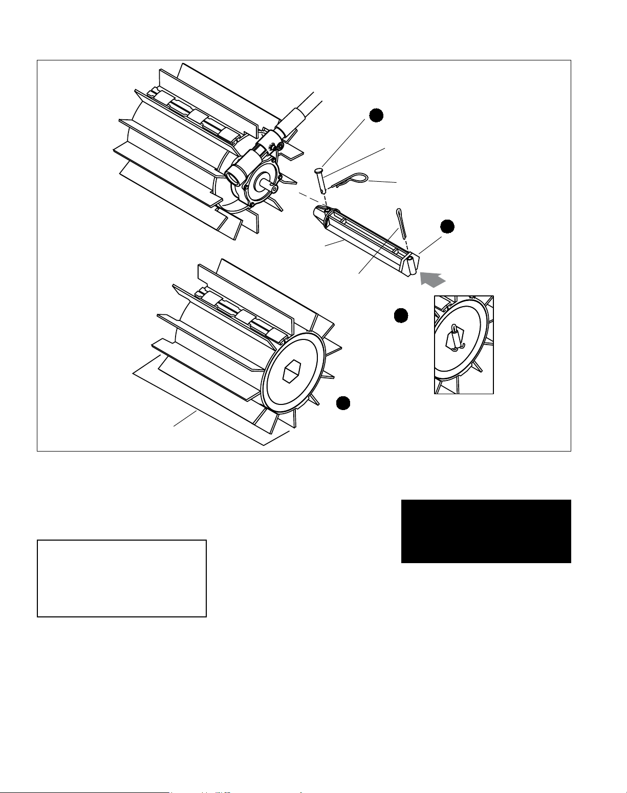
Assembly (continued)
Sweeper Assembly
Drum
Axle
Cotter
Pin
Secure the drum
2
axle to the shaft
Clevis
Pin
Hitch
Pin
3
Secure with a
cotter pin
1
Install drum
axle onto
output shaft
Drum
Assembly
Push one of the drum axles onto 1.
either of the two gearcase output
shafts. If necessary, rotate the drum
axle until the clevis pin hole in the
axle aligns with the matching hole in
the gearcase output shaft.
CAUTION!
The two drum assemblies are
identical, but each drum must be
installed with its recessed end
facing toward the gearcase.
Install the sweeper drum
4
assembly
Use a clevis pin and hitch pin to 2.
secure the drum axle to the shaft.
Slide the recessed end of a sweeper 3.
drum assembly over the installed
axle, and then push the drum down
the axle until the cotter pin hole in
the axle extends above the drum
surface.
Use a cotter pin to secure the drum 4.
assembly on the axle (see inset).
The cotter pin is designed to fit
tightly against the outboard end of
the drum, so you may need to compress the drum face slightly during
installation. spead the ends of the
cotter pin to secure.
Repeat Steps 1-4 to install the remain-5.
ing axle and drum assembly.
The PowerBroom tool should
now be completely assembled.
8
Mixing Fuel
WARNING!
Alternative fuels, such as E15 (15% ethanol), E-85 (85% ethanol) or any fuels not meeting Shindaiwa
requirements are NOT approved for use in Shindaiwa gasoline engines. Use of alternative fuels may cause
performance problems, loss of power, overheating, fuel vapor lock, and unintended machine operation, including,
but not limited to, improper clutch engagement. Alternative fuels may also cause premature deterioration of fuel
lines, gaskets, carburetors and other engine components.
Fuel Requirements
Gasoline - Use 89 Octane [R+M/2] (mid grade or higher) gasoline known to be good quality. Gasoline may contain
up to 10% Ethanol (grain alcohol) or 15% MTBE (methyl tertiary-butyl ether). Gasoline containing methanol (wood
alcohol) is NOT approved.
Hybrid 4TM Mixture Oil - Engine oil meeting ISO-L-EGD (ISO/CD 13738) and J.A.S.O. M345/FD standards must be
used. Shindaiwa highly recommends using Shindaiwa Red ArmorTM engine oil in all Shindaiwa Hybrid 4TM engines to
protect the engine from harmful carbon build up, maintain engine performance, and increase engine life. Shindaiwa
Red ArmorTM engine oil exceeds ISO-L-EGD and J.A.S.O. M345/FD performance requirements. Engine problems
due to inadequate lubrication caused by failure to use an ISO-L-EGD (ISO/CD 13738) and J.A.S.O. M345/FD certied
oil will void the engine warranty.
IMPORTANT!
Shindaiwa Red Armor
in all Shindaiwa engines sold in the past, regardless of ratio specied in those
manuals.
Stored fuel ages. Do not mix more fuel than you expect to use in thirty (30)
days, ninety (90) days when a fuel stabilizer is added. Use of unmixed, improperly mixed, or stale fuel, may cause hard starting, poor performance, or severe
engine damage and void the product warranty. Read and follow instructions in
the Long Term Storage section of this manual.
TM
engine oil may be mixed at 50:1 ratio for application
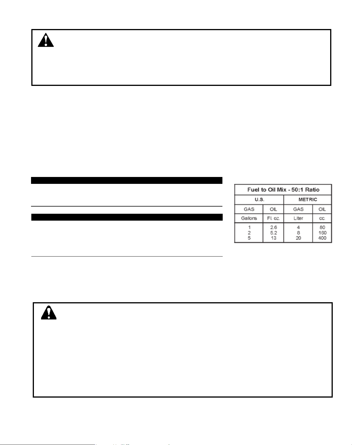
IMPORTANT!
Examples of 50:1 mixing quantities
Handling Fuel
DANGER
Fuel is VERY ammable. Use extreme care when mixing, storing or handling or serious personal injury
may result.
• Use an approved fuel container.
• DO NOT smoke near fuel.
• DO NOT allow ames or sparks near fuel.
• Fuel tanks/cans may be under pressure. Always loosen fuel caps slowly allowing pressure to equalize.
• NEVER refuel a unit when the engine is HOT or RUNNING!
• DO NOT ll fuel tanks indoors. ALWAYS ll fuel tanks outdoors over bare ground.
• DO NOT overll fuel tank. Wipe up spills immediately.
• Securely tighten fuel tank cap and close fuel container after refueling.
• Inspect for fuel leakage. If fuel leakage is found, do not start or operate unit until leakage is repaired.
• Move at least 3m (10 ft.) from refueling location before starting the engine.
9
 Loading...