

Shindaiwa M242S Owner's/operator's Manual

M242
English ..............1
Français ...... FR_1
Italiano ......... IT_1
SHINDAIWA OWNER’S/OPERATOR’S MANUAL
M242S MULTIPURPOSE
TOOL CARRIER
Part Number 65041-94310 Rev 03/2009
WARNING!
Read this manual and the manuals provided with the Shindaiwa ■
Splitboom Attachment series and familiarize yourself with its contents.
Minimize the risk of injury to yourself and others.
■
Always wear eye and hearing protection when operating this machine. ■
Do not operate or service this machine unless you clearly understand ■
this manual.
This machine is designed for cutting grass, weeds, and brush. Use
■
only for designated purpose.
Keep this manual available at all times so that you can reference it ■
whenever you have a question about the use of this unit.
2
Introduction
The Shindaiwa 242 series of hand-held
power equipment is designed and built
to deliver superior per
formance and
reliability without compromise to quality,
comfort, safety or durability.
Shindaiwa engines represent the leading
edge of high-performance engine
technology, delivering exceptionally high
power with remarkably low displacement
and weight. As an owner/operator, you’ll
soon discover for yourself why Shindaiwa
is simply in a class by itself!
Throughout this manual are special “attention statements”.
Attention Statements
WARNING!
A statement preceded by the
triangular attention symbol and the
word “WARNING” contains information
that should be acted upon to prevent
serious bodily injury.
CAUTION!
A statement preceded by the word
“CAUTION” contains information
that should be acted upon to prevent
mechanical damage.
IMPORTANT!
A statement preceded by the word
“IMPOR
TANT” is one that possesses spe-
cial significance.
NOTE:
A statement preceded by the word “NOTE”
contains information that is handy to know
and may make your job easier.
DANGER!
A statement preceded by the
triangular attention symbol and the
word “DANGER” contains information
that should be acted upon to prevent
serious injury or death.
IMPORTANT!
The operational procedures described in this manual are intended to help you get the most from this unit as well as to protect you and
others from harm. These procedures are guidelines for safe operation under most conditions, and are not intended to replace any safety
rules and/or laws that may be in force in your area. If you have questions regarding your Shindaiwa hand held power equipment, or if
you do not understand something in this manual, contact Shindaiwa Inc. at the address printed on the back of this Manual.
Shindaiwa Inc. reserves the right to make
changes to products without prior notice,
and without obligation to make alterations
to units previously manufactured.
IMPORTANT!
The information contained in these instructions describes units available at the time
of publication.
Operational and warning labels
Contents
PAGE PAGEPAGE
WARNING!
The engine exhaust from this
product contains chemicals known to
to cause cancer, birth defects or other
reproductive harm.
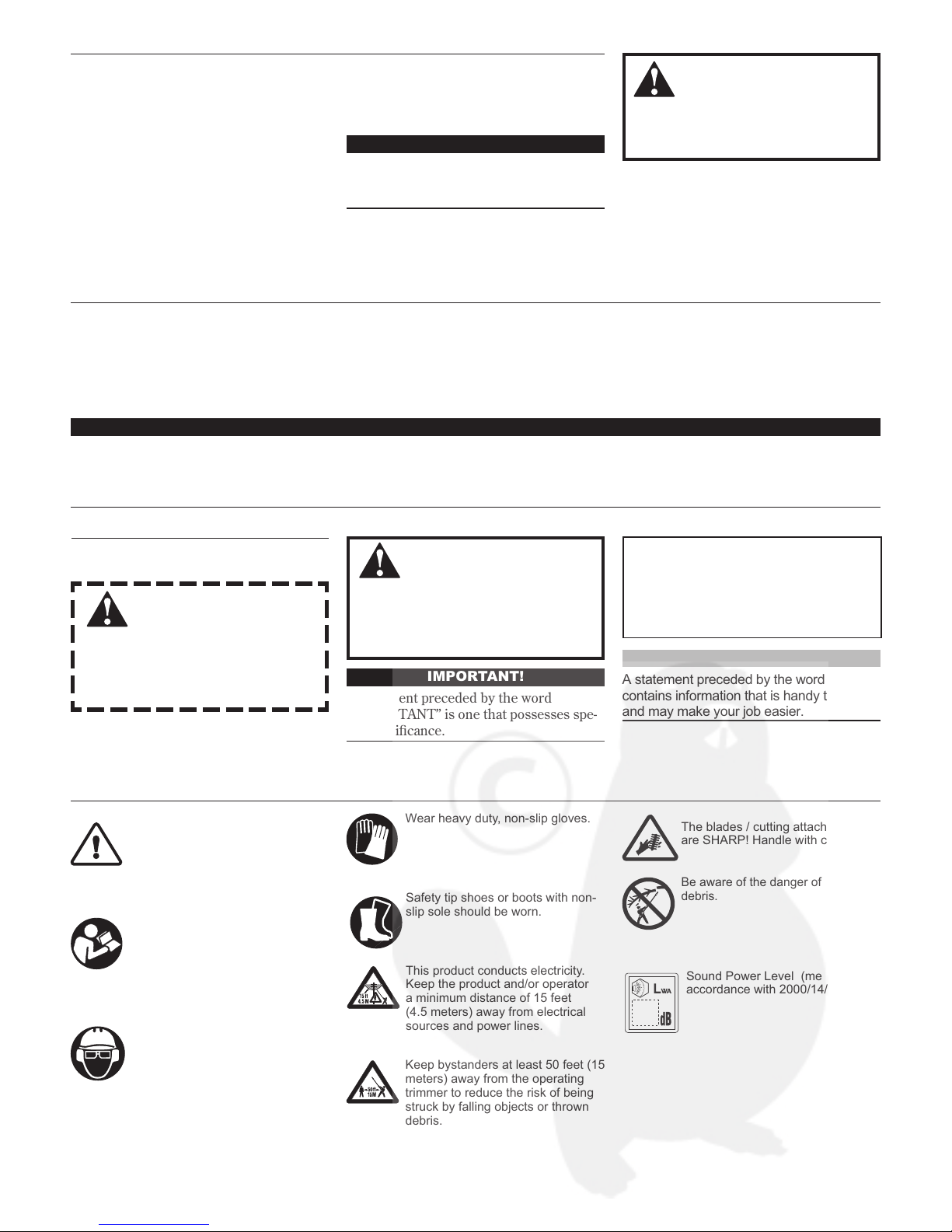
Be aware of the danger of falling
debris.
Read and follow this manual, make
sure anyone using the trimmer does
likewise. Failure to do so could
result in serious personal injury or
machine failure. Keep this manual
for future reference.
Attachments for this unit operate
at very high speeds and can do
serious damage or injury if they are
misused or abused. Never allow a
person without training or instruction
to operate this unit!
Always wear a hard hat to reduce
the risk of head injuries during
operation of this machine. In addition, always wear eye and hearing
protection. Shindaiwa recommends
wearing a face shield as additional
face and eye protection.
Wear heavy duty, non-slip gloves.
Safety tip shoes or boots with non-
slip sole should be worn.
This product conducts electricity.
Keep the product and/or operator
a minimum distance of 15 feet
(4.5 meters) away from electrical
sources and power lines.
Keep bystanders at least 50 feet (15
meters) away from the operating
trimmer to reduce the risk of being
struck by falling objects or thrown
debris.
The blades / cutting attachments
are SHARP! Handle with care.
Safety ........................................................... 3
Product Description ...................................4
Specifications ..............................................5
Assembly and adjustments .......................6
Mixing fuel ..................................................8
Filling the fuel tank .................................... 8
Starting the Engine ................................... 9
Stopping the Engine ................................10
Adjusting Engine Idle .............................. 10
Checking Unit Condition.........................10
Operation ..................................................11
Maintenance .............................................12
Long Term Storage .................................. 14
Troubleshooting Guide ...........................15
Declaration of Conformity .......................18
Sound Power Level (measured in
accordance with 2000/14/EC)
3
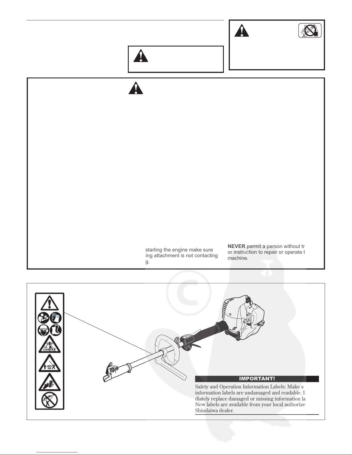
IMPORTANT!
Safety and Operation Information Labels: Make sure all
infor
mation labels are undamaged and readable. Immediately replace damaged or missing information labels.
New labels are available from your local authorized
Shindaiwa dealer.
ALWAYS wear eye protection to shield
against thrown objects.
ALWAYS wear hearing protection devices
when operating this unit. Prolonged exposure to excessive noise is fatiguing and
could lead to impaired hearing. The use
of proper ear protection can reduce this
potential hazard
NEVER operate the engine when transporting the unit. Make sure cutter safety guards
are in place when transporting this unit.
NEVER operate the engine indoors!
Make sure there is always good ventilation. Fumes from engine exhaust can
cause serious injury or death.
ALWAYS make sure there are no missing or loose fasteners and that the stop
switch and throttle controls are working
properly.
ALWAYS use the proper cutting tool for
the job.
ALWAYS clear your work area of trash or
hidden debris that could be thrown back
at you or toward a bystander.
ALWAYS make sure the cutting attach-
ment tool is properly installed and firmly
tightened before operation.
NEVER use a cracked or warped cutting
attachment: replace it with a serviceable
one and make sure it fits properly.
ALWAYS stop the engine immediately
if it suddenly begins to vibrate or shake.
Inspect for broken, missing or improperly
installed parts or attachments.
ALWAYS keep the unit as clean as practical. Keep it free of loose vegetation,
mud, etc.
NEVER extend trimming line beyond the
length specified for your unit.
ALWAYS hold the unit firmly with both
hands when cutting or trimming, and
maintain control at all times.
ALWAYS keep the handles clean.
ALWAYS disconnect the spark plug wire
before performing any maintenance work.
Before starting the engine make sure
the cutting attachment is not contacting
anything.
ALWAYS stop the engine immediately
and check for damage if you strike a
foreign object or if the unit becomes tangled. Do not operate with broken or damaged equipment.
ALWAYS maintain the Multipurpose
Engine according to this owner’s manual
and follow the recommended scheduled
maintenance.
NEVER allow the engine to run at high
RPM without a load. Doing so could
damage the engine.
ALWAYS use genuine Shindaiwa parts
and accessories when repairing or maintaining this unit.
NEVER modify or disable any of the
unit’s devices. Use only Shindaiwa genuine parts for repairs and maintenance.
WHEN transporting the unit in a vehicle,
tie it down securely to prevent damage
and fuel spillage.
NEVER permit a person without training
or instruction to repair or operate this
machine.
Work Safely
Attachments for this unit operate at very
high speeds and can do serious damage or
injury if they are misused or abused. Never
allow a person without training or instruction to operate this unit!
Stay Alert
You must be physically and mentally fit to
operate this unit safely.
Safety
WARNING!
Never make unauthorized
attachment installations.
WARNING!
Never operate power
equipment of any kind if you
are tired or if you are under the influence of alcohol, drugs, medication or
any other substance that could affect
your ability or judgement.
WARNING!
Use Good Judgment
Safety Labels
Product Description
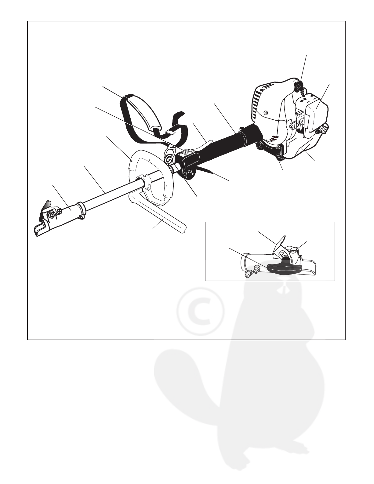
M242 Multipurpose Tool Carrier
Outer Tube
Grip
Handle
Throttle Trigger
Hangar
Barrier bar
Throttle
Interlock
Ignition Switch
Strap
Coupler Screw Knob
Latch
Latch protector
Coupler
Spark Plug
Air cleaner
Fuel tank
Tank guard
Using the accompanying illustration as a
guide, familiarize yourself with this unit and
its various components. Understanding your
unit helps ensure top performance, long
service life and safer operation.
4

Specifications are subject to change without notice. *Shindaiwa One engine oil meets or exceeds these specifications and is recommended for all Shindaiwa products.
Specifications
Engine Name M242/EC2
Engine model SF242EC2
Engine type 2-cycle catalyst
Dry weight (less attachments) 4.5 kg
Dimensions (L xHxW)
1038 mm x 213 mm x 250 mm
Displacement 23.9 cc
Bore x stroke 34 x 27 mm
Engine Speed at Maximum Power Output min
-1
Maximum power output 0.8 kW @ 8000 min
-1
(rpm)
Engine speed at idling min
-1
Maximum engine speed min
-1
Fuel tank capacity 620 cm
3
Fuel/oil ratio 50:1 with ISO-L-EGD or JASO FC class 2-cycle mixing oil*
Carburetor Walbro WYK diaphragm-type
Ignition One-piece electronic transistor-controlled
Spark plug NGK BPMR6A
Spark plug torque value 17–19 N·m
Air filter Non-reversible foam filter element
Starting method Recoil
Stopping method Slide switch
Cooling system Forced air
Transmission type
Automatic, centrifugal clutch with bevel gear
Specifications are subject to change without notice.
*Sound Pressure Level: In accordance with EN ISO 11806 and ISO
22868 (average data between Idling and a WOT)
**Sound Power Level: In accordance with EN ISO 11806 and ISO
22868 (average data between at Idling and at WOT)
***Vibration Level: In accordance with EN ISO 11806 and ISO
22867.
Note 1: 8-tooth blade equipped
Note 2: Trimmer head equipped
Sound Pressure Level * (average data between at Idling and at WOT) Note 1 dB (A)
Sound Power Level ** (average data between at Idling and at WOT) Note 1 dB (A)
Vibration Level** (Idling [Front/Rear]) Note 1 / m/s
2
(WOT [Front/Rear]) / m/s
2
Sound Pressure Level * (average data between at Idling and at WOT) Note 2 dB (A)
Sound Power Level ** (average data between at Idling and at WOT) Note 2 dB (A)
Vibration Level*** (Idling [Front/Rear]) Note 2 / m/s
2
(WOT [Front/Rear]) Note 2 / m/s
2
With Shindaiwa SBA-TX24 Splitboom Attachment
Specifications are subject to change without notice.
*Sound Pressure Level: In accordance with ISO 11680-1
**Sound Power Level: In accordance with ISO 11680-1
***Vibration Level: In accordance with ISO11680-1
Sound Pressure Level * (Idling) dB (A)
(WOT) dB (A)
Sound Power Level ** (Idling) dB (A)
(WOT) dB (A)
Vibration Level*** (Idling [Front/Rear]) / m/s
2
(WOT [Front/Rear]) / m/s
2
With Shindaiwa SBA-P24 Splitboom Attachment (254 mm Guide Bar Equipped)
Specifications are subject to change without notice.
*Sound Pressure Level: In accordance with ISO 11680-1
**Sound Power Level: In accordance with ISO 11680-1
***Vibration Level: In accordance with ISO11680-1
Sound Pressure Level * (Idling) dB (A)
(WOT) dB (A)
Sound Power Level ** (Idling) dB (A)
(WOT) dB (A)
Vibrati Level*** (Idling [Front/Rear]) / m/s
2
(WOT [Front/Rear]) / m/s
2
With Shindaiwa SBA-AH2422 Splitboom Attachment
5
6
Assembly and adjustments
Prior to assembly
This Shindaiwa Multipurpose Tool Carrier
comes fully assembled. You only need
attach the accessory tool of your choice to
the powerhead.
Your Multipurpose tool carrier includes:
Shoulder strap
■
IMPORTANT!
The terms “left”, “left-hand”, and “LH”;
“right”, “right-hand”, and “RH”; “front” and
“rear” refer to directions as viewed by the
operator during normal operation.
WARNING!
Do not make unauthorized
modifications or alterations to any of
these units or their components.
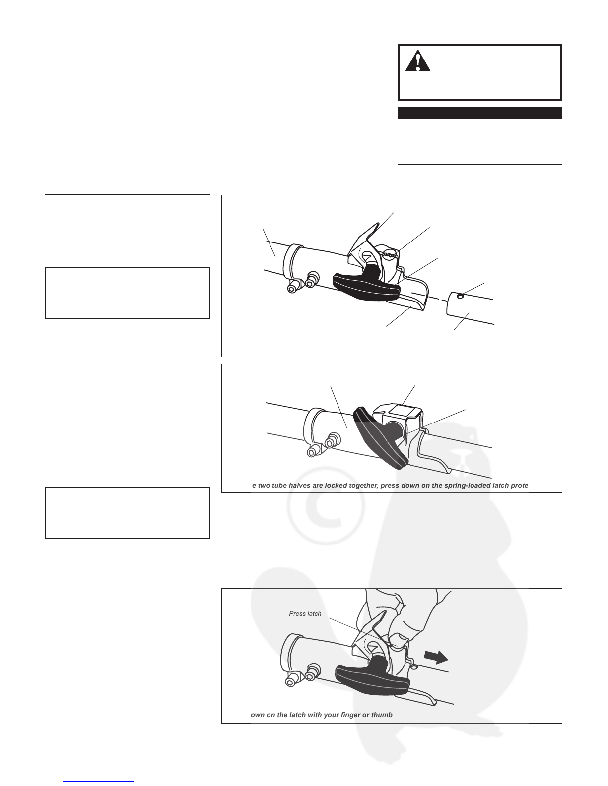
When the two tube halves are locked together, press down on the spring-loaded latch protector
Press latch
With the unit on a clean, flat surface, 1.
loosen the coupler screw. The springloaded coupler protector should pop up.
Press down on the latch with your finger 2.
or thumb. This releases the coupler lock.
Pull the upper tube assembly out of the 3.
coupler.
Disassembling the tube sections
Tool assembly
Lower tube assembly
Coupler
Latch
Coupler screw
knob
Locking hole
Latch protector (extended)
Slip off the protective plastic cover(s) 2.
from the ends of the tube(s), and
loosen the coupler screw knob.
Insert the tool assembly into the cou-3.
pler, with the tool decal facing up, until
the line of the decal is flush with the
end of the coupler.
Twist the tool assembly back and forth 4.
until you are sure it snaps in place by
the coupler latch.
When the two tube halves are locked 5.
together, press down on the springloaded latch protector and tighten the
coupler screw knob.
Latch Protector (lowered)
Coupler Screw Knob
Coupler
Assembling tube sections
Place powerhead/lower tube assembly 1.
on a clean, flat surface so that both
assemblies fit end to end. The powerhead/lower tube assembly should be
facing positioned with the locking hole
in the tube end facing up.
CAUTION!
Keep the open ends of the tubes clean
and free of debris!
Insert the tool assembly into the coupler
Press down on the latch with your finger or thumb
Kit containing this owner’s/operator’s ■
manual and tool kit for routine mainten
ance. Tool kits vary by model and may
include a hex wrench, and a spark plug/
screwdriver combination wrench.
CAUTION!
Verify that there is no gap between the
latch protector and coupler.
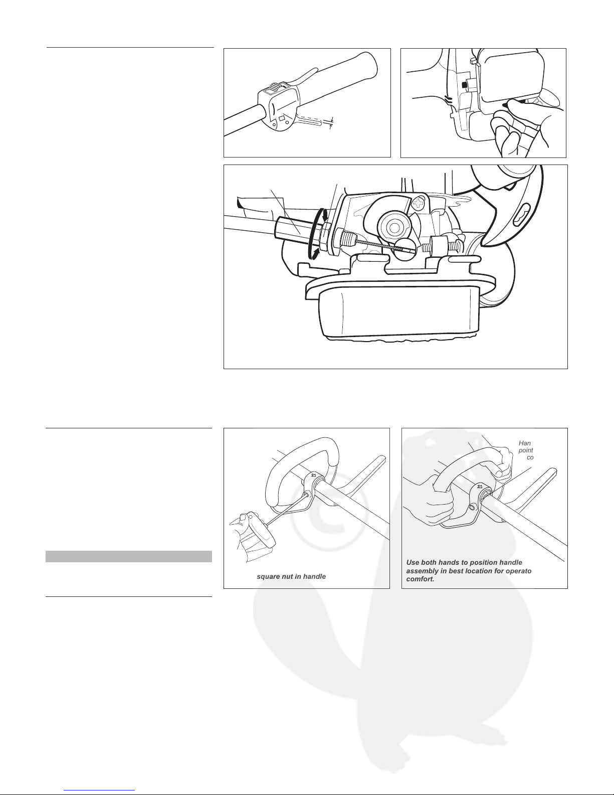
4 - 6 mm
Remove air cleaner cover
Throttle lever free play
Lock Nut
Cable
Adjuster
Adjust as required to obtain 4-6 mm free play
7
Assembly and adjustments (continued)
Throttle lever free play
The thro
ttle lever free play should be
approximately 4 - 6 mm. Make sure that
the throttle lever operates smoothly
without binding. If it becomes necessary to
adjust the lever free play, follow the procedures and illustrations that follow.
Loosen the air cleaner cover knobs and 1.
remove the air cleaner cover.
Loosen the lock nut on the cable 2.
adjuster.
Turn the cable adjuster in or out as 3.
required to obtain proper free play 4-6
mm (3/16-1/4 inch).
Tighten the locknut.4.
Reinstall the air cleaner cover.5.
Adjusting the handle
Use both hands to position handle
assembly in best location for operator
comfort.
Handle arrow
points toward
coupler
.
Loosen square nut in handle
Your Shindaiwa Multi-Purpose Tool Carrier comes with the handle installed. It can
be re-adjusted for operator comfort in the
following manner.
Place the unit on a clean, flat surface.1.
With a hex wrench, loosen the square 2.
nut as shown.
Slide handle assembly to desired 3.
position.
NOTE
Moving the handle may require two hands
and rocking motions, as the handle and
clamp fit tightly to the outer tube.
8
CAUTION
Never use any type of gasoline containing more than 10% alcohol by volume!
Some types of gasoline contain alcohol
as an oxygenate. Oxygenated gasoline may cause increased operating
temperatures. Under certain conditions, alcohol-based gasoline may also
reduce the lubricating qualities of some
2-cycle mixing oils.
Generic oils and some outboard
oils may not be intended for use in
high-performance 2-cycle engines,
and should never be used in your
Shindaiwa engine.
Mixing fuel
Filling the fuel tank
CAUTION
This engine is designed to operate on
a 50:1 mixture consisting of unleaded
gasoline and ISO-L-EGD or JASO FD
class 2-cycle mixing oil only
. Use of
non-approved mixing oils can lead to
excessive carbon deposits.
Use only fresh, clean unleaded gasoline ■
with a pump octane of 87 or higher.
Mix all fuel with a 2-cycle air-cooled
■
mixing oil that meets or exceeds ISO-LEGD and/or JASO FD classified oils at
50:1 gasoline/oil ratio.
Examples of 50:1 mixing quantities
WARNING!
Minimize the Risk of Fire
Gasoline 2-cycle mixing oil
liters milliliters
2.5 - L
50 mL
5 - L 100 mL
10 - L 200 mL
20 - L 400 mL
IMPORTANT!
Mix only enough fuel for your immediate
needs! If fuel must be stored longer than 30
days and oil with fuel stabilizer is not
used, it should first be treated with a fuel
stabilizer such as STA-BIL™.
Oil is a registered JASO FD classi-
fied oil and also meets or exceeds ISO-L-EGD
performance requirements. Shindaiwa One is
recommended for use in all Shindaiwa low emissions engines. Shindaiwa One also includes a
fuel stabilizer.
NEVER ■ smoke or light fires near the
engine.
ALWAYS ■ stop the engine and allow
it to cool before refueling.
ALWAYS ■ Wipe all spilled fuel and
move at least 3 meters (10 feet)
from the fueling point and source
before starting.
NEVER ■ place flammable material
close to the engine muffler
.
NEVER ■ operate the engine with-
out the muffler and spark arrester
screen in place and in good working condition.
FUEL IS HIGHLY FLAMMABLE. ■
ALWAYS ■ store gasoline in a con-
tainer approved for flammable
liquids.
ALWAYS ■ inspect the unit for fuel
leaks before each use. During each
refill, check that no fuel leaks from
around the fuel cap and/or fuel tank.
If fuel leaks are evident, stop using
the unit immediately. Fuel leaks must
be repaired before using the unit.
ALWAYS ■ move the unit at least 3
meters (10 feet) away from a fuel
storage area or other readily flam-
mable materials before starting
the engine.
Place the unit on a flat, level surface.1.
Clear any dirt or other debris from 2.
around the fuel filler cap.
Remove the fuel cap, and fill the tank 3.
with clean, fresh fuel.
Reinstall the fuel filler cap and tighten 4.
firmly.
Wipe away any spilled fuel before start-5.
ing engine.
CAUTION!
Slowly remove the fuel cap only after
stopping the engine
CAUTION!
Mix and pour fuel outdoors where there
are no sparks and flames.
 Loading...