

Shindaiwa M242 Owner's/operator's Manual
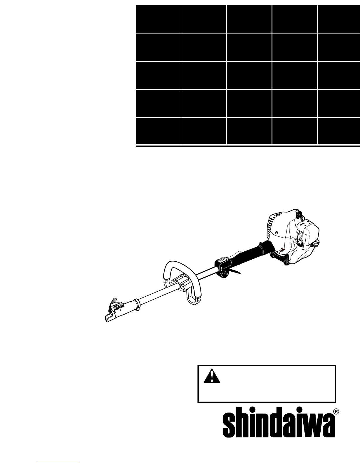
SHINDAIWA OWNER’S/OPERATOR’S MANUAL
M242
MULTIPURPOSE
TOOL CARRIER
WARNING!
Always wear eye protection when operating
this machine. To minimize the risk of injury, read this
manual and familiarize yourself with its contents.
X7502802102
02/13
2
Introduction
Throughout this manual are special “attention statements”.
Attention Statements
WARNING!
A statement preceded by the
triangular attention symbol and the
word “WARNING” contains information that should be acted upon to
prevent serious bodily injury.
CAUTION!
A statement preceded by the word
“CAUTION” contains information
that should be acted upon to prevent mechanical damage.
IMPORTANT!
A statement preceded by the word
“IMPORTANT” is one that possesses
special signicance.
NOTE:
A statement preceded by the word “NOTE”
contains information that is handy to know
and may make your job easier.
DANGER!
A statement preceded by
the triangular attention symbol and
the word “DANGER” contains information that should be acted upon
to prevent serious injury or death.
IMPORTANT!
The operational procedures described in this manual are intended to help you get the most from this unit as well as to
protect you and others from harm. These procedures are guidelines for safe operation under most conditions, and are not
intended to replace any safety rules and/or laws that may be in force in your area. If you have questions regarding your
Shindaiwa hand held power equipment, or if you do not understand something in this manual, contact Shindaiwa at the address printed on the back of this Manual.
ECHO, Inc. reserves the right to make
changes to products without prior notice,
and without obligation to make alterations to units previously manufactured.
IMPORTANT!
The information contained in these
instructions describes units available at
the time of publication.
Operational and warning labels
Contents
PAGE
PAGE
PAGE
WARNING!
The engine exhaust from
this product contains chemicals
known to to cause cancer, birth
defects or other reproductive
harm.
Safety ..................................................... 3
Product Description ............................. 4
Specifications ........................................ 5
Emission Control ................................. 5
Assembly and adjustments ................. 6
Mixing fuel ............................................ 7
Filling the fuel tank .............................. 8
Starting the Engine ............................. 9
Stopping the Engine .......................... 10
Operation ............................................ 10
Maintenance ....................................... 11
Long Term Storage ............................ 15
Troubleshooting Guide ..................... 16
Warranty Statement ........................... 19
This machine has been designed and
built to deliver superior performance
and reliability without compromise to
quality, comfort, safety or durability.
Shindaiwa engines represent the leading edge of high-performance engine
technology, delivering exceptionally high
power with remarkably low displacement and weight. As an owner/operator,
you’ll soon discover for yourself why
Shindaiwa is simply in a class by itself!
Read and follow this manual,
make sure anyone using the unit
does likewise. Failure to do so
could result in serious personal
injury or machine failure. Keep
this manual for future reference.
Always wear a hard hat to
reduce the risk of head injuries
during operation of this machine.
In addition, always wear eye and
hearing protection. Shindaiwa
recommends wearing a face
shield as additional face and eye
protection.
Wear heavy duty, non-slip
gloves.
Safety tip shoes or boots with
non-slip sole should be worn.
WARNING: Surface can
be hot. Always wear
gloves when handling
this unit.
3
Safety
Work Safely
Attachments for this unit operate at very
high speeds and can do serious damage
or injury if they are misused or abused.
Never allow a person without training or
instruction to operate this unit!
Stay Alert
You must be physically and mentally fit
to operate this unit safely.
WARNING!
Never make unauthorized
attachment installations.
WARNING!
Never operate
power equipment of any
kind if you are tired or if you are
under the inuence of alcohol,
drugs, medication or any other substance that could affect your ability
or judgement.
WARNING!
Use Good Judgment
ALWAYS wear eye protection to shield
against thrown objects.
ALWAYS wear hearing protection
devices when operating this unit.
Prolonged exposure to excessive noise
is fatiguing and could lead to impaired
hearing. The use of proper ear protection can reduce this potential hazard
NEVER operate the engine when transporting the unit. Make sure cutter safety
guards are in place when transporting this
unit.
NEVER operate the engine indoors!
Make sure there is always good ventilation. Fumes from engine exhaust can
cause serious injury or death.
ALWAYS make sure there are no missing or loose fasteners and that the stop
switch and throttle controls are working
properly.
ALWAYS use the proper cutting tool for
the job.
ALWAYS clear your work area of trash
or hidden debris that could be thrown
back at you or toward a bystander.
ALWAYS make sure the cutting attach-
ment tool is properly installed and rmly
tightened before operation.
NEVER use a cracked or warped
cutting attachment: replace it with a
serviceable one and make sure it ts
properly.
ALWAYS stop the engine immediately
if it suddenly begins to vibrate or shake.
Inspect for broken, missing or improperly installed parts or attachments.
ALWAYS keep the unit as clean as
practical. Keep it free of loose vegetation, mud, etc.
ALWAYS hold the unit rmly with both
hands when cutting or trimming, and
maintain control at all times.
ALWAYS keep the handles clean.
ALWAYS disconnect the spark plug wire
before performing any maintenance
work.
Before starting the engine make sure
the cutting attachment is not contacting
anything.
ALWAYS stop the engine immediately and check for damage if you
strike a foreign object or if the unit
becomes tangled. Do not operate
with broken or damaged equipment.
ALWAYS maintain the Multipurpose
Engine according to this owner’s
manual and follow the recommended
scheduled maintenance.
NEVER allow the engine to run at
high RPM without a load. Doing so
could damage the engine.
ALWAYS use genuine Shindaiwa
parts and accessories when repairing
or maintaining this unit.
NEVER modify or disable any of the
unit’s devices. Use only Shindaiwa
genuine parts for repairs and maintenance.
WHEN transporting the unit in a vehicle, tie it down securely to prevent
damage and fuel spillage.
NEVER permit a person without
training or instruction to repair or
operate this machine.
Be aware of the danger of falling
debris.
This product conducts electricity.
Keep the product and/or operator
a minimum distance of 15 feet
(4.5 meters) away from electrical
sources and power lines.
Keep bystanders at least 50
feet (15 meters) away from the
operating unit to reduce the risk
of being struck by falling objects
or thrown debris.
The blades / cutting attachments
are SHARP! Handle with care.
WARNING!
The ignition components of this machine generate an electromagnetic eld during operation which may interfere
with some pacemakers. To reduce the risk of serious or fatal injury, persons with pacemakers should consult with their
physician and the pacemaker manufacturer before operating this machine. In the absence of such information, ECHO
does not recommend the use of ECHO products by anyone who has a pacemaker.
4
WARNING!
Do not make unauthorized modications or alterations to any of these
units or their components.
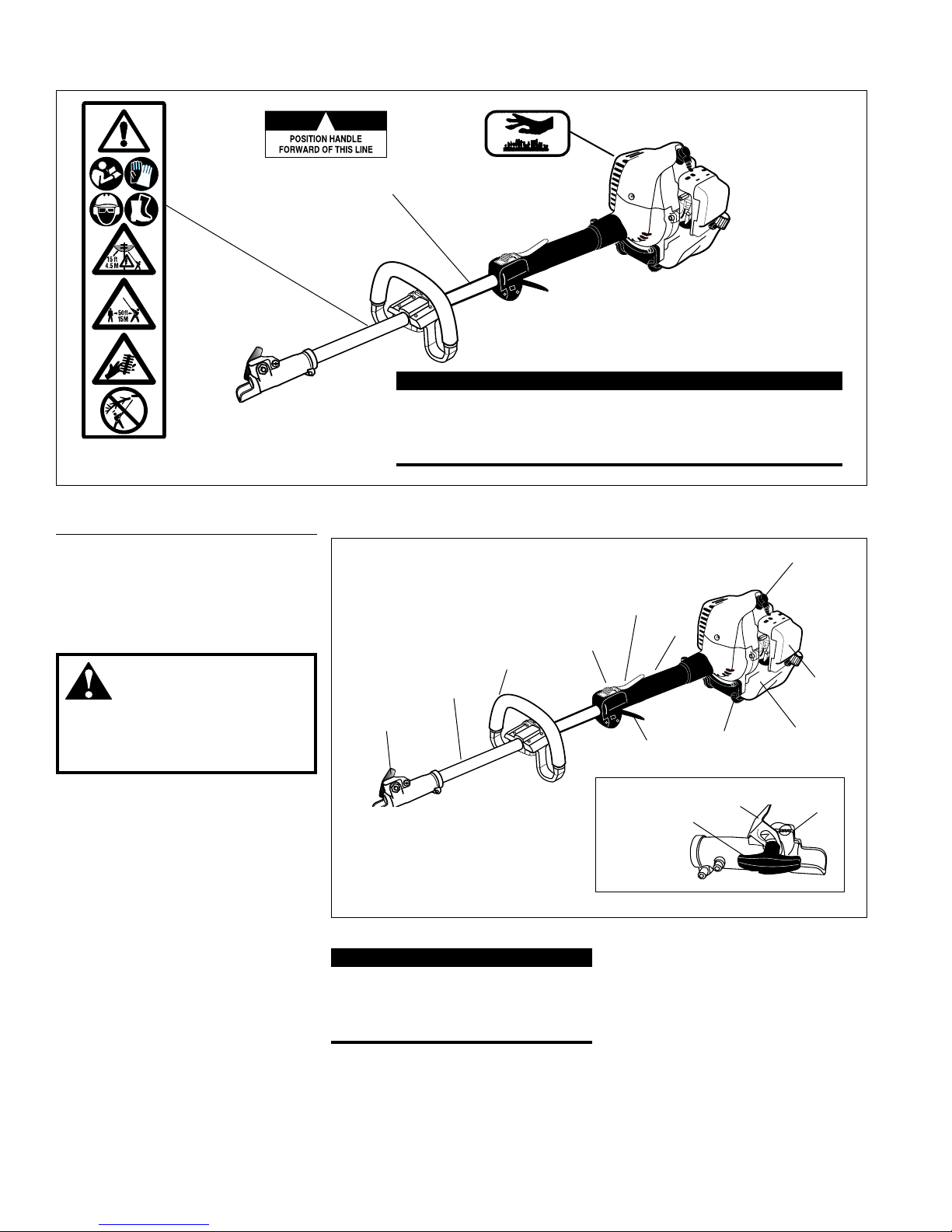
Safety Labels
Figure 1
Product Description
M242 Multipurpose
Tool Carrier
Outer Tube
Fuel Tank
Grip
Using the accompanying illustrations
as a guide, familiarize yourself with
your unit and its various components.
Understanding your unit helps ensure
top performance, long service life, and
safer operation. See Figure 2 and 2a.
Handle
Coupler
Throttle
Trigger
Throttle Lockout
Lever
Tank Guard
Figure 2
Ignition
Switch
Air Cleaner
Spark Plug
M23002a
Coupler Screw Knob
Latch
Latch protector
Figure 2a
Prior to Assembly
Before assembling, make sure you have
all the components required for a complete unit:
■ Engine/Outer tube assembly
■ Handle
■ Assembly Tool (s)
■ Operator’s Manual
■ Emission Control Warranty
Statement
■ Safety Glasses
Carefully inspect all components for
damage.
IMPORTANT!
The terms “left”, “left-hand”, and “LH”;
“right”, “right-hand”, and “RH”; “front”
and “rear” refer to directions as viewed
by the operator during normal operation.
IMPORTANT!
Safety and Operation Information Labels: Make sure all information
labels are undamaged and readable. Immediately replace damaged
or missing information labels. New labels are available from your
local authorized Shindaiwa dealer.
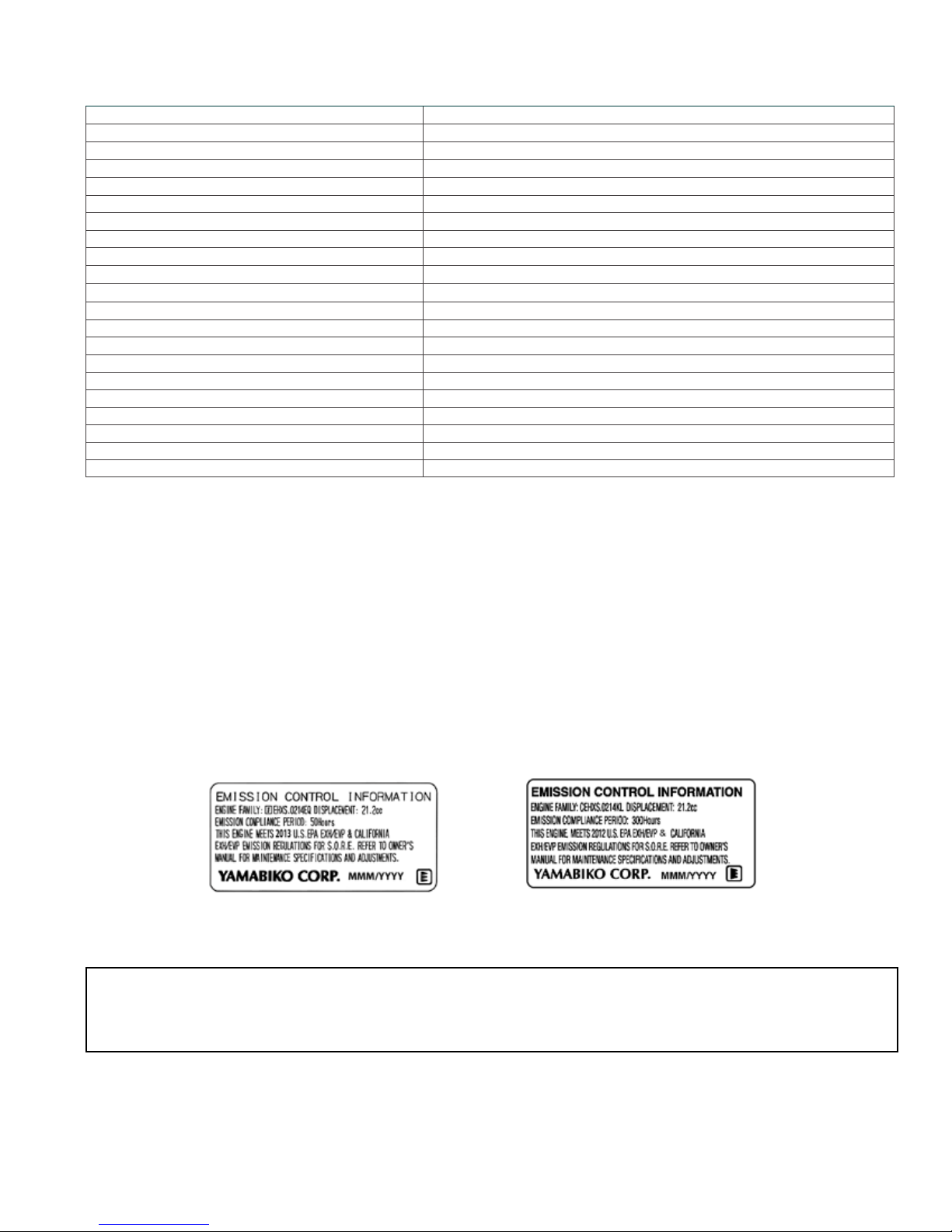
This label indicates the minimum distance between
front handle and rear grip per ANSI B175.3.
5
Specications
Specifications are subject to change without notice.
Engine Name M242
Engine Type 2-stroke, single cylinder, air cooled, gasoline engine
Dry Weight (less attachment) 4.4 kg / 9.8 lb.
Dimensions (L x H x W) mm 1034 x 245 x 248 mm / 40.7 x 9.65 x 9.76 in.
Bore x Stroke 33 x 28 mm (1.3 x 1.1 in.)
Displacement 23.9 cc (1.46 cu. in.)
Fuel/Oil Ratio 50:1 with *ISO-L-EGD or JASO FD class engine oil
Fuel Tank Capacity 690 ml (23.3 oz.)
Carburetor Type Diaphragm-type carburetor
Ignition One-piece electronic, transistor-controlled
Spark Plug** NGK BPMR8Y
Spark Plug Gap 0.6 mm (0.024 in)
Torque 16.7 - 18.6 N∙m (148-165 in • lbf)
Air Cleaner Type Non-reversible foam filter element
Starting Method Recoil Starter
Stopping Method Slide switch
Transmission Type Automatic, centrifugal clutch w/bevel gear
Engine Idle Speed 3,000 RPM
Clutch Engagement Speed 3,850 RPM
Wide Open Throttle Speed (W.O.T.) w/nylon line head 9,600 RPM
Wide Open Throttle Speed (W.O.T.) w/ blade 12,000 RPM
An Emission Control Label is located on the engine. (This is an EXAMPLE ONLY, information on label varies by engine FAMILY).
PRODUCT EMISSION DURABILITY (EMISSION COMPLIANCE PERIOD)
The 50 or 300 hour emission compliance period is the time span selected by the manufacturer certifying the
engine emissions output meets applicable emissions regulations, provided that approved maintenance procedures are followed as listed in the Maintenance Section of this manual.
Emission Control (Exhaust & Evaporative)
EPA 2010 and Later and/or C.A.R.B. TIER III
The emission control system for the engine is EM (engine modication) and, if the second to last character of the Engine Family on the Emission Control Information label (sample below) is “C”, “K”, or “T”, the emission control system
is EM and TWC (3-way catalyst). The fuel tank/fuel line emission control system is EVAP (evaporative emissions).
Evaporative emissions for California models are only applicable to fuel tanks.
6
Outer Tube
Socket-head
Capscrews
Handle
Mounting Bracket
Throttle
Assembly
Handle Assembly
M23006
M23005
M23004
Installing a Tool Attachment
1. Place the M242 Multipurpose Tool
Carrier and the Tool Assembly on
a clean, flat surface so that both assemblies fit end to end. The M242
assembly should be facing up, and the
tool assembly should be positioned
with the locking hole in the tube end
facing up. See Figure 4.
Tool Assembly
M242 Tube
Assembly
Coupler
Latch
Coupler
Screw
Knob
Locking Hole
Latch Protector
(extended)
Latch Protector
(lowered)
Coupler Screw
Knob
Coupler
Press
Latch
Figure 4
Figure 5
Figure 6
Removing a Tool Attachment
1. With the unit on a clean, flat surface,
loosen the coupler screw knob. The
spring-loaded coupler protector
should pop up.
2. Press down on the latch with your
finger or thumb. This releases the
coupler lock. See Figure 6.
3. Pull the tool assembly out of the
coupler.
CAUTION!
Keep the open ends of the tubes
clean and free of debris!
2. Slip off the protective covers from the
ends of both tubes, and loosen the
coupler screw knob.
3. Insert the upper tube assembly into
the coupler, with the tool decal facing
up, until the line of the decal is flush
with the end of the coupler. Twist the
tool back and forth until you are sure
it snaps in place by the coupler latch.
See Figure 4.
4. When the two tube halves are locked
together, press down on the springloaded latch protector and tighten the
coupler screw knob. See Figure 5.
Front handle installation
NOTE:
Label shows minimum spacing for front
handle location.
1. Position front handle for comfortable
operation and secure screws.
7
WARNING!
Alternative fuels, such as E15 (15% ethanol), E-85 (85% ethanol) or any fuels not meeting Shindaiwa
requirements are NOT approved for use in Shindaiwa gasoline engines. Use of alternative fuels may cause
performance problems, loss of power, overheating, fuel vapor lock, and unintended machine operation, including,
but not limited to, improper clutch engagement. Alternative fuels may also cause premature deterioration of fuel
lines, gaskets, carburetors and other engine components.
Fuel Requirements
Gasoline - Use 89 Octane [R+M/2] (mid grade or higher) gasoline known to be good quality. Gasoline may contain
up to 10% Ethanol (grain alcohol) or 15% MTBE (methyl tertiary-butyl ether). Gasoline containing methanol (wood
alcohol) is NOT approved.
2 Stroke Mixture Oil - A 2-stroke engine oil meeting ISO-L-EGD (ISO/CD 13738) and J.A.S.O. M345/FD standards
must be used. Shindaiwa OneTM 2-Stroke Oil is strongly recommended as it meets this standard and is specically
formulated for use in all Shindaiwa 2-stroke engines. Engine problems due to inadequate lubrication caused by fail-
ure to use an ISO-L-EGD (ISO/CD 13738) and J.A.S.O. M345/FD certied oil will void the engine warranty.
Mixing Fuel
For increased engine protection, Shindaiwa recommends using Shindaiwa Red ArmorTM engine oil to protect the
engine from harmful carbon build up, maintain engine performance, and increase engine life. Shindaiwa Red ArmorTM
engine oil exceeds ISO-L-EGD and J.A.S.O. M345/FD performance requirements.
IMPORTANT!
Shindaiwa One
TM
2-Stroke oil or Red ArmorTM engine oil may be mixed at 50:1
ratio for application in all Shindaiwa engines sold in the past, regardless of ratio
specied in those manuals.
IMPORTANT!
Stored fuel ages. Do not mix more fuel than you expect to use in thirty (30)
days, ninety (90) days when a fuel stabilizer is added. Use of unmixed, improperly mixed, or stale fuel, may cause hard starting, poor performance, or severe
engine damage and void the product warranty. Read and follow instructions in
the Long Term Storage section of this manual.
Examples of 50:1 mixing quantities
Handling Fuel
DANGER
Fuel is VERY ammable. Use extreme care when mixing, storing or handling or serious personal injury may result.
• Use an approved fuel container.
• DO NOT smoke near fuel.
• DO NOT allow ames or sparks near fuel.
• Fuel tanks/cans may be under pressure. Always loosen fuel caps slowly allowing pressure to equalize.
• NEVER refuel a unit when the engine is HOT or RUNNING!
• DO NOT ll fuel tanks indoors. ALWAYS ll fuel tanks outdoors over bare ground.
• DO NOT overll fuel tank. Wipe up spills immediately.
• Securely tighten fuel tank cap and close fuel container after refueling.
• Inspect for fuel leakage. If fuel leakage is found, do not start or operate unit until leakage is repaired.
• Move at least 3m (10 ft.) from refueling location before starting the engine.
8
After use
• DO NOT store a unit with fuel in its tank. Leaks can
occur. Return unused fuel to an approved fuel storage container.
Storage - Fuel storage laws vary by locality. Contact
your local government for the laws affecting your area.
As a precaution, store fuel in an approved, airtight
container. Store in a well-ventilated, unoccupied build-
ing, away from sparks and ames.
IMPORTANT!
Stored fuel may separate. ALWAYS shake fuel container thoroughly before each use.
Mixing Instructions
1. Fill an approved fuel container with half of the
required amount of gasoline.
2. Add the proper amount of engine oil to gasoline.
3. Close container and shake to mix oil with gasoline.
4. Add remaining gasoline, close fuel container, and
remix.
IMPORTANT!
Spilled fuel is a leading cause of hydrocarbon emissions.
Some states may require the use of automatic fuel shutoff containers to reduce fuel spillage.
Filling the fuel tank
WARNING!
Minimize the Risk of Fire
1. Place the unit on a flat, level surface.
2. Clear any dirt or other debris from around the fuel filler cap.
3. Remove the fuel cap, and fill the tank with clean, fresh fuel.
4. Reinstall the fuel filler cap and tighten firmly.
5. Wipe away any spilled fuel before starting engine.
CAUTION!
Slowly remove the fuel cap only after stopping the engine
■ NEVER smoke or light res near the engine.
■ ALWAYS stop the engine and allow it to cool before
refueling.
■ ALWAYS Wipe all spilled fuel and move at least 3
meters (10 feet) from the fueling point and source before
starting.
■ NEVER place ammable material close to the engine
mufer.
■ NEVER operate the engine without the mufer and spark
arrester screen in place and in good working condition.
■ FUEL IS HIGHLY FLAMMABLE.
■ ALWAYS store gasoline in a container approved for
ammable liquids.
■ ALWAYS inspect the unit for fuel leaks before each
use. During each rell, check that no fuel leaks from
around the fuel cap and/or fuel tank.
If fuel leaks are evident, stop using the unit immediately. Fuel leaks must be repaired before using the unit.
■ ALWAYS move the unit at least 3 meters (10 feet)
away from a fuel storage area or other readily am-
mable materials before starting
the engine.
 Loading...