

Page 1
English...............1
Spanish.......SP_1
French.........FR_1
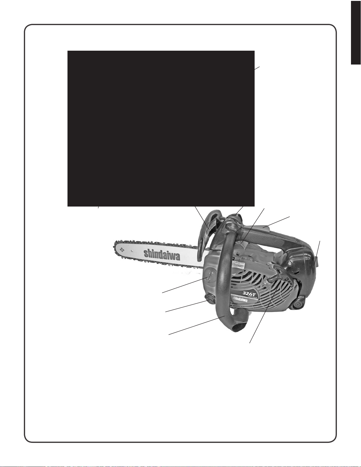
SHINDAIWA OWNER’S/OPERATOR’S MANUAL
326T CHAINSAW
WARNING!
Minimize the risk of injury to yourself and others! Read this manual
and familiarize yourself with the contents. Always wear eye and hearing protection when operating this unit.
Part Number 82085 Rev. 8/2008
Page 2

English
Ru l e s f o R sa f e op e R a t i o n
A. Kickback safety precautions for chain saw users
WARNING!
KICKBACK may occur when the nose or tip of the guide
bar touches an object, or when the wood closes in and
pinches the saw chain in the cut.
Tip contact in some cases may cause a lightning fast
reverse REACTION, Kicking the guide bar up and back
towards the operator. Pinching the saw chain along the
top of the guide bar may push the guide bar rapidly back
towards the operator. Either of these reactions may cause
you to lose control of the saw which could result in serious
personal injury.
The Kick Guard ® device is not installed on the guide bar
when you purchase your Shindaiwa chain saw. The Kick
Guard ® can be used in a majority of cutting operations,
and is especially recommended for beginners, homeowners, or chain saw novices. Most cutting operations can be
accomplished with the Kick Guard® in place.
Do not rely exclusively upon the safety devices built into
your saw. As a chain saw user, you should take several
steps to keep your cutting jobs free from accident or injury.
1.
With a basic understanding of kickback, you can
reduce or eliminate the element of surprise. Sudden
surprise contributes to accidents.
2.
Keep a good rm grip on the saw with both hands, the
right hand on the rear handle, and the left hand on the
front handle, when the engine is running. Use a rm
grip with thumbs and ngers encircling the chain saw
handles. A rm grip will help you reduce kickback and
maintain control of the saw. Don’t’ let go.
3.
Make sure that the area in which you are cutting is free
from obstructions. Do not let the nose of the guide bar
contact a log, branch, or any other obstruction which
could be hit while you are operating the saw.
4.
Cut at high engine speeds.
Do not overreach or cut above shoulder height.5.
Follow manufacturer’s sharpening and maintenance 6.
instructions for the saw chain.
7.
Only use replacement bars and chains, or the equiva-
lent, specied by the manufacturer.
B. Other safety precautions
Do not operate a chain saw with one hand! Serious 1.
injury to the operator, helpers, bystanders, or any combination of these persons may result from one-handed
operation. A chain saw is intended for two-handed use.
2.
Do not operate a chain saw when you are fatigued.
Use safety footwear; snug-tting clothing; protective 3.
gloves; and eye, hearing and head protection devices.
Wear protective hair covering to contain long hair.
4.
Use caution when handling fuel. Move the chain saw at
least 3 m (10 feet) from the fueling point before starting
the engine.
5.
Do not allow other persons to be near the chain saw
when starting or cutting with the chain saw. Keep
bystanders and animals out of the work area.
6.
Do not start cutting until you have a clear work area,
secure footing, and a planned retreat path from the falling tree.
7.
Keep all parts of your body away from the saw chain
when the engine is running.
8.
Before you start the engine, make sure that the saw
chain is not contacting anything.
9.
Carry the chain saw with the engine stopped, the guide
bar and saw chain to the rear, and the mufer away
from your body.
10.
Do not operate a chain saw that is damaged, improperly adjusted, or not completely and securely assembled. Be sure that the saw chain stops moving when
the throttle control trigger is released.
11.
Shut off the engine before setting the chain saw down.
Use extreme caution when cutting small size brush and 12.
2
Page 3
Rules for Safe Operation, continued
English
saplings because slender material may catch the saw
chain and be whipped toward you or pull you off balance.
When cutting a limb that is under tension, be alert for 13.
spring back so that you will not be struck when the ten-
sion in the wood bers is released.
14.
Keep the handles dry, clean, and free of oil or fuel
mixture.
15.
Operate the chain saw only in well-ventilated areas.
Do not operate a chain saw in a tree unless you have 16.
been specically trained to do so.
17.
All chain saw service, other than the items listed in the
Instruction Manual maintenance instructions, should
be performed by competent chain saw service personnel. (For example, if improper tools are used to
WARNING DANGER
During operation, the mufer or catalytic mufer and surrounding cover become hot. ■
Never suspend the saw on a lanyard with the engine running. ■
Always use the saw from the right-hand side of your body – NEVER from the left side. ■
Always wear proper safety clothing to protect your lower body from sharp saw chain and hot mufer. ■
Always keep exhaust area clear of ammable debris during transportation or when storing, otherwise serious ■
property damage or personal injury may result.
remove the ywheel or if an improper tool is used to
hold the ywheel in order to remove the clutch, structural damage to the ywheel could occur and could
subsequently cause the ywheel to burst.)
18.
When transporting your chain saw, use the appropriate guide bar scabbard.
19.
Spark arrestor mufers approved to SAE Standard
J335b are Standard on Shindaiwa Chain saws to
reduce the possibility of forest res. Do not operate
the chain saw with a loose or defective mufer. Do not
remove the spark arrestor screen.
WARNING DANGER
Using improper replacement components or removing safety devices may result in serious or fatal injury. ■
3
Page 4
English
STOP
Co n t e n t s
Rules for Safe Operation .....................................................................................................................................................2
International Symbols
Technical Data
Emission Data
Description
Nomenclature of Parts
Labels
Fuel and Lubricant
Operation
Cutting Instructions
Maintenance and Care
Chain and Guide Bar Combinations
Storage After Use
Troubleshooting
Correct Use of Chain Brake
Warranty Statement
.................................................................................................................................................................................... 8
......................................................................................................................................................................5
.......................................................................................................................................................................6
............................................................................................................................................................................6
............................................................................................................................................................................. 14
.......................................................................................................................................................... 4
......................................................................................................................................................... 7
.............................................................................................................................................................12
...........................................................................................................................................................16
.......................................................................................................................................................19
................................................................................................................................. 24
............................................................................................................................................................... 25
.................................................................................................................................................................26
............................................................................................................................................... 28
............................................................................................................................................................ 29
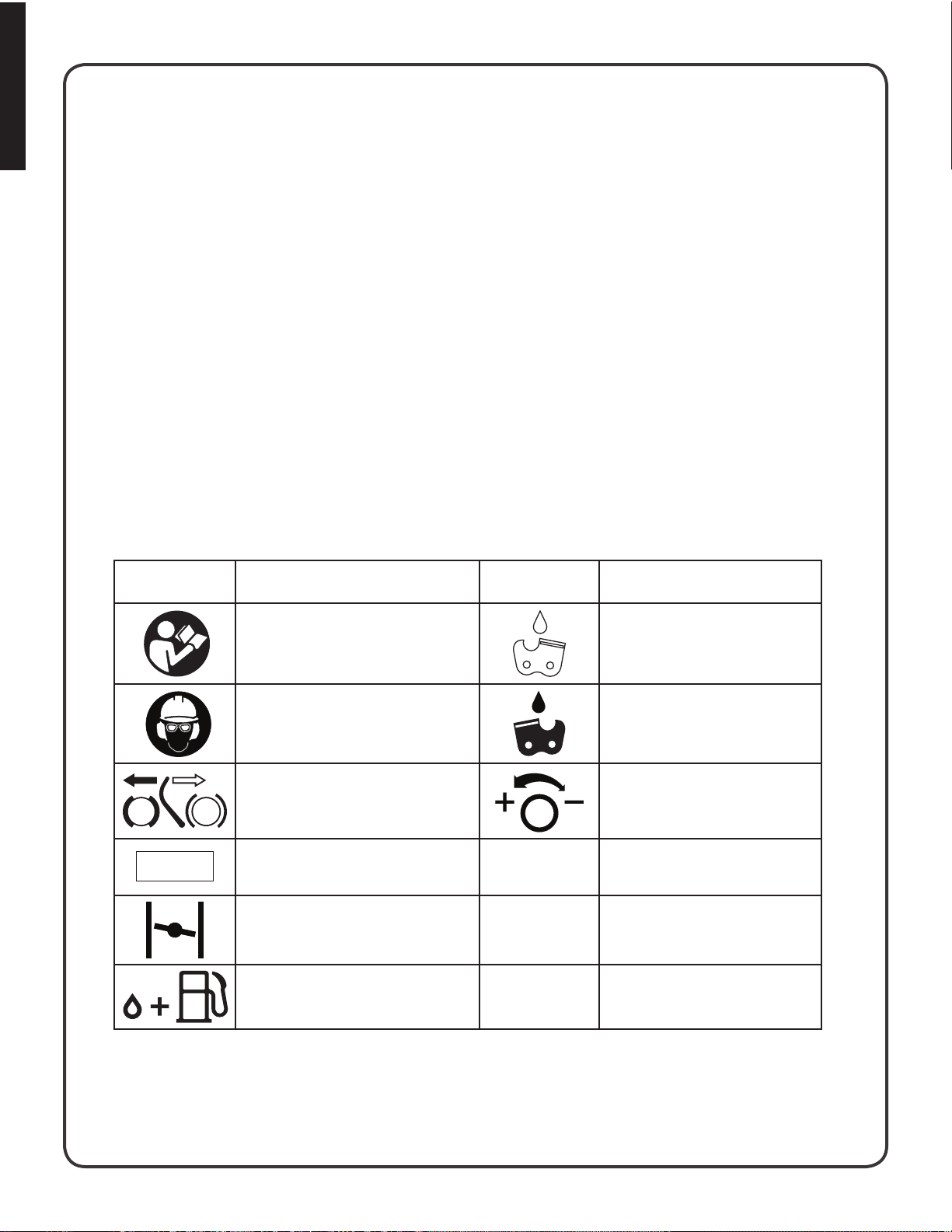
Symbol
form/shape
in t e R n a t i o n a l sy m b o l s
Symbol description/
application
Read and understand the
Operator’s Manual.
Wear eye, ear, and head protection Chain oil pump
Chain brake operation Chain oiler adjustment
Emergency stop
Choke control “Cold Start” position
(choke closed)
Symbol
form/shape
L
H
Symbol description/
application
Chain oil ll
Carburetor adjustment - low
speed mixture
Carburetor adjustment - high
speed mixture
4
Gasoline and oil mixture
T
Carburetor adjustment - idle
speed
Page 5

te C h n i C a l Da t a
Model 326T
Dimension L x W x H 277 x 245 x 214 mm (10.9 x 9.7 x 8.4 inch)
Weight Power head, dry 3.6 kg (7.9 lb) Without chain and guide bar
Engine Type Air-cooled, two-stroke, single cylinder
Displacement 32.6 (1.989 cu.in.)
Carburetor Diaphragm type
Magneto Flywheel magneto : CDI system
Spark Plug
Starter Recoil starter
Power transmission Automatic centrifugal clutch
Fuel Mixture ratio 50:1
Tank Capacity 310 ml (10.5 oz U.S.)
Oil Bar and chain Shindaiwa bar and chain oil (or motor oil)
Tank Capacity 290 ml (9.8 . oz. U.S.)
Lubrication Adjustable automatic oil pump
Guide bar / Saw chain Standard 14 in. (355 mm)
Optional
Standard features Top handle
Engine speeds Idle Speed 2,400 - 2,800
Clutch Engagement 4,000 - 4,600
Wide Open Throttle (WOT) 13,000 - 14,000
Kickback Safety Features Double Guard Low Kick Guide Bar
NGK BPM-8Y (Canada BPMR-8Y) .065 mm (.026 in.) Gap
12 in.(305 mm), 16 in.(406 mm)
Front hand guard
Anti-vibration device
Throttle control lockout
Chain catcher
Spark arrestor catalytic mufer
Low Kick Guard Link Saw Chain
Front Hand Guard/Chain Brake Lever
Chain Brake
Kick Guard
English
Specications subject to change without notice
5
Page 6
English
em i s s i o n Da t a
EMISSION CONTROL
EPA PhAsE 2 / C.A.R.B. TIER III
ENGINE FAMILY:
EMISSION COMPLIANCE PERIOD : 300 HRS.
THIS ENGINE MEETS U.S. EPA PH2 EXH AND 2007
AND
REGULATIONS FOR S.O.R.E.
FOR MAINTENANCE SPECIFICATIONS AND ADJUSTMENTS.
IMPORTANT ENGINE INFORMATION
7EXHS.0334KB DISPLACEMENT : 32.6 cc
LATER CALIFORNIA EXH AND EVAP EMISSION
REFER TO OWNER’S MANUAL
PRODUCT EMISSION DURABILITY
The 300 hour emission durability compliance period is the time span selected by the manufacturer certifying the engine emissions output meets applicable California and/or U.S. EP A emissions regulations, provided that approved maintenance procedures are followed as listed in the Maintenance Section of this manual.
The emission control system for the engine is EM/TWC (Engine
Modication and 3-way Catalyst) and for the fuel tank the Control
System is EVAP (Evaporative Emissions). Evaporative emission
may be applicable to California models only.
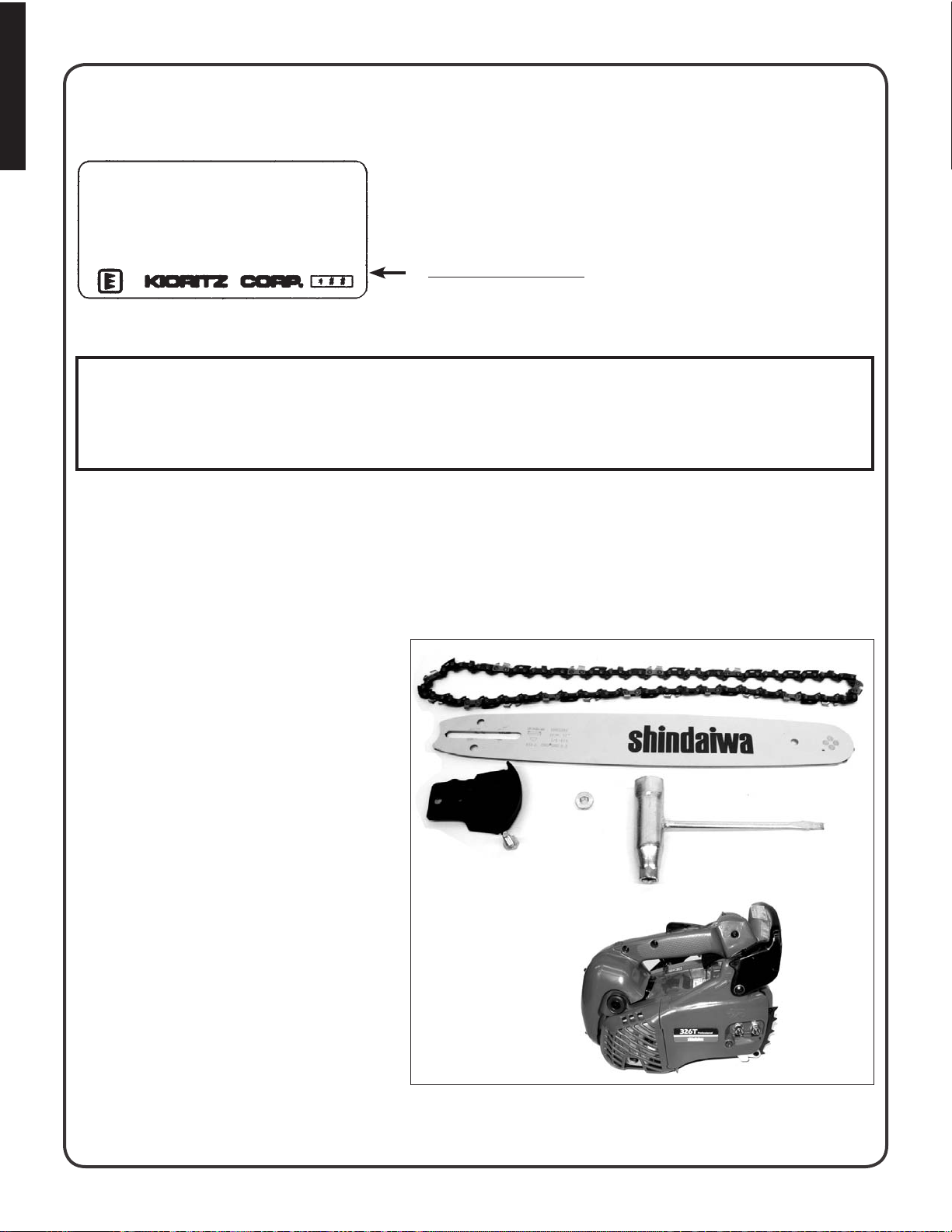
An Emission Control Label is located on the engine. (This is an
EXAMPLE ONLY, information on label varies by engine FAMILY).
De s C R i p t i o n
The Shindaiwa product you purchased has been factory pre-assembled for your convenience. Due to packaging restrictions, guide bar and saw chain installation and other assembly may be necessary.
After opening the carton, check for damage. Immediately notify your retailer or Shindaiwa Dealer of damaged or missing
parts. Use the contents list to check for missing parts.
CONTENTS
Power Head 1 -
Guide Bar1 -
Kick Guard1 -
Hex Head Bolt1 -
Hex Nut1 -
Saw Chain1 -
Instruction Manual1 -
Warranty Registration Card1 -
Limited Warranty Statement1 -
T-Wrench1 -
6
Page 7
15
English
no m e n C l a t u R e o f pa R t s
326T
10
11
12
14
13
1
9
8
7
2
4
3
5
6
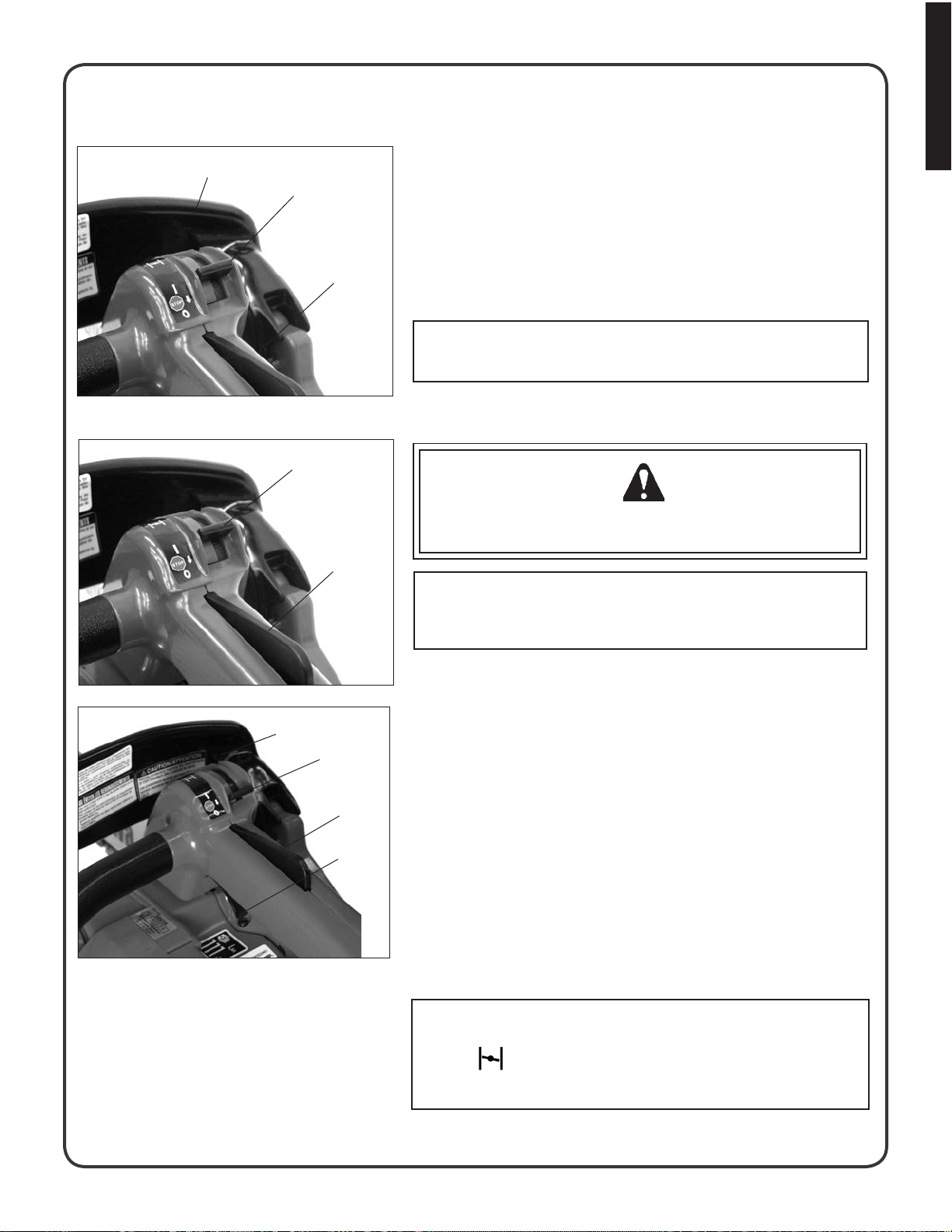
Hand guard (Chain brake actuating lever)1.
Ignition/Choke Lever2.
Throttle control trigger3.
Throttle control lockout4.
Air cleaner cover5.
Pull starter6.
Front handle7.
Oil tank cap8.
Fuel tank cap9.
Saw chain10.
Guide bar11.
Sprocket guard12.
Catalytic mufer13.
Spark Plug14.
Rear (Top) Handle15.
7
Page 8
English
CAUTION: This saw shall be used only by certified tree
service professionals. For safe operation follow all safety
precautions and instructions in the operator’s manual.
(Replacement operator’s manuals are available from your
Shindaiwa dealer. Hold chain saw firmly with both hands.
Cette tronçonneuse doit être utiliser seulement
par des professionnels de l’abattage. Pour un
travail en sécurité et les indications du manual
d’utilisation. (Le manual d’utilisation est
disponible chez votre agent Shindaiwa. Te nez
fermement la tronçonneuse des deux mains.
STOP
LABELS
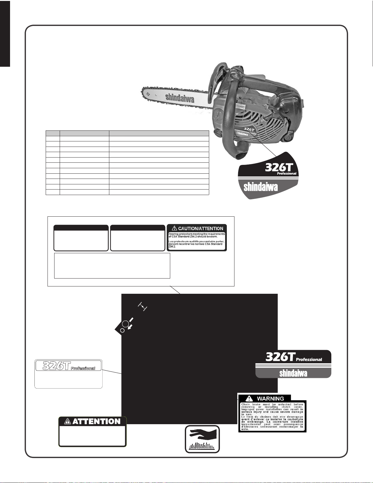
fo R Ca n a D i a n mo D e l s
326T
NO PART NUMBER DESCRIPTION
1 X505000460 KICKBACK LABEL (FRENCH)
2 X505000450 KICKBACK LABEL
3 89017639431 NOISE LABEL (ENGLISH / FRENCH)
4 X524002240 BAR & CHAIN LABEL
5 X503009450 326T ID LABEL
6 X505002071 WARNING LABEL
7 X505002310 HOT CAUTION LABEL
8 X505002580 ATTENTION LABEL
9 X503009480 326T ID / WARNING LABEL
10 X524001450 IGNITION SWITCH LABEL
11 X504000940 326T ID LABEL
*If a label is illegible, a replacement can be ordered from a
Shindaiwa dealer.
11
1
POUR ÉVITER LES REBONDISSEMENTS
Eviter touit contact entre le nez du guide-chaine 1.
et un objet quelconque.
Tout contact du nez peut provoquer un mouve-
2.
ment brusque vers le haut ou vers les bas et
entrainer de graves blessures.
Toujours employer lex deux mains pour opérer
3.
la scie á chaine.
REPLACEMENT BAR AND CHAIN NOTE: There may be other placement components for
REMPLACEMENT DU GUIDE ET DE LA CHAÎNE
GUIDE BAR CHAIN
PART NO. TYPE. LINKS
12" 120GPEA041 OREGON 91VG 45
14" 140GPEA041 OREGON 91VG 52
16" 160GPEA041 OREGON 91VG 57
2
TO AVOID KICKBACK
Contact of the guide bar tip with any object 1.
should be avoided.
2.
Tip contact may cause the guide bar to move
suddenly upward and backward which may
cause serious injury.
3.
Always use two hands when operating the
chain saw.
achieving kickback protection. For details, please refer
to the chain and bar combination sheet shown in in
the operator's manual
REMARQUE : Il y puet y avoir d'autres composantes, de
remplacement qui protèsent en cas de ebondissement.
Pour plus de détails, se réferér á la feuille sur les
combinasion de guide et de chaîne du manuel de
l'utilsaleur
3
4
10
5
9
6
8
8
7
Page 9
CAUTION: This saw shall be used only by certified tree
service professionals. For safe operation follow all safety
precautions and instructions in the operator’s manual.
(Replacement operator’s manuals are available from your
Shindaiwa dealer. Hold chain saw firmly with both hands.
STOP
Esta unidad puede ser peligrosa y producir
lesiones personales graves si no se usa en forma
adecuada. Para reducir ei riesgo de lesionarse,
los operadores, lost ayudantes,y los espectadores
deben leer y comprender el Manual Del Operador
y los Manuales de Seguridad que se entregan
escritos en espanol.
ADVERTENCIA PELIGRO
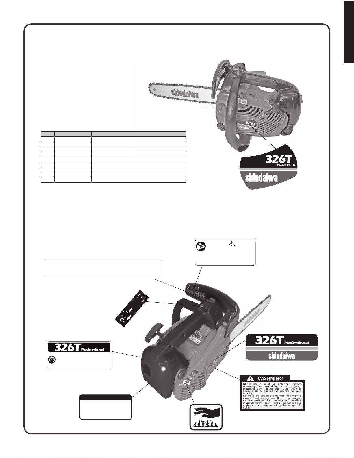
LABELS
fo R Ca l i f o R n i a m o D e l s
326T
NO PART NUMBER DESCRIPTION
1 89022839131
2 X524002220
3 X503009450
4 X505002061
5 X505002310
6 89019130131
7 X503009460
8 X524001450
9 X504000940
*If a label is illegible, a replacement can be ordered from a
Shindaiwa dealer.
CAUTION LABEL
BAR & CHAIN LABEL
326T ID LABEL
WARNING LABEL
HOT CAUTION LABEL
KICKBACK LABEL
326T ID / WARNING LABEL
IGNITION SWITCH LABEL
326T ID LABEL
English
9
2
GUIDE BAR CHAIN REPLACEMENT BAR AND CHAIN
PART NO. TYPE. LINKS
12" 120GPEA041 OREGON 91VG 45
14" 140GPEA041 OREGON 91VG 52
16" 160GPEA041 OREGON 91VG 57
NOTE: There may be other placement components for
achieving kickback protection. For details, please refer
to the chain and bar combination sheet shown in in
the operator's manual
7
6
TO AVOID KICKBACK
Contact of the guide bar tip with any object 1.
should be avoided.
2.
Tip contact may cause the guide bar to move
suddenly upward and backward which may
cause serious injury.
3.
Always use two hands when operating the
chain saw.
1
8
3
4
5
9
Page 10
English
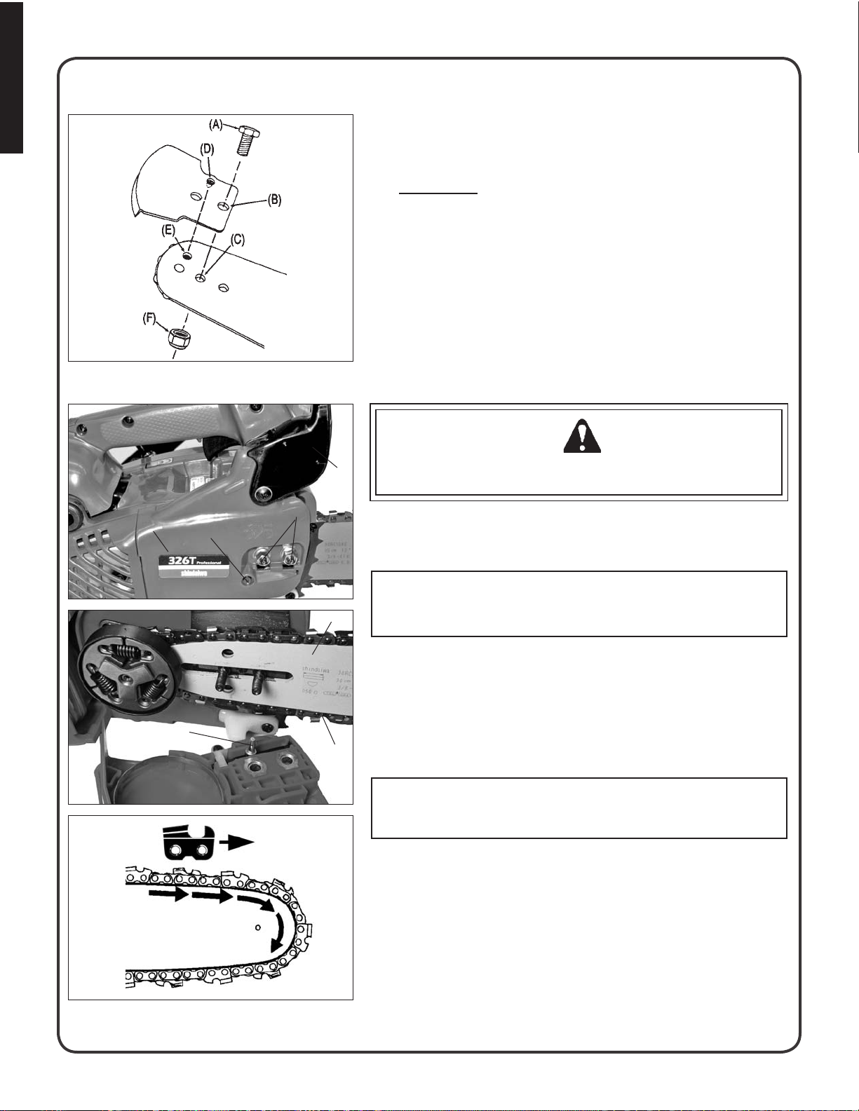
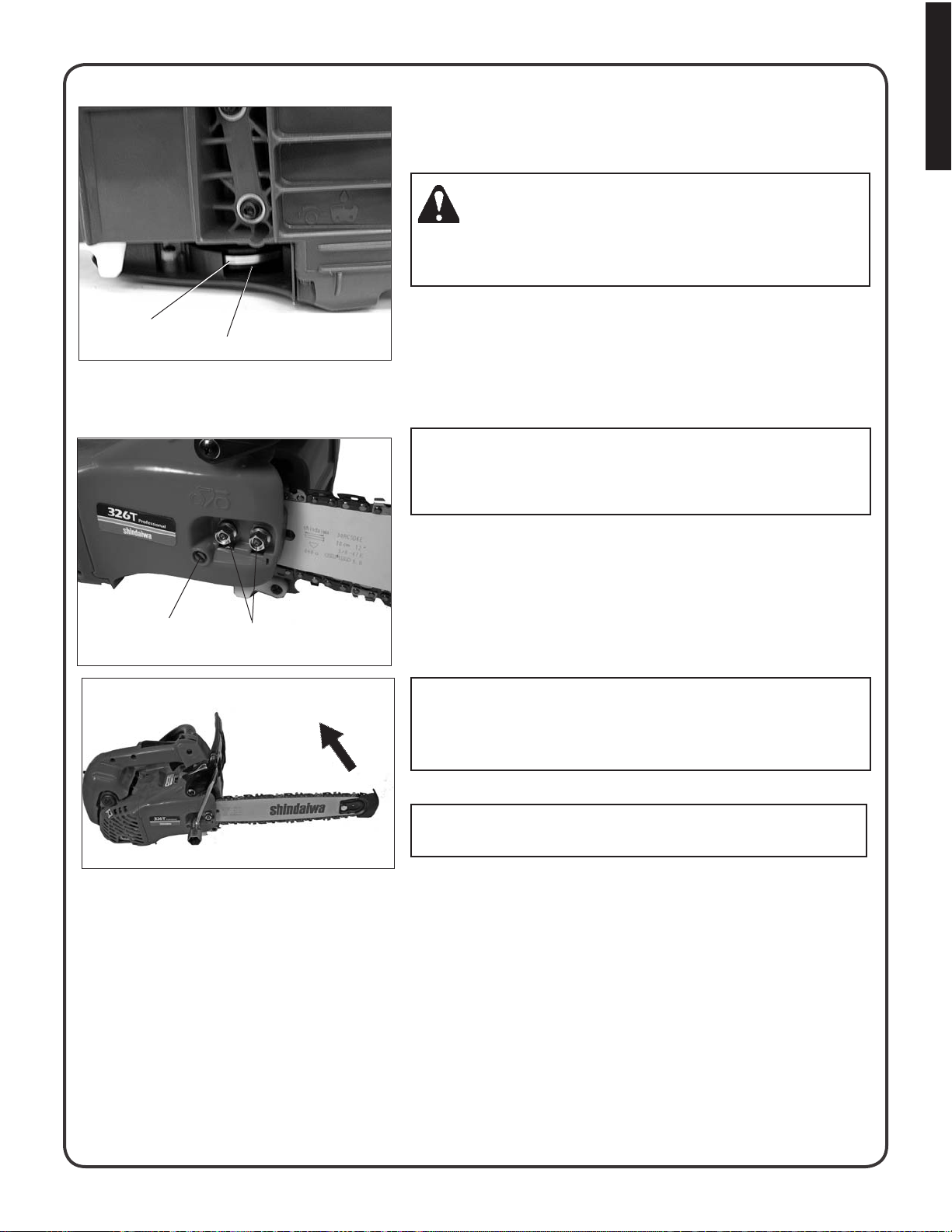
KICK GUARD® TO BAR INSTRUCTIONS
For saws with Kick Guard® and symmetrical or asymmetrical lowkick type guide bars.
1.
Install bolt (A) in rear hole (B) of Kick Guard® and through front
hole (C) in guide bar.
2. IMPORTANT: Dimple in Kick Guard® (D) must engage recess in
guide bar (E).
3.
Tighten nut (F) and bolt (A) until snug. Make certain Kick Guard®
is ush against guide bar.
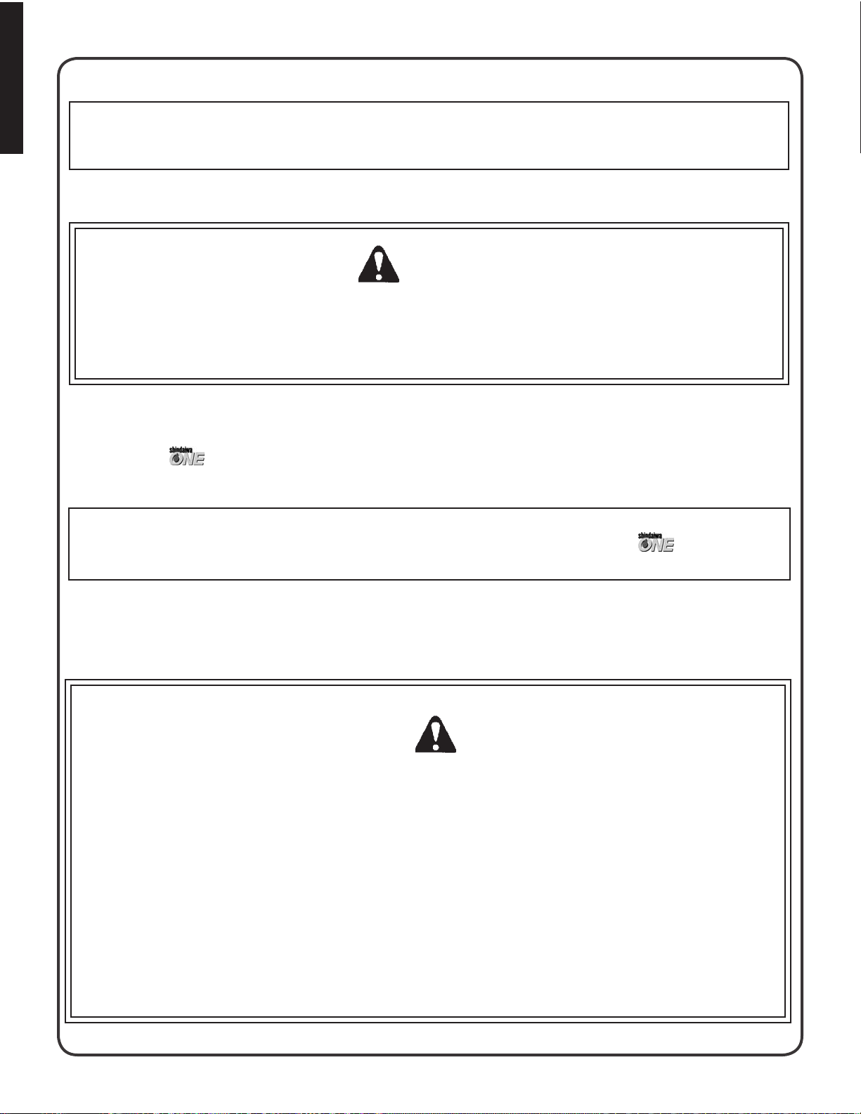
GUIDE BAR AND SAW CHAIN-INST ALL/ REMOVE
WARNING DANGER
G
Saw Chain is sharp! Always wear gloves when handling assembly, otherwise serious personal injury may result.
K
J
H
Move chain brake lever (G) fully rearward to unlock chain brake.1.
Remove two guide bar nuts (H). Turn tension adjustment screw (J) 2.
counterclockwise 2 to 3 turns if bar and chain are installed.
IMPORTANT
L
Always loosen guide bar nuts before turning chain tension adjuster, otherwise clutch cover and tensioner will be damaged
Push clutch cover (K) forward, pull rear of cover out slightly, then 3.
remove.
4.
Remove guide bar and saw chain if necessary.
Mount guide bar (L) on studs, and slide toward sprocket to make 5.
N
M
saw chain installation easier. Install saw chain (M) over clutch and
place around sprocket and guide bar as shown, with cutters on
top of guide bar facing forward.
NOTE: See “MAINTENANCE AND CARE” instructions for guide
bar, sprocket, and saw chain maintenance.
Align holes of clutch cover (K) with guide bar studs, and tensioner pin 6.
(N) with lower guide bar adjuster hole. Install cover, then press and
hold rear of cover to fully seat. Tighten guide bar nuts nger tight.
10
Page 11
English
Kick Guard to bar instructions, continued
Turn saw over and check brake band (O) for correct position 7.
around clutch drum (P). If brake band is not in place around drum,
remove clutch cover, make sure brake is released, and reinstall.
DANGER
Never operate saw if chain brake does not function properly, otherwise saw damage and serious personal injury could result. See
“Testing the Brake” instructions.
Adjust saw chain tension, as instructed in “Adjustment, Chain 8.
O
P
Tension”
ADJUSTMENT, CHAIN TENSION
IMPORTANT
Always loosen guide bar nuts before turning chain tension adjuster, otherwise clutch cover and tensioner will be damaged.
Remove air lter cover and spark plug lead.
1.
Loosen two guide bar nuts (H).2.
Hold the bar nose up, and turn the adjuster screw (J) clockwise 3.
until the chain touches the bottom of the bar.
4.
J
H
Tighten both guide bar nuts with bar nose held up.
Pull the saw chain around the guide bar by hand. Reduce chain 5.
tension, if you feel tight spots.
IMPORTANT!
Tighten guide bar nuts to 90 – 110 kgf/cm (80 – 95 in. lbs.) DO
NOT over-tighten nuts. Damage to saw may result.
Keep chain properly tensioned at all times.
6.
NOTE
All chains require frequent adjustments.
Replace spark plug lead and air lter cover.7.
11
Page 12
English
fu e l a n D lu b R i C a n t
NOTICE: Use of unmixed, improperly mixed, or fuel older than 90 days, (stale fuel), may cause hard starting, poor performance, or severe engine damage and void the product warranty. Read and follow instructions in the Storage section
of this manual.
FUEL STATEMENT
WARNING
Alternative fuels, such as E-20 (20% ethanol), E-85 (85% ethanol) or any fuels not meeting Shindaiwa requirements
are NOT approved for use in Shindaiwa 2-stroke gasoline engines. Use of alternative fuels may cause performance
problems, loss of power, overheating, fuel vapor lock, and unintended machine operation, including, but not limited
to, improper clutch engagement. Alternative fuels may also cause premature deterioration of fuel lines, gaskets, carburetors and other engine components.
Gasoline: Use 89 Octane [R+M/2] (mid grade or higher) gasoline known to be good quality. Gasoline may contain up to
10% Ethanol (grain alcohol) or 15% MTBE (methyl tertiary-butyl ether). Gasoline containing methanol (wood alcohol) is
NOT approved.
Two Stroke Oil:
requirements. Shindaiwa One is recommended for use in all Shindaiwa low emissions engines.Shindaiwa One also
includes a fuel stabilizer.
Oil is a registered JASO FC classified oil and also meets or exceeds ISO-L-EGD performance
IMPORTANT
Mix only enough fuel for your immediate needs! If fuel must be stored longer than 30 days and oil with fuel stabi-
lizer is not used, it should rst be treated with a fuel stabilizer such as STA-BIL™.
Handling Fuel
WARNING DANGER
Fuel is VERY ammable. Use extreme care when mixing, storing or handling or serious personal injury may result.
■
Use an approved fuel container.
DO NOT smoke near fuel. ■
DO NOT allow ames or sparks near fuel. ■
Fuel tanks/cans may be under pressure. Always loosen fuel caps slowly allowing pressure to equalize. ■
NEVER refuel a unit when the engine is HOT or RUNNING! ■
DO NOT ll fuel tanks indoors. ALWAYS ll fuel tanks outdoors over bare ground. ■
DO NOT overll fuel tank. Wipe up spills immediately. ■
Securely tighten fuel tank cap and close fuel container after refueling. ■
Inspect for fuel leakage. If fuel leakage is found, do not start or operate unit until leakage is repaired. ■
Move at least 3m (10 ft.) from refueling location before starting ■ the engine.
12
Page 13
Fuel and lubricant, continued
Mixing Instructions
English
Fuel Mix Chart
Fuel to Oil Mix-50:1 Ratio
U.S. METRIC
GAS OIL GAS OIL
Gallons Fl.oz. Liter cc.
1 2.6 4 80
2 5.2 8 160
5 13 20 400
TANK INDICATION
FUEL TANK OIL TANK
Fill an approved fuel container with half of the required amount of 1.
gasoline.
2.
Add the proper amount of 2-stroke oil to gasoline.
Close container and shake to mix oil with gasoline.3.
Add remaining gasoline, close fuel container, and remix.4.
IMPORTANT
Spilled fuel is a leading cause of hydrocarbon emissions. Some
states may require the use of automatic fuel shut-off containers to
reduce fuel spillage.
After use
DO NOT store a unit with fuel in its tank. Leaks can occur. Return
unused fuel to an approved fuel storage container.
Storage: Fuel storage laws vary by locality. Contact your local government for the laws affecting your area. As a precaution, store fuel in
an approved, airtight container. Store in a well-ventilated, unoccupied
building, away from sparks and ames.
IMPORTANT
Stored fuel ages. Do not mix more fuel than you expect to use in
thirty (30) days, ninety (90) days when a fuel stabilizer is added.
IMPORTANT
Stored two-stroke fuel may separate. ALWAYS shake fuel container
thoroughly before each use.
CHAIN LUBRICANT
Proper lubrication of the chain while in operation reduces friction
between the chain and the guide bar to a minimum and assures a longer service life.
■
Use bar and chain oil of high quality for this purpose.
Do not use used or reclaimed oil to avoid various oiler problems. ■
Use Shindaiwa bar and chain oil. ■
When Shindaiwa bar and chain oil is not available, use motor oil, ■
etc.
■
Use bar and chain oil of the following grades:
SAE NO. 30 ... in summer
SAE NO. 10 ... in winter or when cutting resinous trees.
■
When refueling, also rell chain oil.
13
Page 14
English
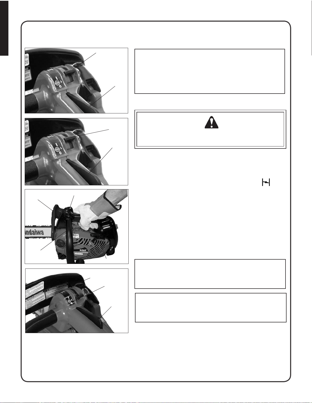
op e R a t i o n
A
IMPORTANT
This saw features a combination ignition/choke switch that automatically sets the throttle speed to fast idle for quick starting. Do not
squeeze trigger during cold starts until after unit has started, or fast
C
idle and choke settings will be released, and engine may not start.
STARTING COLD ENGINE
B
Make sure bar and chain are not touching anything when starting
the saw.
C
Move chain brake lever (E) fully forward to lock chain brake before 1.
starting.
2.
Fill the fuel tank with fuel. Do not over ll.
Fill the chain oil tank with lubricant. Do not over ll.3.
Move ignition/choke lever (A) forward to “close choke” (4. )
position.
E
D
G
F
E
G
5.
Lay unit on a at, clear area and keep bar and chain clear of all
obstacles. Hold top handle with one hand, and depress throttle
trigger lockout (C), but do not depress throttle trigger (D).
6.
Pull starter handle (F) several times until engine starts, or rst
starting sound is heard. (7 pulls maximum)
7.
Move ignition/choke lever back to “run” ( I ) position (B). (Do not
move to “Stop” position [G].) If necessary, start the engine.
8.
After engine starts, wait 5 seconds then depress and release throttle trigger (D). Allow unit to warm up at idle for several minutes.
NOTE
If engine does not start after 3 pulls with choke in “run” ( I ) position,
repeat cold start instructions 4-6.
WARNING DANGER
14
C
NOTE
Do not allow recoil handle to snap back against the casing. ■
Do not pull starter rope out to the maximum possible position. ■
Page 15
English
Operation, continued
STARTING WARM ENGINE
Ensure that there is fuel and chain oil in the tanks. 1.
E
A
C
Move chain brake lever (E) fully forward to lock chain brake 2.
before starting.
Lay unit on a at, clear area and keep bar and chain clear of all 3.
obstacles. Hold top handle with one hand, and depress throttle trigger
lockout (C), but do not depress throttle trigger.
Move ignition/choke lever (A) forward to “Run” position ( I ).4.
Pull starter handle. 5.
NOTE
If engine does not start after 5 pulls, use cold start procedure.
RUNNING
A
WARNING DANGER
The saw chain should not move at idle, otherwise serious personal injury may result.
C
NOTE
If saw chain moves, adjust carburetor according to “Carburetor Adjustment” instructions in this manual, or see your dealer.
After engine starts, allow it to return to idle and warm up before using. ■
Move chain brake lever (E) fully rearward to unlock chain brake. ■
E
A
C
D
Press throttle control lockout (C) then gradually squeeze throttle ■
trigger (D) to increase engine speed.
■
Saw chain starts moving when the engine reaches approximately
4200 rpm.
Ensure proper acceleration and lubrication of chain and bar. ■
Do not run the engine at high speed unnecessarily. ■
Be sure that saw chain stops moving when throttle trigger is ■
released.
STOPPING
Release throttle trigger (D) and move lever (A) rearward to STOP 1.
(O) position.
Move chain brake lever (E) fully forward to lock chain brake. 2.
NOTE
If engine does not stop, move ignition/choke lever forward to choke
position (
Shindaiwa dealer to check and repair stop switch before starting
the engine again
) to stop engine. Return the unit to your authorized
15
Page 16
English
Cu t t i n g in s t R u C t i o n s
GENERAL
In all circumstances the operation of the chain saw is a one-man
job. It is difficult at times to take care for your own safety, so don’t
assume the responsibility for a helper as well. After you have
learned the basic techniques of using the saw, your best aid will
be your own good common sense.
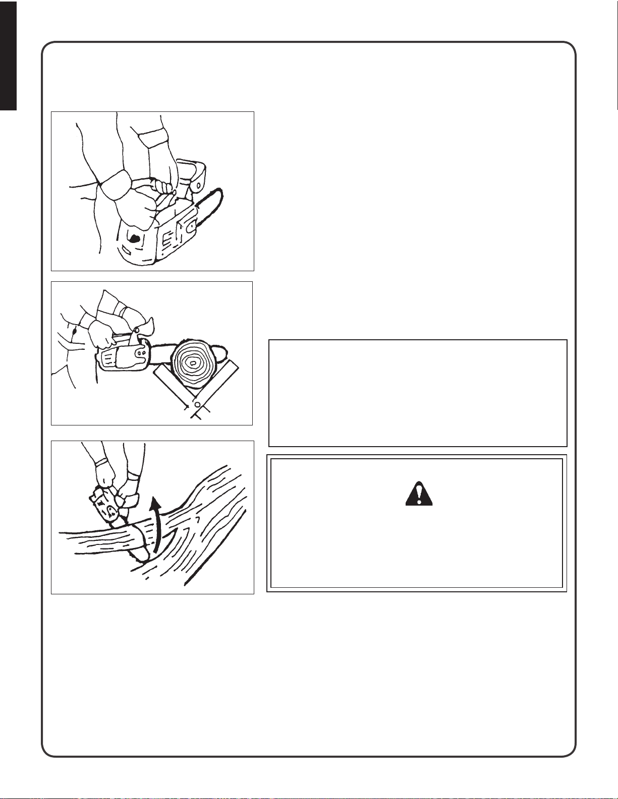
The accepted way to hold the saw is to stand to the left of the
saw with your left hand on the front handlebar and your right
hand on the rear handle so you can operate the throttle trigger
with your right index finger.
Before attempting to fell a tree, cut some small logs or limbs.
Become thoroughly familiar with the controls and the responses
of the saw.
Start the engine, see that it is running properly. Squeeze the trigger to open the throttle wide open and start the cut. If the chain is
properly sharpened, the cutting should be relatively effortless. It
is not necessary to press down hard to make the saw cut. Pushing the saw too hard will slow the engine and cutting will actually
be more difficult.
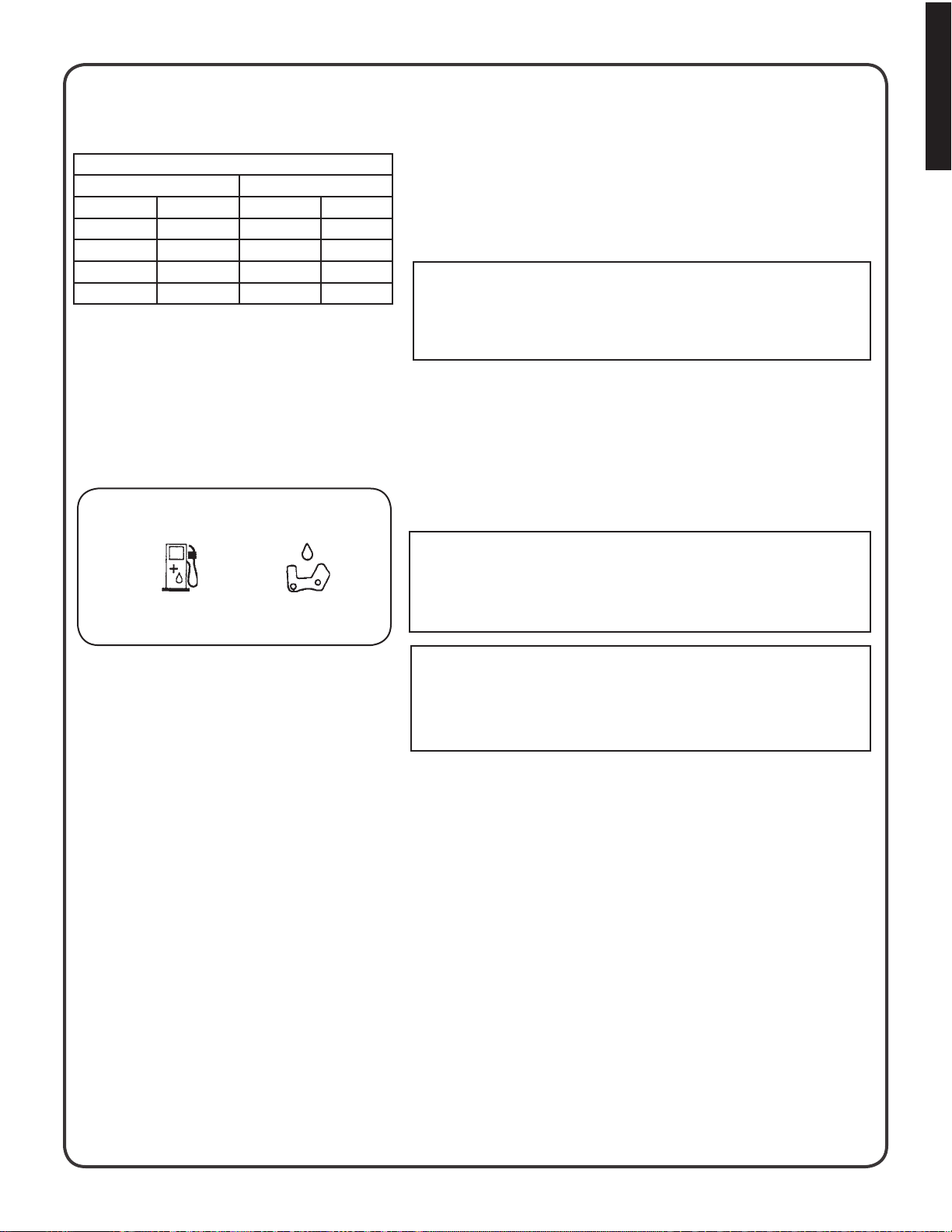
Kickback
NOTE
Some material may adversely affect the housings of your Shindaiwa
chain saw.
(Example: Palm Tree Acid, fertilizer, etc.) To avoid housing deterioration, carefully remove all packed saw dust around clutch and
guide bar area and wash with water. Coat metal parts with light oil.
WARNING DANGER
Do not let the tip of the bar touch anything while the engine is running. At cutting speed the chain is moving at a high rate of speed.
Should the tip contact a limb or log while the chain is moving, the
tip will be pushed upward with considerable force. This is known
as kickback. Avoid it!
16
Page 17
Select path of retreat
English
Cutting, continued
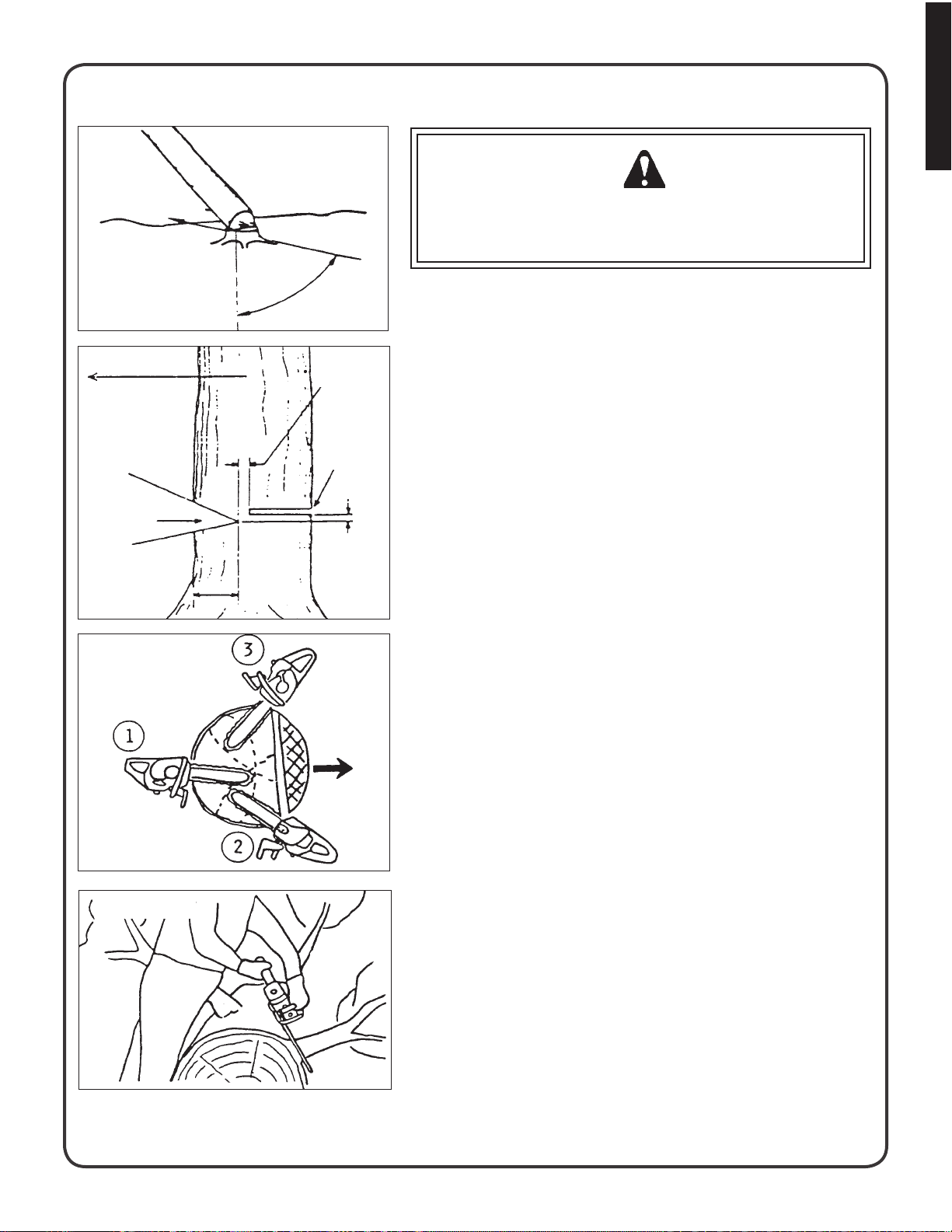
FELLING A TREE
DIRECTION
OF FALL
Direction of fall
First cut
Notch
Second cut
One-third tree
diameter
Felling big trees
2”
45°
Hinge
Felling cut
2”
WARNING DANGER
A falling tree can seriously damage anything it may hit: a car, a
house, a fence, a power line, or another tree. There are ways to
make a tree fall where you want it, so rst decide where that is!
Before cutting, clear the area around the tree. You will need good
footing while working and you should be able to work the saw
without hitting any obstacles. Next, select a path of retreat. When
the tree begins to fall you should retreat away from the direction
of fall at a 45 degree angle and at least 3m from the trunk to avoid
the trunk kicking back over the stump.
Begin the cut on the side to which the tree is to fall. Cut a notch
about 1/3 of the way into the tree as shown. The position of this
notch is important since the tree will try to fall “into” the notch. The
felling cut is made on the side opposite the notch and at a level
about 2” above the bottom of the notch. Do not try to cut through
to the notch with the felling cut. The remaining wood between the
notch cut and felling cut (about 2”) will act as a hinge when the
tree falls, guiding it in the desired direction. When the tree starts
to fall, kill the engine, place the saw on the ground and make your
retreat quickly.
To fell big trees with a diameter exceeding twice the bar length, start
the notching cuts from one side and draw the saw through to the
other side of the notch. Start the back cut on one side of the tree,
pivoting the saw through to form the desired hinge on that side.
LIMBING
Then remove the saw for the second cut. Insert the saw in the
rst cut, very carefully so as not to cause kickback. The nal cut is
made by drawing the saw forward in the cut to reach the hinge.
Limbing a fallen tree is much the same as bucking. Never limb on
the tree that you are standing. When limbing, caution is the word.
Be careful of the tip touching other limbs. Always use both hands.
17
Page 18
English
Cutting, continued
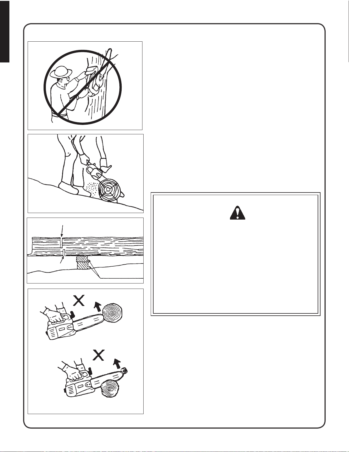
DON’T cut with saw overhead!
Uphill position
BUCKING
Don’t cut with the saw overhead or the bar in a vertical position. If the
saw should kick back you may not have good enough control to prevent possible injury.
Bucking is the sawing of a log or fallen tree into smaller pieces. There
are a few basic rules which apply to all bucking operations.
Keep both hands on the handles at all times.
Support logs if possible.
When cutting on a slope or hillside, always stand uphill.
Keep in mind that the wood is heavy and that it will bend and pinch
the saw if improperly supported.
The trunk will weaken at the point where you make the cut unless the
tree is lying on perfectly at ground or supported as shown.
If you make the cut with the tree on the ground, don’t let the saw’s
chain dig into the earth; it is harmful for the saw, and you stand a
good chance of being struck by ying debris. To cut the trunk, use
the bucking and two-cut sequence shown. The rst cut should be no
deeper than one-third the trunk diameter.
FINISH CUT
FIRST CUT
KICKBACK
■
Improper thrust cutting.
Board or at stones
WARNING DANGER
KICKBACK IS DANGEROUS
Kickback is generated when the rotation of the chain is arrested
for some reason. The most dangerous effect of this action occurs
when the nose of the bar contacts another object, the chain is
momentarily stopped and all the energy of the engine throws the
bar upwards and backwards towards the operator.
The chain saw industry and government agencies have
attempted to prescribe various safety devices, but the best protection is to avoid kickback.
Comply with the Safety Precautions as listed on page 2 and 3 of
this manual.
18
When the bar nose hits another ■
tree, etc.
Page 19

ma i n t e n a n C e a n D Ca R e
Your Shindaiwa unit is designed to provide many hours of trouble free service. Regular scheduled maintenance will help your
unit achieve that goal. If you are unsure or are not equipped with the necessary tools, you may want to take your unit to an
Shindaiwa Service Dealer for maintenance. To help you decide whether you want to DO-IT-YOURSELF or have the Shindaiwa Dealer do it, each maintenance task has been graded. If the task is not listed see your Shindaiwa dealer for repairs.
SKILL LEVELS
Level 1 = Easy to do. Most required tools come with unit.
Level 2 = Moderate difculty. Some specialized tools may be required.
Level 3 = Experience required. Specialized tools are required. Shindaiwa recommends that the unit be
returned to your Shindaiwa dealer for servicing.
MAINTENANCE INTERVALS
COMPONENT/SYSTEM MAINTENANCE
PROCEDURE
Air Filter Inspect/Clean 1 I / C * R *
Automatic Oiler Inspect/Adjust 1 I
Oil Filter Inspect/Replace 1 I / C *
Fuel System, leaks Inspect/Replace 1 I (1) * I (1) *
Fuel Filter Inspect 1 I *
Fuel Cap Gasket/O-ring Replace 1 R *
Guide Bar & oil holes Inspect/Clean/Lubricate 1 I / C * I
Saw Chain Inspect/Sharpen/
Replace/Tensioning
Sprocket Inspect/Replace 2 I *
Spark Plug Inspect/Clean 1 I / C/ R *
Cooling System Inspect/Clean 2 I / C
Mufer Spark Arrestor Inspect/Clean/Replace 2 I / C/ R *
Cylinder Exhaust Port Inspect/Clean/Decarbon 2 I / C
Recoil Starter Rope Inspect/Clean 1 I / C *
Screws/Nuts/Bolts Inspect/Tighten/Replace 1 I *
REQ’D
SKILL
LEVEL
2 I *
DAILY OR
BEFORE
USE
EVERY
REFUEL
3 MONTHS
OR 90
HOURS
YEARLY
English
“MAINTENANCE PROCEDURE LETTER CODES: I = INSPECT, R = REPLACE, C = CLEAN”
IMPORTANT NOTE - Time intervals shown are maximum. Actual use and your experience will determine the frequency
of required maintenance.
MAINTENANCE PROCEDURE NOTES:
(1) Low evaporative fuel tanks DO NOT require regular maintenance to maintain emission integrity.
* Replacement is recommended based on the nding of damage or wear during inspection.
19
Page 20
English
Maintenance, continued
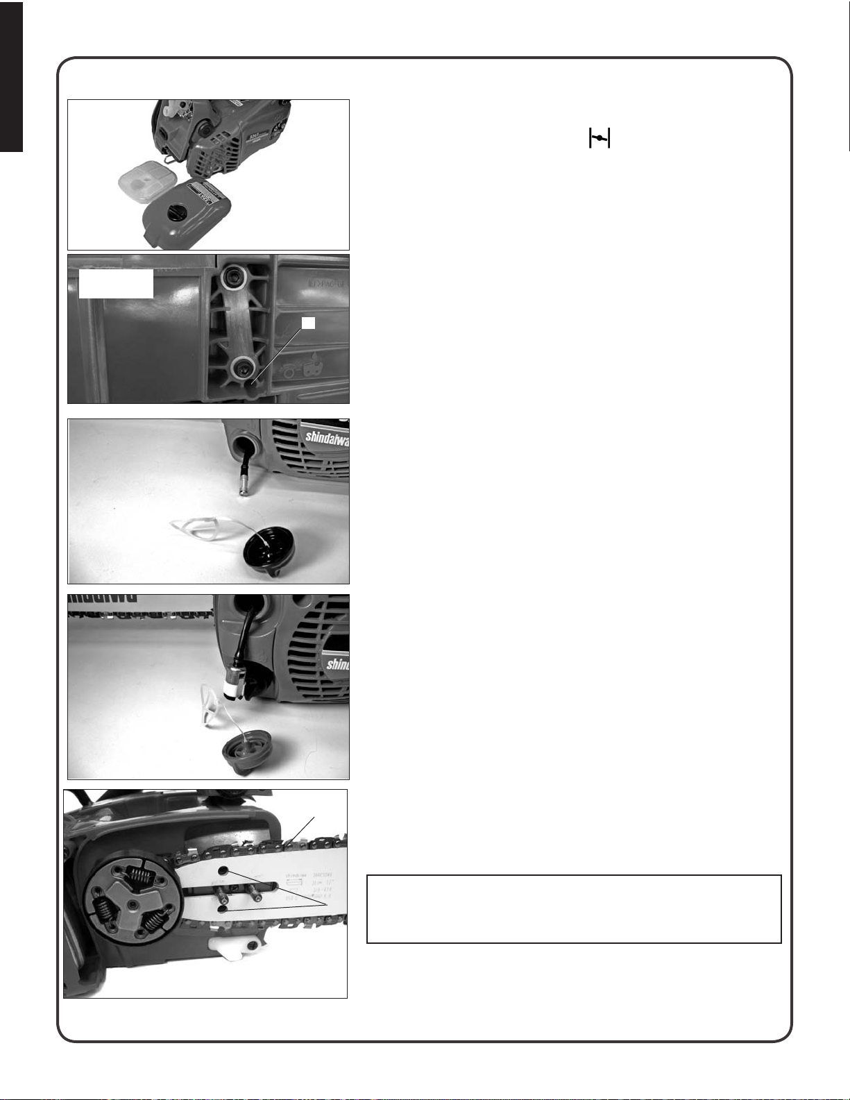
Air lter
Automatic
oiler
Oil strainer
AIR FILTER
Close choke (Cold Start Position [1. ]). This prevents dirt from
entering the carburetor throat when the air lter is removed. Brush
accumulated dirt from air cleaner area.
2.
Remove air lter cover. Brush dirt from inside cover.
Remove air lter and lightly brush debris from lter. Replace lter if it 3.
is damaged, fuel soaked, very dirty , or deformed.
Install air lter cover.4.
AUTOMATIC OILER
The discharge volume of the automatic oiler is adjusted to 6 to 7 cc/ ■
D
min (@ 7000 rpm) prior to shipment from the factory .
Always check oil discharge when in use. ■
Turn adjusting screw (D) counter-clockwise to increase oil volume, ■
clockwise to decrease oil volume.
OIL STRAINER
Check periodically. ■
Do not allow dust to enter oil tank.1.
Clogged oil strainer will affect the normal lubricating system2.
Using a wire bent into the shape of a hook, pull strainer out 3.
through oil port and inspect strainer.
4.
If the strainer is dirty, clean with suitable cleaning uid.
If the inside of the oil tank is dirty, rinse with suitable cleaning uid. 5.
Fuel strainer
FUEL STRAINER
Do not allow dust to enter fuel tank. 1.
Clogged strainer will cause difculty in starting engine or abnor-2.
malities in engine performance.
3.
Using a wire bent into the shape of a hook, pull strainer out
through gas port, and inspect strainer.
4.
If the strainer is dirty, clean with suitable cleaning uid.
If the inside of the tank is dirty, rinse with suitable cleaning uid. 5.
GUIDE BARS AND OIL HOLES
Follow instructions for “Guide Bar and Saw Chain: Install/Remove”. ■
A
B
Clean after each use ■
Clean the grooves (A) of the guide bar with a small screwdriver. -
Clean oil holes (B) with a wire. -
NOTE:
Symmetrical shaped Guide Bars should be inverted each time the
chain is removed to extend guide bar life
20
Guide bars and oil holes
Page 21
Maintenance, continued
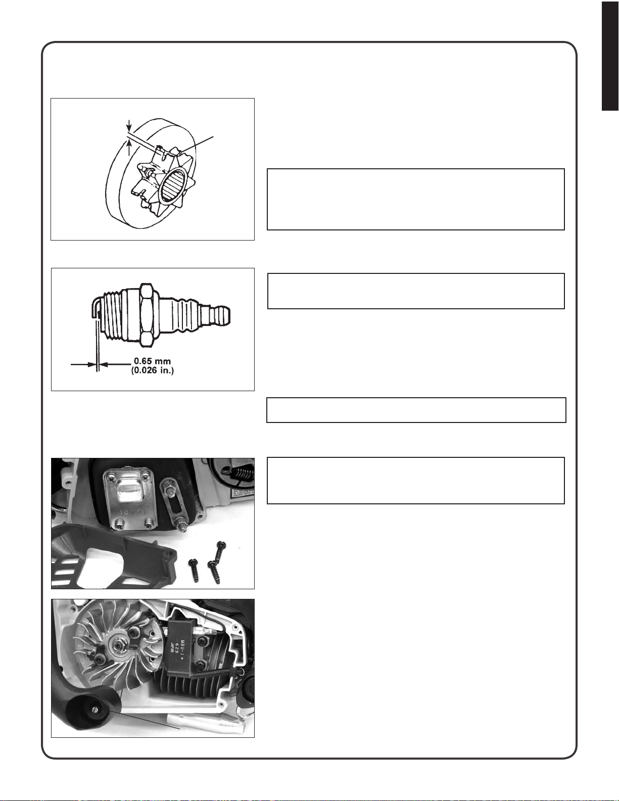
SPROCKET
English
Worn : 0.5 mm
A damaged sprocket (C) will cause premature damage or wear of ■
saw chain.
C
Clean sprocket, clutch and bar mount area before installation of bar. ■
Check sprocket when you install new chain. When outer diameter ■
of sprocket is worn 0.5mm (.020”) or more, replace it.
IMPORTANT
Some tree sap and resins are corrosive. Thoroughly wash the guide
bar and sprocket areas after each use, then coat metal parts with
light oil.
SPARK PLUG
Check periodically. ■
IMPORTANT: Use only NGK BPM-8Y spark plug (BPMR-8Y in
Canada) otherwise severe engine damage may occur.
Remove air cleaner cover.1.
Remove spark plug lead and spark plug.2.
Gap = 0.65 mm (0.026 in)3.
Replace if electrode is worn, or if the insulator is fouled by oil or 4.
other deposits
5.
Torque = 150 – 170 kg/cm (130 – 150 in. lb.)
IMPORTANT Do not over-torque
COOLING SYSTEM CLEANING
NOTE
See “Guide Bar and Saw Chain-Install/Remove Instructions for
sprocket guard removal/replacement instructions.
Mufer Side
Remove air lter cover and remove spark plug lead. 1.
Remove two guide bar nuts and remove sprocket guard. 2.
Remove three mufer cover screws and remove mufer cover. 3.
Using a stiff bristle cleaning brush (do not use a metal brush), 4.
remove debris from cylinder ns in mufer area.
5.
Assemble components in reverse order
Starter Side
Remove air lter cover and remove spark plug lead.
1.
Remove plastic plug in side handle mount (D), and remove side 2.
handle mounting screw.
3.
Remove four starter cover screws and remove starter cover.
Using a stiff bristle cleaning brush (do not use a metal brush), 4.
remove debris from ywheel and ignition coil area.
5.
D
Assemble components in reverse order.
21
Page 22
English
Maintenance, continued
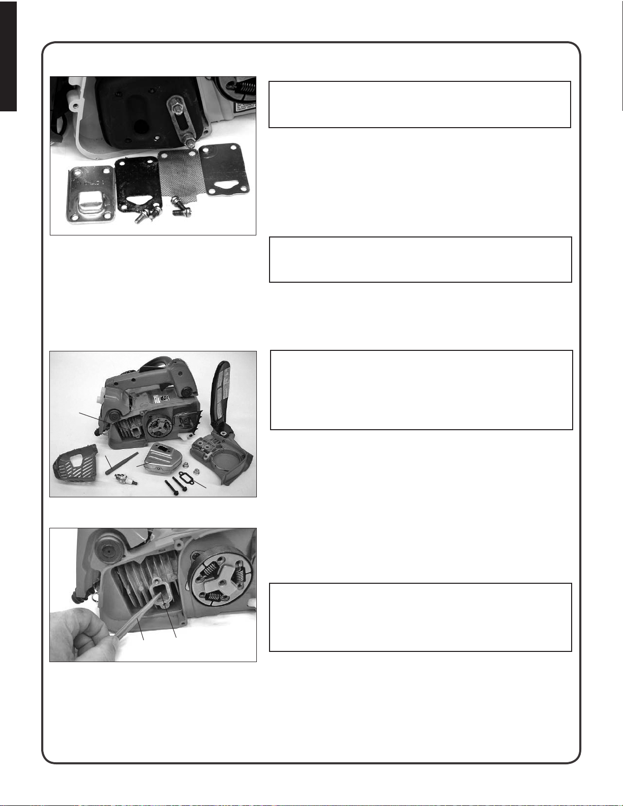
MUFFLER SPARK ARRESTER
IMPORTANT: Carbon deposits in mufer will cause a drop in engine
output and overheating. Spark arrester screen must be checked
periodically.
Remove air lter cover and remove spark plug lead. 1.
Remove two guide bar nuts and remove sprocket guard. 2.
Remove three mufer cover screws and remove mufer cover. 3.
Remove spark arrestor screen cover, gaskets, and screen from 4.
mufer body.
5.
Clean carbon deposits from mufer components.
Replace screen if it is cracked, plugged, or has holes burned through. 6.
NOTE: When cleaning carbon deposit, be careful not to damage the
catalytic element inside mufer.
Assemble components in reverse order. 7.
CYLINDER ExHAUST PORT
IMPORTANT :
cleaned of excess carbon every 3 months or 90 hours of operation in
order to maintain this engine within the emissions durability period.
Shindaiwa strongly recommends that you return your unit to your Shin-
D
C
A
B
daiwa dealer for this important maintenance service.
Exhaust Port Cleaning - Level 2
Tools required: Wood or plastic scraper, cross-head (Philips) screwdriver, 4 and 5 mm hex wrench
Parts Required: (as needed) mufer gasket
Remove spark plug lead from spark plug, and remove mufer
1.
cover (3 screws).
2.
Place piston at top dead center. Remove mufer ( A) and mufer
gasket (B ).
3.
Use a wood or plastic scraping tool (C) to clean deposits from cylinder exhaust port (D).
IMPORTANT
■
Never use a metal tool to scrape carbon from the exhaust port.
Do not scratch the cylinder or piston when cleaning the exhaust ■
C
D
port. Do not allow carbon particles to enter the cylinder.
The cylinder exhaust port must be inspected and
22
Inspect mufer gasket, and replace if damaged.4.
Install mufer gasket and mufer.5.
Install mufer cover and attach spark plug lead.6.
Replace the three mufer cover screws securely. If a torque 7.
wrench is available, torque the mufer cover screws to 10 - 20 kgf-
cm (1 - 2 N-m).
Page 23
Maintenance, continued
CARBUERATOR ADJUSTMENT
Engine Break-In
New engines must be operated a minimum duration of two tanks of fuel break-in before carburetor adjustments can be
made. During the break-in period your engine performance will increase and exhaust emissions will stabilize. Idle speed
can be adjusted as required.
BEFORE MAKING ADJUSTMENTS:
1.
The correct spark plug must be clean and properly gapped.
The air lter element must be clean and properly installed.2.
The mufer spark arrestor screen and exhaust port must be clear of carbon.3.
The standard bar and chain combination (refer to the section, Technical Data) must be installed to the power head, 4.
and properly tensioned.
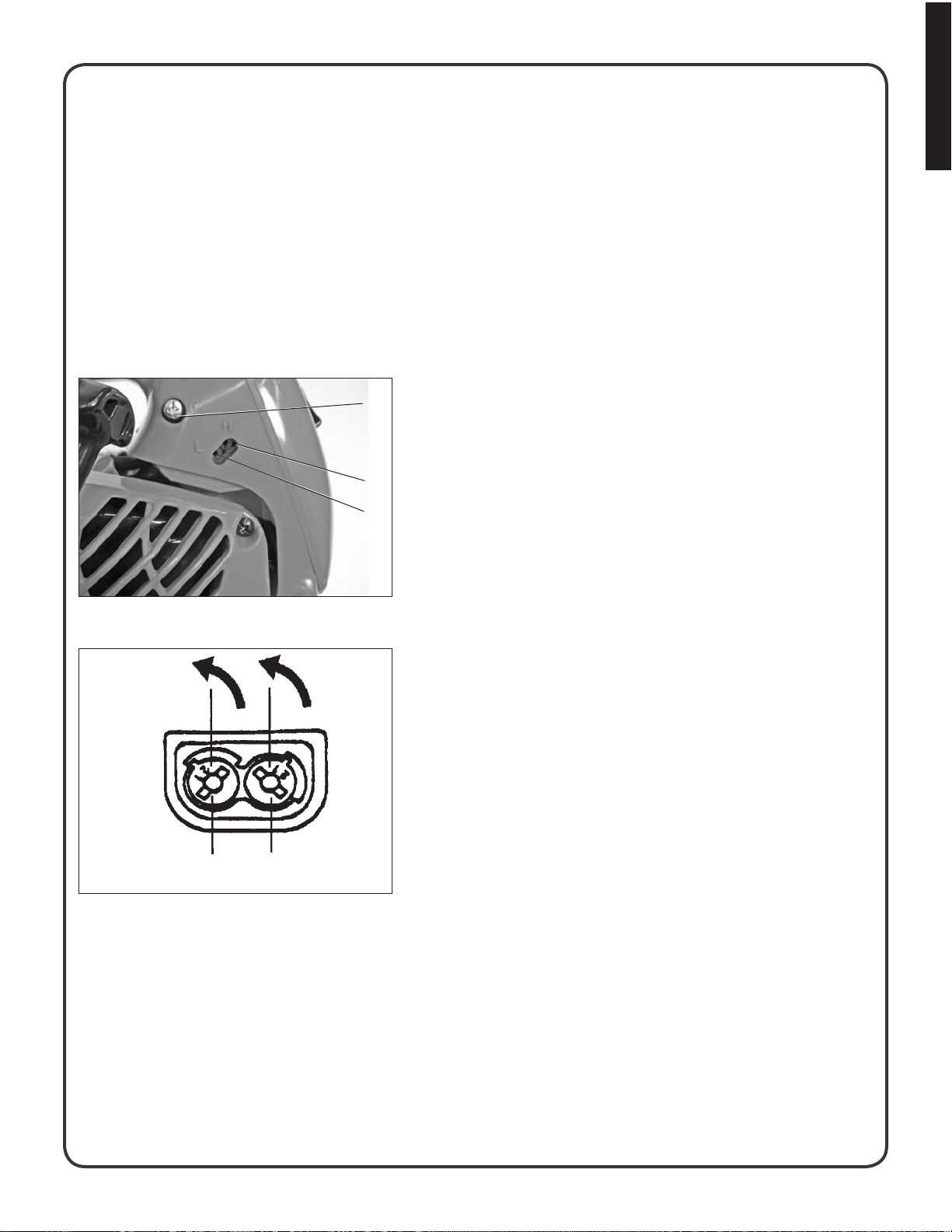
LOW ALTITUDE ADJUSTMENT
Engines that have been adjusted to operate at high altitudes must be
readjusted to operate properly at altitudes below 1100 feet.
C
1.
Start engine and run for several minutes to reach operating
temperature.
2.
Stop engine.
A
B
Start engine and turn the high-speed needle (A) rich (CCW) until 3.
the engine runs between 13,500 and 14,500 RPM. Then turn the
low-speed needle (B) rich (CCW) until the engine does not hesitate when accelerated.
DO NOT REMOVE LIMITER CAPS!
4.
Idle Speed Adjustment.
Turn “idle” speed adjustment screw (C) CW until the saw chain
begins to move, then turn the screw CCW until saw chain stops
moving. Turn screw CCW an additional 1/4 turn.
5.
Accelerate to full throttle for 2-3 seconds to clear excess fuel from
engine then return to idle. Accelerate to full throttle to check for
smooth transition from idle to full throttle. If engine stops or stalls
after full warm-up return the unit to your authorized Shindaiwa
dealer for adjustment.
English
low
high
HIGH ALTITUDE ADJUSTMENT
High altitude adjustment may be required for proper operation of this
engine above 1100 feet.
1.
Start engine and run for several minutes to reach operating
temperature.
2.
Stop engine.
Start engine and turn the high speed needle (A) lean (CW) until 3.
the engine runs between 13,500 and 14,500 RPM. Then turn the
low speed needle lean (B) (CW) until the engine does not hesitate when accelerated.
DO NOT REMOVE LIMITER CAPS!
4.
Idle Speed Adjustment.
Turn “idle” speed adjustment screw (C) CW until the saw chain
begins to move, then turn the screw CCW until saw chain stops
moving. Turn screw CCW an additional 1/4 turn.
5.
Accelerate to full throttle for 2-3 seconds to clear excess fuel from
engine then return to idle. Accelerate to full throttle to check for
smooth transition from idle to full throttle. If engine stops or stalls
after full warm-up return the unit to your authorized Shindaiwa
dealer for adjustment.
23
Page 24
English
Ch a i n a n D gu i D e ba R Co m b i n a t i o n s
The following combinations may be used on 326T.
Model Bar Length Low Kickback
Guard Bar
Bar P/N Chain P/N Links Type Pitch Gauge
12” 120GPEA041 91VG-45 45
326T
16” 160GPEA041 91VG-57 57
*Reduced nose radius symmetrical bars (OREGON name — Double Guard)
WARNING DANGER
Use of replacement saw chain and/or guide bar other than that specied, or operation without the “tip guard” in place,
may cause severe kickback resulting in serious injury.
Only use saw chain designated as “LOW-KICKBACK” that meets the ANSI B175.1-2000 Standard and the guide bar
specied.
Low Kickback Saw Chain
91VG 3/8” .05014” 140GPEA041 91VG-52 52
IMPORTANT
Chain and guide bar gauge size must be identical. Use Bar/Chain combinations shown in table above.
IMPORTANT
If your kick guard is damaged or lost, contact your Shindaiwa dealer for a replacement.
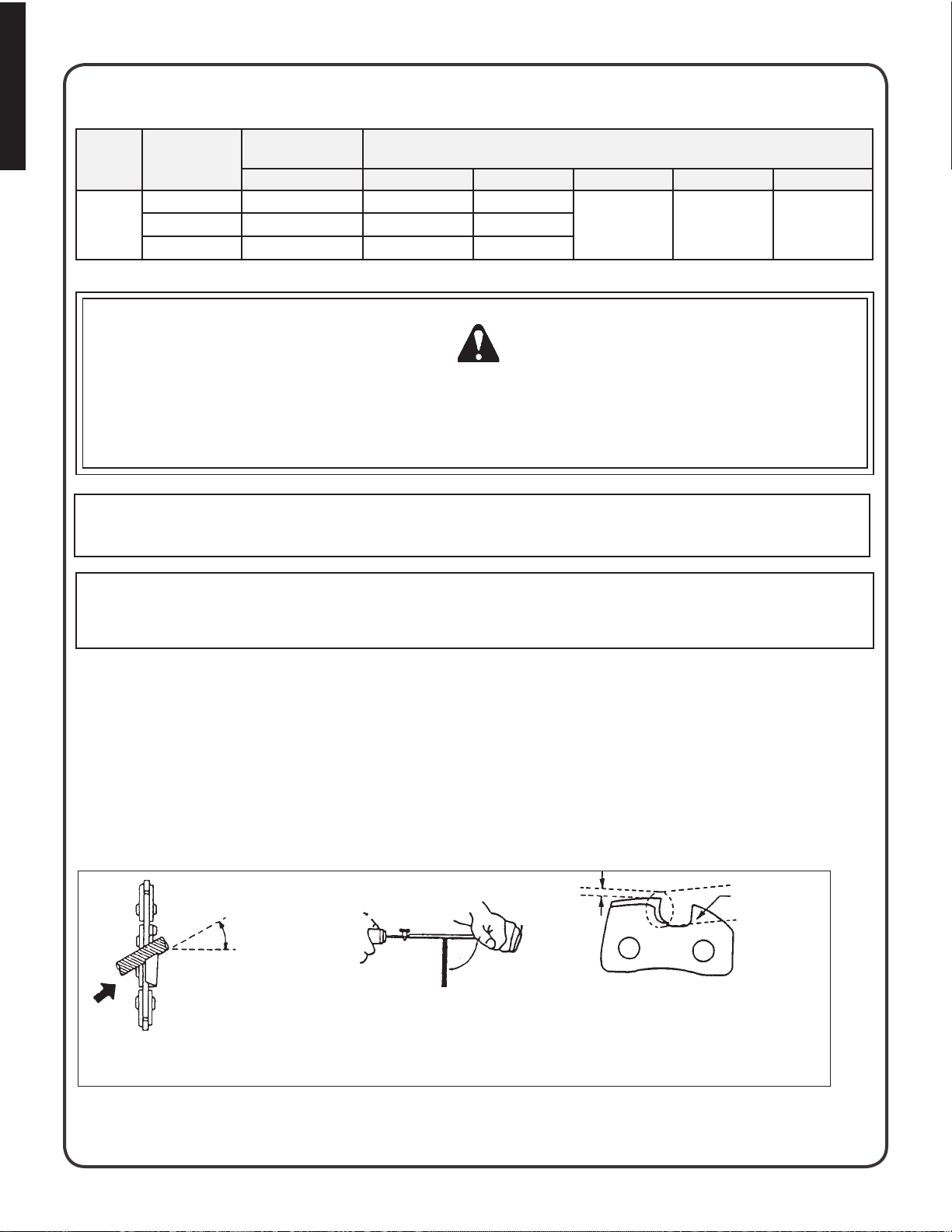
SETTING THE SAW CHAIN
For setting saw chains, round le (4 mm ø: 5/32”) and at le are used.
To keep correct position and correct angle, use the le holder. ■
Round le and at le are available from your Shindaiwa Dealer. -
File cutters as below. ■
Type : 91VG
30°
Keep this angle
90°
1/5
Depth gauge
24
PUSH FILE AS SHOWN
HOLD FILE HOLDER LEVEL
ONE FIFTH OF FILE DIAMETER REMAINS
To sharpen other type chain, follow chain manufacturer’s instructions
ABOVE CUTTER EDGE
Page 25

Place the depth gauge tool rmly on guide bar so that depth gauge protrudes. Then le top of depth gauge with ■
at le until at with top of the gauge tool.
-
Be sure to round off the front edge of the depth gauge.
Depth gauge tool
Properly led cutters are shown below. ■
Remove
until at
with tool
Round off
the edge
English
Top plate angle
30°
Side plate angle
80°
Top plate cutting angle
60°
Depth gauge
0.64 mm (0.025 in.)
When setting of the chain is nished, soak it in oil and wash away lings completely before using. ■
When chain has been led on the bar, supply sufcient oil to it, rotate the chain slowly to wash away the lings ■
before using again.
■
If the chain saw is operated with lings clogged in the groove, the saw chain and the guide bar will be damaged
prematurely
■
If the saw chain becomes soiled with resin, for instance, clean it with kerosene and soak it in oil.
(DRIVE LINK)
(SPROCKET)
CHAIN TYPE AND SPROCKET PITCH
Saw chain should be used with corresponding pitched sprocket. To
identify chain type and pitch of sprocket, check as follows.
Sprocket
Number
indicates
Chain type
Pitch
91
A
B
3/8A
Chain type number (A) is stamped on drive link. ■
Sprocket pitch (B) is stamped on clutch drum. ■
Parallel
Inspect and adjust every part of the chain saw. ■
Completely clean every part, and repair, if necessary. ■
Apply thin coating of oil on metal parts to prevent corrosion. -
Drain fuel tank, pull starter slowly a few times to drain fuel from carburetor. -
Pour a small amount of clean two-stroke oil into spark plug hole, pull starter 2 to 3 times, then leave the piston at TOP ■
DEAD CENTER.
■
Store in a dry area, free from dust.
st o R a g e af t e R us e
25
Page 26
English
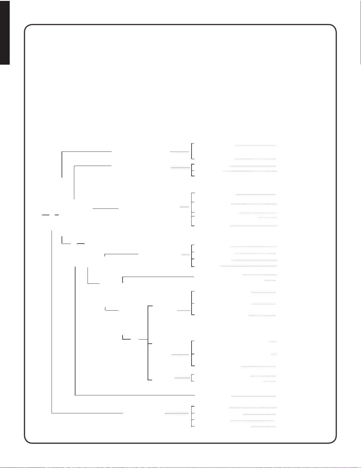
tR o u b l e s h o o t i n g
Poor performance of the engine and/or cutting mechanism can normally be prevented by carefully following these
instructions.
Poor performance can easily be corrected even by a beginner.
When the engine does not function properly check the following three (3) points rst.
Is the engine compression adequate?
■
Is fuel system in good condition and is enough fuel being supplied? ■
Is electrical system in good condition and is spark plug operating normally? ■
When there is serious trouble with the unit, do not try to repair it yourself but have your distributor or dealer do it for you.
For detailed TROUBLESHOOTING refer to tables 1 and 2. Locate the problem on the following charts and repair as
necessary.
Table 1
Engine cranks
There is fuel in the tank
Engine does not start (or, is difcult to start)
Fuel is not reaching carbuerator
Fuel is not reaching cylinder
No spark at high tension cord end
Fuel is reaching cylinder
Fuel is reaching carburetor
There is spark at high
tension cord end
No spark at plug
Fuel does not
keep running
Fuel strainer clogged
Fuel pipe clogged
Suction insufcient
Strainer clogged
Carburetor out of order
C.D.I. module defective
Ignition coil defective
Wire connection defective
High-tension cord connection defective
Switch is grounded
Insulator cracked
Spark gap incorrect
Covered with carbon
Fouled with fuel
Starting procedures incorrect
Low and high speed needle setting too lean
Metering lever spring too strong
Fuel pump diaphragm defective
Fuel passage clogged with dust
Clean.
Clean.
Make sufcient.
Clean.
Disassemble and check.
Remove and replace.
Remove and replace.
Reconnect.
Repair as necessary.
Switch on.
Replace plug.
Adjust.
Clean or replace.
Clean or replace.
Start correctly.
Readjust.
Readjust.
Replace.
Disassemble and clean.
26
There is spark at plug
Acceleration and
low speed function defective
Starting procedures correct
Carburetor
overow
Engine does not crank
Fuel leaking from xing surfaces of carburetor
Air valve, fuel tank cap does not work normally
Fuel pump does not operate
Fuel inlet needle clogged with dust
Metering spring not placed in dent of lever
Mufer sticky with fuel
Bearing damaged
Piston and/or cylinder deized
Crankshaft worn
Crankshaft contacting crankcase
Retighten all screws.
Replace or Clean.
Check impulse drilling.
Clean.
Correct.
Fuel mixture is too rich
Disassemble and replace.
Disassemble and replace.
Disassemble and replace.
Disassemble and replace.
Page 27
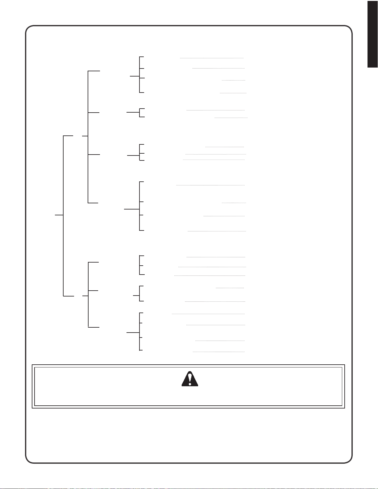
Table 2
English
Engine
overheated
Firing function
defective
Carburetor
Ouput (engine speed) insufcient
defective
Other
troubles
Improper fuel used
Spark plug defective (worn)
As cooling ns clogged, air does not pass well
Excessive deposits in combustion chamber
Plug damaged or fouled
Combustion poor due to defective wiring
High-speed needle setting incorrect
Carburetor overow
Air cleaner clogged
Compression insufcient (piston ring stuck or
worn out)
Cylinder chromium plating peeled or worn out
Exhaust port clogged with carbon
Throttle is not fully open
Use fuel with correct mixing ratio. Never use
gasoline of poor quality.
Replace.
Clean ns.
Disassemble and remove carbon.
Replace or clean.
Check wiring.
Readjust.
Refer to Table 1.
Clean as necessary.
Disassemble, check and replace if
necessary.
Replace cylinder
Clean as necessary.
Readjust.
Engine keeps running, but chain does not cut clean
Output (engine speed) sufcient
Chain does not cut
clean
Chain stops
(Clutch slips)
Chain poorly
lubricated
Chain tension incorrect
Chain wrongly set
Depth incorrect
Chain saw pressed against tree too rmly
Clutch shoe worn out
No oil in tank
Oil delivery incorrect
Oil contaminated with dust
Oil viscosity inappropriate
Adjust.
Set correctly.
Readjust.
Press lightly.
Replace.
Rell.
Adjust.
Rinse tank and ll with new oil..
Use oil with correct viscosity for summer or winter.
WARNING DANGER
Fuel vapors are extremely ammable and may cause re and/or explosion. Never test for ignition spark by
grounding spark plug near cylinder plug hole, otherwise serious personal injury may result.
27
Page 28

English
Co R R e C t us e o f Ch a i n bR a k e
The installation of a chain brake may be mandatory by law or as stipulated by insurance regulations in your area of opera-
tion. You should inquire through local government ofces, your employer or your local dealer to ensure that your chain saw
conforms to the required safety standard. Shindaiwa chain brakes have been designed and tested to comply with international safety standards as follows.
■
ANSI Standard B175.1-2000 Safety Requirement for chain saws
CSA Standard Z 62.1 CHAIN SAWS ■
WARNING DANGER
ANSI Standard B175.1-2000 stipulates that the brake shall stop the chain in 0.15 seconds maximum (.12 sec avg)
at full throttle. It is the responsibility of the Owner/Operator to ensure that the brake is serviced, adjusted and tested
strictly in accordance with the instructions as detailed herein in order to ensure that the brake performance is maintained in compliance with the Standard B175.1-2000.
Kickback Motion:
When the bar nose hits another tree, etc.
Improper thrust cutting.
INSTALLATION
Shindaiwa recommends that the chain brake should be serviced by an authorized Shindaiwa servicing dealer. ■
OPERATION
Set the lever in the released position before starting to cut. ■
If the brake is tripped by kick back reaction, the chain will stop. Immediately release the throttle to avoid possible dam- ■
age to the engine or clutch.
Do not attempt to operate the engine with the brake engaged.
■
Function:
When the lever is pushed forward, chain
brake instantly works to stop the chain
Release:
When the lever is fully pulled toward the
operator, brake is released.
TESTING THE BRAKE
Start the engine on a solid level surface and run at a fast idle until warm. ■
Hold the saw rmly by the handles and accelerate the engine to a fast idle. ■
Slowly operate the chain brake lever while holding the saw rmly on the ground. When the brake lever trips, the chain ■
should stop. Immediately release the throttle trigger.
IMPORTANT: Do not allow the saw to tip forward in order to avoid damage to the chain.
If the chain does not stop, immediately return the saw to your authorized Shindaiwa dealer for repair.
28
Page 29

Wa R R a n t y st a t e m e n t
Shindaiwa Corporation
EPA PHASE 2 / CALIFORNIA TIER III EMISSION
CONTROL WARRANTY STATEMENT - WARRANTY RIGHTS AND OBLIGATIONS
The Environmental Protection Agency (EPA) and the California Air
Resources Board (C.A.R.B.) and Shindaiwa Inc. are pleased to
explain the emission control system warranty on your EPA Phase 2
/ C.A.R.B. Tier III model year 2007 and later small off road engine
(SORE). New small off road engines must be designed, built and
equipped to meet stringent EPA and C.A.R.B. anti-smog standards.
Shindaiwa Inc. warrants the emission control system on your small
off road engine for the periods of time listed below provided there has
been no abuse, neglect or improper maintenance of your small off
road engine.
Your emission control system may include parts such as: carburetor/
fuel injected system, ignition system, catalytic converter, fuel tank,
fuel lines, fuel caps, valves, canisters, lters vapor hoses, clamps
connectors, and other associated components. For certain handheld products with engines less than or equal to 80cc displacement,
the fuel tank is subject to the C.A.R.B. evaporative emission control
warranty requirements of this section. Contact Shindaiwa Inc. for the
models covered under the C.A.R.B. evaporative emission regulations.
Where a warrantable condition exists, Shindaiwa Inc. or its authorized
service representative will repair your small off road engine at no cost
to you including diagnosis, parts and labor.
MANUFACTURER’S WARRANTY COVERAGE:
The 2007 and later small off road engines are warranted for two years
for certain emission related parts. If any emission-related part on your
engine is defective, the part will be repaired or replaced by Shindaiwa
Inc. or its authorized service representative.
OWNER’S WARRANTY RESPONSIBILITIES:
As the small off road engine owner, you are responsible for
■
the performance of the required maintenance listed in your
Operator’s Manual. Shindaiwa Inc. recommends that you retain all
receipts covering maintenance on your small off road engine, but
Shindaiwa Inc. cannot deny warranty solely for the lack of receipts
or for your failure to ensure the performance of all scheduled
maintenance.
As the small off road engine owner, you should however be aware
■
that Shindaiwa Inc. may deny you warranty coverage if your small
off road engine or a part has failed due to abuse, neglect, improper
maintenance or unapproved modications.
You are responsible for presenting your small off road engine to
Shindaiwa Inc.’s authorized service center as soon as a problem
exists. The warranty repairs should be completed in a reasonable
amount of time, not to exceed 30 days.
If you have any questions regarding your warranty rights and
responsibilities, you can contact Shindaiwa Inc. at 800-521-7733 or
www.shindaiwa.com
EPA PHASE 2 / CALIFORNIA TIER III EMISSIONS DEFECT
WARRANTY ExPLANATION
This is additional detailed information about the EPA PHASE 2/
CALIFORNIA TIER III EMISSIONS DEFECT WARRANTY for your
small off road engine.
WHAT DOES THIS WARRANTY COVER?
Shindaiwa Inc. warrants that your unit was designed, built and
equipped to conform with applicable EPA and California emissions
standards and that your unit is free from defects in material and
workmanship that would cause it to fail to conform with applicable
requirements within two (2) years. The warranty period begins on
the date the product is delivered to a retail purchaser. This is your
emission control system DEFECTS WARRANTY.
HOW WILL A COVERED PART BE CORRECTED?
If there is a defect in a part covered by this warranty, Shindaiwa Inc.’s
authorized service dealer will correct the defect.
You will not have to pay anything to have the part adjusted, repaired or
replaced. This includes any labor and diagnosis for warranted repairs
performed by the dealer. In addition, engine parts not expressly
covered under this warranty but whose failure is a result of a failure of
a covered part will be warranted.
Emissions System repairs covered under this warranty should be
completed in a reasonable time, not to exceed 30 days.
IMPORTANT
If the diagnosis reveals no defect, the emission defect warranty does
not apply.
WHAT PARTS ARE COVERED BY THE EPA PHASE 2/CALIFORNIA
TIER III 2007 & LATER SMALL OFF ROAD ENGINE EMISSIONS
DEFECT WARRANTY?
Any emission related part not scheduled for, “required
■
maintenance” (See Operator’s Manual, “SERVICE
MAINTENANCE SCHEDULE”) will be repaired or replaced
within the warranty period. The repaired or replaced part will be
warranted for the remaining Emissions Defect warranty period.
Any emission related part scheduled for replacement during
■
“required maintenance” (See Operator’s Manual, “SERVICE
MAINTENANCE SCHEDULE”) is warranted for the period of time
prior to the rst scheduled replacement point for that part. Any
such part repaired or replaced under warranty shall be warranted
for the remainder of the period prior to the rst scheduled
replacement point for that part.
Any Shindaiwa Inc. approved replacement part may be used in the
■
performance of any warranty maintenance or repairs on emissionrelated parts, and must be provided without charge if the part is
still under warranty.
Any replacement part that is equivalent in performance and
■
durability may be used in non-warranty maintenance or repairs,
and shall not reduce the warranty obligations of Shindaiwa Inc.
The owner is responsible for the performance of the required
■
maintenance described in the operator’s manual.
SPECIFIC EMISSION RELATED WARRANTED PARTS:
Choke
Carburetor (complete assembly or replaceable components)
Fuel Injection Assembly or replaceable components
Air Filter
Electronic Ignition System
Spark Plug
Catalytic Converter / Mufer Assembly
Fuel Tank (CARB only)
WHAT IS NOT COVERED BY THE EPA PHASE 2/CALIFORNIA
TIER III 2007 & LATER SMALL OFF ROAD ENGINE EMISSIONS
DEFECT WARRANTY?
Any failure caused by abuse, neglect, improper maintenance.
■
Any failure caused by unapproved modications, use of ■
unapproved add-on parts/modied parts or unapproved
accessories.
English
29
Page 30

NOTES
Shindaiwa Inc.
11975 S.W. Herman Rd.
Tualatin, Oregon 97062 USA
Telephone: 503 692-3070
Fax: 503 692-6696
www.shindaiwa.com
Shindaiwa Corporation
Head Ofce:
6-2-11, Ozuka-Nishi
Asaminami-Ku, Hiroshima
731-3167, Japan
Telephone: 81-82-849-2220
Fax: 81-82-849-2481
©2008 Shindaiwa, Inc.
Part Number 82085
Revision 8/08
Shindaiwa is a registered trademark of Shindaiwa, Inc.
Specications subject to change without notice.
Page 31

MANUAL DEL PROPIETARIO Y USUARIO DE SHINDAIWA
326T MOTOSIERRA
¡ADVERTENCIA!
Lea detenidamente este manual y familiarícese con su contenido.
Esta máquina está diseñada para cortar madera y viga. Utilícela únicamente para el propósito designado.
Número de parte 82085 Revisión 8/08
Page 32

Español
Re g l a s Pa R a l a OP e R a c i ó n se g u R a
A. Precaución De Seguridad Para El Contragolpe Para Los Usuarios De La Sierra De Cadena
ADVERTENCIA!
EL CONTRAGOLPE se puede producir cuando la nariz
o la punta de la barra de guía toca un objeto, o cuando
la madera obstruye y comprime la sierra de cadena al
cortar
En algunos casos, el contacto con la punta puede producir una REACCION de contramarcha rapidísima haciendo saltar la barra de guía hacia arriba y de vuelta
hacia el operador. Si se comprime la sierra de cadena a
lo largo de la parte superior de la barra de guía puede
empujaria rápidamenta hacia atrás hacia el operador.
Cualquiera de estas reacciones puede hacer que se
pierda el control de la sierra, lo que puede resultar en
graves daños personale.
El dispositivo Kick Guard® no está instala en la espada
cuando se compra una sierra de cadena Shindaiwa. El
protector Kick Guard® puede usarse en la mayoría de
las operaciones de corte, y se recomienda especialmente
para principiantes, propietarios de casas o personas que
vayan a usar la sierra de cadena por primera vez.
No confíe exclusivamente sobre los dispositivos de seguridad incorporó en su vio. Como un usuario de motosierra, usted debería tomar varios pasos para guardar sus
empleos de recorte libres del accidente o la herida.
1.
Si se sabe básicamente lo que es el contragolpe,
se puede reducir o eliminar el elemento de sorpresa. Las sorpresas repentinas contribuyen a los
accidentes.
Agarre la sierra rmemente y mantengala asi con 2.
ambas manos. Cuando el motor está funcionando,
use la mano derecha sobre el mango trasero y la
mano izquierda sobre el mango delantero. Agarrela
rmemente, con los pulgares y los dedos rodeando
los mangos de la sierra de cadena. Si agarra la sierra
rmemente se ayuda a reducir el contragolpe y a mantener el control de está. No la suelte.
Asegurese que el area en donde está cortando no 3.
tenga obstrucciones. No deje que la nariz de la barra
de quia se ponga en contacto con un leno, una rama
o cualquier otra obstruccion contra la que se pueda
golpear mientras se opera la sierra
4.
Corte a velocidades del motor altas.
No trate de alcanzar mas alia de lo que es posible 5.
alcanzar ni corte mas arriba de la altura del hombro.
Siga las instrucciones del fabricante para la aladura 6.
y el mantenimiento de la sierra de cadena.
7.
Use solamente las barras y cadenas de repuesto
especicadas por el fabricante, o su equivalente.
B. Otras Precauciones De Seguridad
¡No opere una sierra de cadena con una sola mano! 1.
Si se opera con una mano, el operador, los ayudantes, los espectadoes o cualquera combinación
de estas personas pueden sufrir daños graves. La
sierra de cadena está hecha para ser usada con las
dos manos.
2.
No opere una sierra de cadena cuando esté
fatigado.
3.
Use calzado de seguridad, ropa ceñida, guantes protectores y dispositivos de protección para los ojos,
los oídos y la cabeza. Lleve una cubierta protectora
para contener el cabello largo.
4.
Tenga cuidado cuando maneje el combustible.
Mueva la sierra de cadena a por lo menos 3 metros (10 pies) del punto de abastecimiento antes de
hacer arrancar el motor.
5.
No permita que otras personas estén cerca de la
sierra de cadena cuando la haga arrancar o corte
con élla. Mantenga a los espectadores y a los animales fuera del área de trabajo.
6.
No empiece a cortar hasta que tenga un área de trabajo despejada, una base segura para pisar y haya
planeado un camino de retirada del árbol que va a
caer.
7.
Mantenga todas las partes de su cuerpo lejos de la
sierra de cadena cuando el motor está funcionando.
8.
Antes de hacer arrancar el motor, asegúrese que la
cadena de la sierra no esté en contacto con ninguna
cosa.
9.
Transporte la sierra de cadena con el motor
detenido, con la barra de guía y la cadena de la
sierra hacia atrás y con el silenciador alejado de su
cuerpo.
10.
No opere una sierra de cadena que está dañada,
adjustada incorrectamente o que no está montada
completa y rmemente. Asegúrese que la cadena
de la sierra deja de moverse cuando se suelta el
gatillo del control de la aceleración.
SP_2
Page 33

Apague el motor antes de dejar la sierra de cadena en 11.
alguna parte.
12.
Tenga mucho cuidado cuando corte matorrales de
tamaño pequeño y árboles jóvenes, porque el material más ligero se puede coger en la cadena de la sierra
y serlanzado contra Ud. o lo puede hacer perder el
equilibrio.
13.
Cuando corte una rama que está bajo tensión, esté
alerta por si salta hacia átras, para que no lo golpee
cuando se libera la tensión en las bras de madera.
14.
Mantenga los mangos secos, limpios y sin aceite o
mezcla de combustible.
15.
Opere la sierra de cadena solamente en áreas bien
ventiladas.
16.
No opere la sierra de cadena en un árbol, a menos
que haya sido entrenado especialmente para hacerlo.
ADVERTENCIA PELIGRO
Todo el servicio de la sierra de cadena, a excepción de 17.
los artículos enumerados en las instrucciones de mantenimiento del manual del Instruccione, debe ser efectuado
por personal de servicio para la sierra de cadena competente. (Por Ejemplo, si se usan herramientas inadecuadas para remover el volante, o si se usa una herramienta
ínadecuada para sostenerlo mientras se remueve el
embrague, se puede producir un dano estructural en éste
lo que subsecuentemente puede hacer que éste se rompa.
Cuando transporte su sierra de cadena, use la funda 18.
de la guía de la barra apropiada.
Los silenciadoes del amortiguador de chispas aprobados 19.
de acuerdo al Standard SAE J335b, son estándar en las
sierras de cadena Shindaiwa para reducir la posibilidad
de incendios forestales. No opere la sierra de cadena
con un silenciador suelto o defectuoso. No remueva la
rejilla del amortiguador de chispas.
Español
Durante la operación, el silenciador o el silenciador catalítico y la tapa circundante se calientan. ■
No cuelgue nunca la sierra por un cable con el motor en marcha. ■
Use siempre la sierra por el lado derShindaiwa del cuerpo - No la use NUNCA por el lado izquierdo. ■
Lleve siempre ropa de seguridad apropiada para protegerse la parte inferior del cuerpo contra la cadena alada y ■
el silenciador caliente de la sierra.
■
Mantenga siempre limpia de residuos inamables el área de escape durante el transporte o almacenamiento, ya
que de lo contrario se pueden producir lesiones personales graves o daños materiales importantes.
ADVERTENCIA PELIGRO
Usar componentes de repuesto inadecuados o remover los dispositivos de seguridad son las lesiones graves o ■
fatales.
SP_3
Page 34

Español
STOP
cO n t e n t s
Reglas Para la Operación Segura ............................................................................................................................. SP_2
Símbolos internacionales
Datos Técnicos
Datos Emisiones......................................................................................................................................................... SP_6
Descripción
control de emisiones ................................................................................................................................................. SP_6
Nomenclatura de las Partes
Etiqueta
Combustible y lubricante
Instruccións para el Corte
Mantenimiento y cuidado
Combinaciones de la Cadena y Guía de la Barra
Almacenamiento
Identicación de Problemas
Uso Correcto del Freno de la Cadena
Declaratión de la Garantía
.......................................................................................................................................................................SP_8
........................................................................................................................................................... SP_5
................................................................................................................................................................. SP_6
....................................................................................................................................................... SP_25
.......................................................................................................................................... SP_4
......................................................................................................................................SP_7
......................................................................................................................................... SP_12
....................................................................................................................................... SP_16
........................................................................................................................................SP_19
.................................................................................................. SP_24
.................................................................................................................................... SP_26
....................................................................................................................SP_28
...................................................................................................................................... SP_29
Forma
de los
simbolos
sí m b O l O s i n t e R n a c i O n a l e s
Simbolo descripción/
aplicación
LEA CUIDADOSAMENTE EL
INSTRUCCIONES
Utilice siempre protecciones en
las orejas, ojos y cabeza.
Funcionamiento del freno de
sierra
Parada de emergencia
Control del estrangulador
“arranque en frio” posición
(Estrangulador Cierra)
Forma
de los
simbolos
L
H
Simbolo descripción/
aplicación
Llene de aceite para sierra
Bomba de aceite
Ajuste del lubricador de sierra
Ajuste del carburador - Mezcla
de baja velocidad
Ajuste del carburador - Mezcla
de alta velocidad
SP_4
Mezclas de gasolina y aceite
T
Ajuste del carburador -
Velocidad de ralenti
Page 35

Da t O s té c n i c O s
Model 326T
Long. x Ancho x alturo 277 x 245 x 214 mm (10.9 x 9.7 x 8.4 inch)
Pesa
Motor tipo Cilindro simple, de dos carreras, engrado por aire
Combustible propoción de la
Aceite barra y cadena Aceite de la barra y cadena Shindaiwa (o aceite del motor)
Barra de guia / Cadena de la
sierra
CaracterÍsticas estándar Mango superior
Velocidades del motor tr/min Marcha mínima 2,400 - 2,800
Caracteristicas de suguridad
para el controgolpe
Los datos técnicos están sujetos a cambios sin aviso.
cabezal de fuerza,
seco
desplazamiento 32.6 (1.989 pulg
carburador Tipo de diafragma
Magneto Magneta delvolane: sistema CDI
bujía NGK BPM-8Y (Canada BPMR-8Y) .065 mm (.026 in.) espacio
arrancador Arrancador de culateo
trasmisión de fuerza Automatic centrifugal clutch
mescla
capacidad del tanque 310 ml (10.5 onzas uidas)
capacidad del tanque 290 ml (9.8 . oz. U.S.)
lubricación bomba de aceite automática ajustable
estándar 355 mm / 14 pulg.
opciónal 305 mm / 12 pulg., 406 mm / 16pulg.
Velocidad de
embragado
Plena aceleración
(WOT)
3.6 kg (7.9 lb) Sin cadena y barra de guia
3
.)
50:1
protección manual delantera
Dispositivo antivibración
Seguro del control de la aceleración
Freno de la cadena
Silenciador del amortiguador de chispas
4,000 - 4,600
13,000 - 14,000
Guard Double barra de guía amrreste de contragolpe
cadena de sierra de tipo eslabón
protección manual delantera
freno de la cadena
protector contra retroceso
Español
SP_5
Page 36

Español
Da t O s em i s i O n e s
c O n t R O l D e e m i s i O n e s
INFORMACIÓN IMPORTANTE DEL MOTOR
FAMILIA DE MOTORES: 7EHXS.0334KB CILINDRADA: 32.6 cc
PERIODO DE LA CONFORMIDAD PARA LA EMISIONES : 300
HORAS.ESTE MOTOR CUMPLE CON LA FASE 2 DE EMISIONES
DE ESCAPE DE LA EPA DE EE.UU. Y LAS REGULACIONES DE
EMISIONES DE ESCAPE DE CALIFORNIA DE 2007 Y POSTERIORES
Y LAS REGULACIONES DE EMISONES EVAPORATIVAS PARA
MOTORES PEQUEÑOS QUE NO SON PARA TRANSPORTE
(S.O.R.E.) CONSULTE EN EL MANUAL DEL PROPIETARIO LAS
ESPECIFICACIONES Y AJUSTES DE MANTENIMIENTO.
DURABILIDAD DE LAS EMISIONES DEL PRODUCTO
El período de durabilidad de emisiones de 300 horas es el tiempo seleccionado por el fabricante certicando que las emisiones
de salida del motor cumplen con las regulaciones de emisiones aplicables, siempre que se sigan los procedimientos de mantenimiento aprobados según se indican en la sección de mantenimiento de este manual.
Fase 2 de la EPA / Nivel III de C.A.R.B
El sistema de control de emisiones para el motor es EM/TWC (modicación
del motor y catalizador de 3 vías) y para el depósito de combustible es el
sistema de control es EVAP (emisiones evaporativas). Las emisiones evapo-
rativas pueden aplicarse a modelos de California solamente.
Hay una etiqueta de control de emisiones ubicada en el motor. (Éste es un
EJEMPLO SOLAMENTE, la información de la etiqueta varía por FAMILIA
de motores).
De s c R i P c i ó n
El producto Shindaiwa que ha comprado se ha montado en fábrica para su conveniencia. Debido a restricciones de
empacado, tal vez sea necesario instalar el protector y efectuar otros montajes.
Después de abrir la caja de cartón, compruebe si está dañada. Notique inmediatamente a la tienda o distribuidor Shindaiwa en
caso de que haya piezas dañadas o que falten. Use la lista de contenido para comprobar las piezas que faltan.
CONTENIDO
Cabezal de impulsión 1 -
Barra de guía1 -
Protector contra retroceso1 -
Perno de cabeza hexagonal1 -
Tuerca hexagonal1 -
Cadena de la sierra1 -
Manual del instruccione1 -
Tarjeta de registro de la garantía 1 -
Declaración de garantía limitada 1 -
Combinación de destornillador y llave de cubo 1 -
SP_6
Page 37

nO m e n c l a t u R a D e l a s Pa R t e s
326T
15
10
Español
11
12
14
13
1
9
8
7
2
4
3
5
6
Protección manual (planca 1.
activadora del freno de la
cadena)
2.
Palanca de encendido/
estrangulador
3.
Gatillo del control de la
aceleración
4.
Seguro del control de la
aceleración
Cubierta del limpiador de aire5.
Arranque de tiro6.
Mango delantero7.
Tapa del estanque de aceite8.
Tapa del estanque de 9.
combustible
10.
Cadena de la sierra
Barra de guía11.
Protección de la rueda 12.
dentada
13.
Silenciador catalitico
Bujía14.
Manija (superior) de la parte 15.
trasera
SP_7
Page 38

Español
CAUTION: This saw shall be used only by certified tree
service professionals. For safe operation follow all safety
precautions and instructions in the operator’s manual.
(Replacement operator’s manuals are available from your
Shindaiwa dealer. Hold chain saw firmly with both hands.
Cette tronçonneuse doit être utiliser seulement
par des professionnels de l’abattage. Pour un
travail en sécurité et les indications du manual
d’utilisation. (Le manual d’utilisation est
disponible chez votre agent Shindaiwa. Te nez
fermement la tronçonneuse des deux mains.
STOP
et i q u e t a
P a R a m O D e l O s c a n a D i e n s e s
326T
NO NúMERO DE PARTE DESCRIPCIÓN
1 X505000460 ETIQUETA CONTRAGOLPE (FRANCÉS)
2 X505000450 ETIQUETA CONTRAGOLPE
3 89017639431 ETIQUETA RUIDO (INGLÉS / FRANCÉS)
4 X524002240 ETIQUETA BARRA Y CADENA
5 X503009450 ETIQUETA ID 326T
6 X505002071 ETIQUETA ADVERTENCIA
7 X505002310 ETIQUETA DE PRECAUCIÓN CALIENTE
8 X505002580 ETIQUETA ATENCIÓN
9 X503009480 ETIQUETA ID 326T / ADVERTENCIA
10 X524001450 ETIQUETA INTERRUPTOR DE ENCENDIDO
11 X504000940 ETIQUETA ID 326T
* Si no se puede leer una calcomanía, se puede pedir otra
le nueva en su distribuidor Shindaiwa.
11
1
POUR ÉVITER LES REBONDISSEMENTS
Eviter touit contact entre le nez du guide-chaine 1.
et un objet quelconque.
Tout contact du nez peut provoquer un mouve-
2.
ment brusque vers le haut ou vers les bas et
entrainer de graves blessures.
Toujours employer lex deux mains pour opérer
3.
la scie á chaine.
REMPLACEMENT DU GUIDE ET DE LA CHAÎNE
GUIDE BAR CHAIN
PART NO. TYPE. LINKS
12" 120GPEA041 OREGON 91VG 45
14" 140GPEA041 OREGON 91VG 52
16" 160GPEA041 OREGON 91VG 57
4
9
2
TO AVOID KICKBACK
Contact of the guide bar tip with any object 1.
should be avoided.
2.
Tip contact may cause the guide bar to move
suddenly upward and backward which may
cause serious injury.
3.
Always use two hands when operating the
chain saw.
REPLACEMENT BAR AND CHAIN NOTE: There may be other placement components for
achieving kickback protection. For details, please refer
to the chain and bar combination sheet shown in in
the operator's manual
REMARQUE : Il y puet y avoir d'autres composantes, de
remplacement qui protèsent en cas de ebondissement.
Pour plus de détails, se réferér á la feuille sur les
combinasion de guide et de chaîne du manuel de
l'utilsaleur
10
3
5
6
SP_8
8
7
Page 39

et i q u e t a
CAUTION: This saw shall be used only by certified tree
service professionals. For safe operation follow all safety
precautions and instructions in the operator’s manual.
(Replacement operator’s manuals are available from your
Shindaiwa dealer. Hold chain saw firmly with both hands.
STOP
Esta unidad puede ser peligrosa y producir
lesiones personales graves si no se usa en forma
adecuada. Para reducir ei riesgo de lesionarse,
los operadores, lost ayudantes,y los espectadores
deben leer y comprender el Manual Del Operador
y los Manuales de Seguridad que se entregan
escritos en espanol.
ADVERTENCIA PELIGRO
P a R a m O D e l O s D e ca l i f O R n i a
326T
NO NúMERO DE PARTE DESCRIPCIÓN
1 89022839131
2 X524002220
3 X503009450
4 X505002061
5 X505002310
6 89019130131
7 X503009460
8 X524001450
9 X504000940
* Si no se puede leer una calcomanía, se puede pedir otra
le nueva en su distribuidor Shindaiwa.
ETIQUETA DE PRECAUCIÓN
ETIQUETA BARRA Y CADENA
ETIQUETA ID 326T
ETIQUETA ADVERTENCIA
ETIQUETA DE PRECAUCIÓN CALIENTE
ETIQUETA CONTRAGOLPE
ETIQUETA ID 326T / ADVERTENCIA
ETIQUETA INTERRUPTOR DE ENCENDIDO
ETIQUETA ID 326T
Español
9
2
GUIDE BAR CHAIN REPLACEMENT BAR AND CHAIN
PART NO. TYPE. LINKS
12" 120GPEA041 OREGON 91VG 45
14" 140GPEA041 OREGON 91VG 52
16" 160GPEA041 OREGON 91VG 57
NOTE: There may be other placement components for
achieving kickback protection. For details, please refer
to the chain and bar combination sheet shown in in
the operator's manual
7
6
TO AVOID KICKBACK
Contact of the guide bar tip with any object 1.
should be avoided.
2.
Tip contact may cause the guide bar to move
suddenly upward and backward which may
cause serious injury.
3.
Always use two hands when operating the
chain saw.
1
8
3
4
5
SP_9
Page 40

Español
INSTRUCCIONES PARA INSTALAR EL PROTECTOR
KICK GUARD® EN LA BARRA
Sierra con barra de guía de tipo N/P 2894901 de golpe bajo asimétrica y simétrica.
Coloque el perno (A) en el agujero trasero (B) del protector contra 1.
golpes y a través del agujero delantero (C) de la barra de guía.
IMPORTANTE: La hendidura del protector contra golpes (D) 2.
debe encajar en el hueco en la barra de guía (E).
3.
Apriete la tuerca (F) y el perno (A) hasta que estén ajustados.
Asegúrese que el protector contra golpes está parejo con la barra
de guía.
BARRA DE GUÍA Y CADENA DE SIERRA INSTALAR/QUIT AR
ADVERTENCIA PELIGRO
¡La cadena de la sierra está alada! Lleve puestos guantes para
protegerse las manos cuando manipule el conjunto, ya que de lo
contrario se pueden producir lesiones personales.
G
K
J
H
Mueva la palanca del freno de la cadena (G) completamente 1.
hacia atrás para soltar el freno de la cadena.
Quite las dos tuercas de la barra de guía (H). Gire la tornillo del ajuste 2.
(J) 2 a 3 gire izquierdas si la barra y la cadena están instaladas.
IMPORTANTE
Aoje siempre las tuercas de la barra de guía antes de girar el tensor
de la cadena, de lo contrario se pueden dañar la tapa del embrague
y el tensor.
L
Empuje la tapa del embrague (K) hacia adelante, saque parcial-3.
mente la parte trasera de la tapa, y después quítela.
4.
Quite la barra de guía y la cadena de sierra si es necesario.
Monte la barra de guía (L) sobre los perno y diapositiva la hacia 5.
la rueda motriz para facilitar la instalación de la cadena. Instale la
N
M
cadena (M) sobre el embrague y alrededor de piñón y la barra de
guia con los cortadores de la barra de guía ir adelante.
NOT A: Consulte la sección “MANTENIMIENTO Y CUIDADO” para
obtener información sobre el mantenimiento de la barra de guía, rueda
dentada y cadena de sierra.
Alinee los agujeros de la tapa de embrague (K) con los espárra-6.
gos de la barra de guía y el pasador del tensor (N) con el agujero
inferior de ajuste de la barra de guía. Instale la tapa y después
oprima sin soltar la parta trasera de la tapa para asentarla completamente. Apriete con los dedos las tuercas de la barra de guía.
SP_10
Page 41

barra de guía y cadena de sierra instalar, continuación
Voltee la sierra y compruebe la banda (O) del freno para ver si 7.
está en la posición debida alrededor del tambor del embrague (P).
Si la banda del freno no está alrededor del tambor, quite la tapa
del embrague, asegúrese de que el freno esté desconectado y
vuelva a instalarla
.
PELIGRO
No opere nunca la sierra si no funciona debidamente la cadena del
freno, de lo contrario se pueden producir daños y lesiones graves.
Español
Consulte las instrucciones en “Pruebas del freno”.
O
P
Ajuste la tensión de la cadena de la sierra, según se indica en 8.
“Ajuste, tensión de cadena”
AjUSTE DE LA TENSIÓN LA CADENA
IMPORTANTE
Aoje siempre las tuercas de la barra de guía antes de girar el
tensor de la cadena, de lo contrario se pueden dañar la tapa del
embrague y el tensor.
1.
Quite la tapa del ltro de aire y el cable de la bujía.
Aoje dos de la tuerca de la barra de guía (H).2.
Sujete la barra de guía con la nariz apuntando hacia arriba y gire 3.
J
H
la tornillo (J) del tensor hacia la derecha hasta que la cadena
haga contacto con la parte inferior de la barre de guía.
4.
Apriete ambas tuercas de la barra de guía con la nariz de la barra
de guía apuntando hacia arriba.
5.
Tire de la cadena de la sierra con la mano alrededor de la barra
de guía. Reduzca la tensión de la cadena, si percibe lugares
apretados.
IMPORTANTE!
Apriete las tuercas de la barra de la guía 90 a 110 kgf/cm (80 a 95
pulg. libras.) No apriete las tuercas demasiado. El daños a la unidad pueden resultar.
6.
Mantenga la cadena bien tensa en todo momento.
NOTA
Las cadenas nuevas requieren ajustes frecuentes.
Instale la tapa del ltro de aire y el cable de la bujía.7.
SP_11
Page 42

cO m b u s t i b l e y l u b R i c a n t e
AVISO: El uso de mezclar, mezclado indebidamente, o de combustible de más de 90 días, (rancia de combustible),
puede provocar a partir duro, el mal desempeño, grave o daño del motor y anular la garantía del producto. Lea y siga
las instrucciones de almacenamiento en la sección de este manual.
DECLARACIÓN DE COMBUSTIBLE
Español
ADVERTENCIA
Los combustibles alternativos, como el E-20 (20% de etanol), el E-85 (85% de etanol) o cualquier combustible que
no cumpla con los requisitos de Shindaiwa no están aprobados para su uso en los motores de gasolina de 2 tiempos de Shindaiwa. El uso de combustibles alternativos puede causar problemas de rendimiento, pérdida de potencia, recalentamiento, obstrucción de vapores de combustible y la operación no intencionada de la máquina, incluida la
conexión indebida del embrague, pero sin limitarse a ello. Los combustibles alternativos también pueden causar un
deterioro prematuro de tuberías de combustible, empaquetaduras, carburadores y otros componentes del motor.
Gasolina - Use gasolina de número de octano 89 [R + M/2] (grado medio o superior) que sea de buena calidad. La gasolina puede contener hasta un 10% de alcohol etílico (grano) o 15% de MTBE (metilterc-butil éter). NO se aprueba el uso
de gasolina que contenga alcohol metílico (madera).
Aceite para motores de 2 tiempos - El aceite
o excede los requisitos de rendimiento de ISO-L-EGD. Shindaiwa One es recomendado para el uso en todo los motores
Shindaiwa de baja emisión. Shindaiwa One tambien incluye el estabilizador de combustible.
IMPORTANTE
Mezcle solamente el combustible necesario para uso inmediato! De ser necesario almacenar el combustible por más
de 30 días, y si no se está usando aceite
tratado primero con un estabilizador como por ejemplo STA-BIL™.
es un aceite registrado de JASO FC clasicado y tambien cumple
con e stabilizador de combustible, entonces el combustible debe ser
Manejo de Combustible
ADVERTENCIA PELIGRO
El combustible es muy inamable. Use extremo cuidado cuando se mezcla, almacenamiento o manipulación o
lesiones corporales graves puede dar lugar.
■
Utilice un contenedor de combustible aprobado.
No fume cerca de combustible. ■
NO permita que las llamas o chispas cerca de combustible. ■
Depósitos de combustible / latas pueden estar bajo presión. Siempre aojar lentamente los topes de combustible ■
que permite a igualar la presión.
■
NUNCA repostar una unidad cuando el motor está caliente o MARCHA!
NO llenar los depósitos de combustible adentro. SIEMPRE llenar los depósitos de carburante al aire libre sobre ■
suelo desnudo.
■
NO lo llene en exceso el depósito de combustible. Limpie los derrames inmediatamente.
Con seguridad a apretar tapón del depósito de combustible y cerrar el contenedor después de reabastecimiento. ■
Inspeccione las fugas de combustible. Si las fugas de combustible se encuentra, no empiece a funcionar la unidad ■
o hasta que se reparen las fugas.
■
Mover al menos 3 m (10 pies) de reabastecimiento de ubicación antes de poner en marcha el motor.
SP_12
Page 43

Tabla de mezcla
Proporción de combustible y aceite 50:1
U.S. METRICO
GAS OIL GAS OIL
Gallons Fl.oz. Liter cc.
1 2.6 4 80
2 5.2 8 160
5 13 20 400
Combustible y lubricante, continuación
Instrucciones de mezcla
Llene un recipiente de combustible aprobado con la mitad de la 1.
cantidad requerida de gasolina.
Añada la cantidad appropiada de aceite de 2 tiempos a la gasolina.2.
Cierre el recipiente y agite para mezclar el aceite con la gasolina.3.
Agregue el resto de la gasolina y cierre el recipiente de combus-4.
tible vuelva a mezclar.
Español
IMPORTANTE
Los derrames de combustible son una de las causas principales de
las emisiones de hidrocarburos. Algunos estados pueden requerir el
uso de recipientes de corte automático de combustible para reducir
los derrames de combustible.
INDICACION DEL ESTANQUE
ESTANQUE DE
COMBUSTIBLE
EXTANQUE
DE ACEITE
Después de usar
NO guarde la unidad con combustible en el tanque. Se pueden producir fugas. Eche el combustible sin usar en un recipiente de almacenamiento de combustible aprobado.
Almacenamiento: Las leyes de almacenamiento de combustible varían
de uno a otro lugar. Comuníquese con su gobierno local para obtener
las leyes que afectan a su área. Como precaución, guarde el combus-
tible en un recipiente aprobado estanco al aire. Guarde en un edicio
deshabitado bien ventilado, lejos de las chispas o llamas.
IMPORTANTE
El combustible guardado envejece. No mezcle más combustible del
que espere usar en treinta (30) días, noventa (90) días si se añade
estabilizador al combustible.
IMPORTANTE
El combustible de dos tiempos guardado puede separarse. Agite
SIEMPRE completamente el recipiente de combustible antes de
usarlo.
LUBRICANTE DE LA CADENA
La lubricación correcta de la cadena mientras está en operación
reduce a un mínimo la fricción entre la cadena y la barra de guía y
asegura una vida útil más larga.
■
Para esté propósito, use aceite de barra y cadena de alta calidad
Para evitar diversos problemas de la aceitera, no use aceite ■
usado o recuperado.
■
Usar aceite Shindaiwa de barra y cadena.
Cuando no hay aceite Shindaiwa de barra y cadena; use aceite de ■
motor, etc.
■
Usar aceite de barra y cadena de los grados siguientes:
SAE #30 … en el verano
SAE #10 … en el invierno, o cuando corte árboles resinosos
■
Cuando vuelva a abastecerse de combustible, también vuelva a
lienar el aceite de la cadena.
SP_13
Page 44

Español
¡IMPORTANTE!
A
C
Esta sierra tiene un interruptor combinado de encendido/estrangulación
que ajusta automáticamente la velocidad del acelerador a ralentí rápido
para efectuar un arranque rápido. No apriete el gatillo durante los
arranques en frío hasta después de que se arranque la unidad, ya que
se pueden perder los ajustes de ralentí rápido y estrangulación y es
posible que el motor no arranque.
ARRANQUE DEL MOTOR EN FRÍO
ADVERTENCIA PELIGRO
Asegúrese que la barra y la cadena no están tocando nada
cuando haga arrancar la sierra.
B
Mueva la palanca del freno de la cadena (E) completamente 1.
hacia adelante para conectar el freno de la cadena antes de
C
E
D
G
F
arrancar.
2.
Llene el depósito de combustible. No la llene excesivamente.
Llene de lubricante el depósito de aceite de la cadena. No la llene 3.
excesivamente.
4.
Mueva la palanca de encendido/estrangulador (A) hacia adelante
a la posición ( ) de “cerrar estrangulador”
Coloque la unidad sobre un área plana despejada y mantenga 5.
la barra y la cadena libre de toda clase de obstáculos. Sujete la
empuñadura superior con una mano, y oprima el bloqueo del
gatillo del regulador (C), pero no oprima el gatillo del regulador
(D).
6.
Tire del asa del motor de arranque (F) varias veces hasta
que arranque el motor o se oiga el primer ruido de arranque.
(7 tirones como máximo)
Vuelva a mover la palanca de encendido/estrangulación hacia la 7.
posición (B) de “marcha” (I). (No la mueva a la posición de “Parada” [G].) Si es necesario, arranque el motor.
8.
Después de que el motor comience, espera 5 segundos y presiona y suelta el disparador de el gatillo del regulador (D). Deje
calentarse la unidad al ralentí durante varios minutos.
SP_14
E
G
C
NOTA
Si el motor no arranca después de 3 tirones con el estrangulación
en la posición del “funcionamiento” (I), repita las instrucciones de
arranque en frío 4-6.
NOTA
No tire del cordel de arranque hasta la máxima posición posible. ■
No deje que la palanca de rebobinado se desplace rápidamente ■
contra la caja.
Page 45

ARRANQUE CON EL MOTOR CALIENTE
Asegúrese de que haya combustible y aceite de cadena en los 1.
E
A
C
depósitos.
Mueva la palanca del freno de la cadena (E) completamente hacia 2.
adelante para conectar el freno de la cadena antes de arrancar.
Coloque la unidad sobre un área plana despejada y mantenga 3.
la barra y la cadena libre de toda clase de obstáculos. Sujete la
empuñadura superior con una mano, y oprima el bloqueo del
gatillo del regulador (C), pero no oprima el gatillo del regulador.
4.
Mueva la palanca de encendido/estrangulador (A) hacia la
arranque posición (I).
5.
Tire del asa del motor de arranque
Español
NOTA :
imiento de arranque en frío.
Se el motor no arranca después de 5 tirones, use el proced-
FUNCIONAMIENTO
A
ADVERTENCIA PELIGRO
No se debe hacer mueva el de la sierra de cadena en vacío, ya que
de lo contrario se pueden producir lesiones personales graves.
C
E
A
C
D
NOTA :
instrucciones de “Ajuste del carburador” de este manual o vea a su distribuidor Shindaiwa, ya que de lo contrario se pueden producir lesions
personales graves.
■
■
■
■
Si mueva de la sierra de cadena, ajuste el carburador según las
Después de que el motor comience, debe volver a holgar y que se ■
caliente el motor antes de uso.
Mueva la manija del cadena (E) hacia el operador para release.
Empuje el control de la aceleración (C) hacia abajo, empuje grad- ■
ualmente entonces el gatillo de la aceleración (D) para aumentar la
valocidad del motor.
La cadena de sierra empieza a funcionar cuando el motor alcanza
aproximadamente 4200 rpm.
Asequrese que la aceleracion y lubricación de la cadena y la barra
sean correctas.
No haga funcionar el motor a velocidad alta sin necesidad.
Asegúrese de que la cadena de la sierra deja de moverse cuando ■
se suelta el gatillo de la aceleración.
PARADA
Suelte el gatillo del regulador (D) y mueva la palanca (A) hacia atrás 1.
hasta la posición de P ARADA (O).
2.
Mueva la palanca del freno de la cadena (E) completamente hacia
adelante para conectar el freno de la cadena antes de arrancar.
NOT A : Si el motor no se para, mueva la palanca de encendido /
estrangulador hacia adelante a la posición (
dor” para detener el motor. Devuelva la unidad a un distribuidor autorizado Shindaiwa para comprobar y reparar la palanca de encendido/
estrangulador antes de volver a arrancar el motor.
) de “cerrar estrangula-
SP_15
Page 46

Español
in s t R u c c i ó n s P a R a e l cO R t e
GENERALIDADES
Siempre, le operación de la sierra de cadena es trabajo de una sola
persona. A veces, es dicil preocuparse de su propia seguridad, de
modo que no asuma la responsabilidad de trabajar con un ayudante.
Después que haya aprendido las técnicas básicas para usar la sierra,
su mejor ayuda será su propio sentido comun.
La forma admitida de sujetar la sierra es parándose a la izquierda de
élla con su mano izquierda sobre la barra del mango o delantero y su
mano derecha sobre el mango trasero, de modo que pueda operar el
gatillo de la aceleración con su dedo índice derShindaiwa.
Antes de intentar echar abajo un árbol corte algunos leños pequeños
o ramas. Familiaricese completamente con los controles y la reacción
de la sierra.
Haga arrancar el motor, jese que esté funcionando correctamente.
Apriete el gatillo para abrir completamente la aceleración y empiece
el corte. Si la cadena está alada correctamente, el corte exigirá relativamente poco esfuerzo. No es necesario empujar hacia abajo con
mucha fuerza para hacer que la sierra corte. Si la sierra se empuja
con mucha fuerza se disminuirá la velocidad del motor y, en realidad,
se dicultará el corte.
Contragolpa
AVISO
Ciertos materiales pueden afectar adversmente la caja de su sierra
de cadena Shindaiwa.
(Por ejemplo, el ácido de la palmera, el fertilizante, etc.) Para evitar el deterioro de la caja, remueva cuidadosamente todo el aserrín
acumulado alrededor del área del embrague y de la barra de guía y
lávelos con agua. Ponga una capa aceite a las partes de metal.
ADVERTENCIA PELIGRO
No deje que la punta de la barra toque algo cuando el motor está
funcionando. A la velocidad de corte, la cadena se está moviendo a una velocidad alta. Si la punta contacta una rama o leño
mientras la cadena se está moviendo, la punta sera empujada
hacia arriba con fuerza considerable. Esto se conoce como contragolpa. Evitelo!
SP_16
Page 47

DireccIón e
la caída
Dirección de la
caída
Primer
corte
Muesca
Segundo
corte
Un tercio del
diámetro del
árbol
5 cm
2”
45°
Bisagra
Corte de
caída
5 cm
2”
Instruccións para el Corte, continuación
COMO DERRIBAR UN ÁRBOL
ADVERTENCIA PELIGRO
Un árbol que cae puede dañar gravemente cualquiera cosa que
golpee – un automóvil, una casa, una cerca, una linea eléctrica u
otro árbol. Hay maneras de hacer que un árbol caiga dónde se
desea que caiga, de modo que, iprimero decida dónde!
Antes de cartar, despeje el área alrededor del árbol. Necesitará una
buena base para pisar mientras trabaja y es preciso poder manejar
la sierra sin golpear ningún obstáculo. Luego, seleccione un camino
de retirada. Cuando el árbol empieza a caer, se debe alejar de la
dirección de la caída en un ángulo de 45 grados y al menos 3m del
lugar de tronco, para alejarse del tronco que retrocederá sobre el
tronco que quedó enterrado.
Empiece el corte sobre el lado donde va a caer el árbol. Corte una
muesca a más o menos 1/3 dentro del árbol, como se muestra. La
posición de está muesca es importante, ya que el árbol va a caer
“en” la muesca. El corte de caída se hace sobre el lado opuesto
a la muesca y a un nivel de más o menos 5 cm (2”) sobre la parte
inferior de la muesca. No trate de cortar hasta la muesca con el
corte de caída. La madera que queda entre el corte de la muesca
y el corte de caída (más o menos 5 cm [2”]) actuará como bisagra
cuando el árbol caiga, guiándolo en la dirección deseada. Cuando
el árbol empieza a caer, pare el motor, coloque la sierra en el suelo y
retírese rápidamente.
Español
CORTE DE RAMAS
Para derribar arboles grandes, con un diámetro de más del doble de
la longitud de la barra, empiece los cortes de muesca desde un lado
y arrastre la sierra hasta el otro lado de la muesca. Empiece el corte
trasero en un lado del árbol, pivoteando la sierra para formar la bisagra que se desea en ese lado.
Luego, remueva la sierra para el segundo corte. Inserte la sierra en
el primer corte con mucho cuidado, para no producir contragolpe. El
corte nal se hace arrastrando la sierra hacia adelante en el corte
para alcanzar la bisagra.
El corte de las ramas de un árbol caódo es casi lo mismo que trozar.
Nunca corte las ramas del mismo árbol en que está parado. Cuando
corte las ramas, sea precavido. Tenga cuidado de que la punta no
toque otras ramas. Use siempre las dos manos.
SP_17
Page 48

Instruccións para el Corte, continuación
Español
No corte con la sierra por encima de la cabeza
No corte con la sierra por encima de la cabeza o con la barra en
una posición vertical. Se la sierra contragolpea inesperadamente, es
posible que no tenga el control suciente como para impedir posibles
lesiones.
Trozar es aserrar un tronco de un árbol caído en pedazos más
pequeños. Existen algunas reglas báiscas que se aplican a todas
las operaciones necesarias para trozar.
Mantenga ambas manos en los mangos en todo momento.
Apoye los troncos, se es posible.
Cuando esté cortando en una pendiente o ladera, siempre párese
cuestra arriba.
Posición
cuesta arriba
Recuerde que la madera es pesada y que doblará y comprimirá la
sierra si está apoyada incorrectamente.
El tronco se debilitará en el punto en que se haga el corte, a menos
que el árbol se encuentre sobre un terreno perfectamente plano o
esté apoyado como se muestra.
TROZAR
Si hace el corte con el árbol sobre el suelo, no deje que la cadena de
la sierra se hunda en la tierra, es dañino para la sierra y es muy posible que lo golpeen los desperdicios volantes. Para cortar el tronco,
use el procedimiento para trozar y la secuencia de dos cortes que se
CORTE TERMINADO
muestra. El primer corte no debe ser más profundo que un tercio del
diámetro del tronco.
PRIMER
CORTE
CONTRAGOLPE
■
Corte de empuje incorrecto
Cuando la nariz de la barra golpea ■
otro árbol, etc.
Tabla o piedras
planas
ADVERTENCIA PELIGRO
EL CONTRAGOLPE ES PELIGROSO
El controgolpe se genera cuando la rotación de la cadena se
detiene por alguna razón. El efecto mas peligroso de está acción
ocurre cuando la nariz de la barra contacta otro objeto, la cadena
se detiene momentáneamente y toda la energía del motor arroja la
barra arriba y hacia atrás, hacia el operador.
La industria de sierras de cadena y las agencias del gobierno
han intentado ordenar diversos dispositivos de seguridad, pero la
mejor protección es evitar el contragolpe.
Obedezca las “Precauciones De Seguridad” que se indican en la
página 2 y 3 de esté manual.
SP_18
Page 49

ma n t e n i m i e n t O y c u i D a D O
Su unidad Shindaiwa está diseñado para proporcionar muchas horas de servicio sin problemas. El mantenimiento programado regular permitirá que el unidad alcance ese objetivo. Si no está seguro o no está equipado con las herramientas necesarias, puede llevar su unidad a un distribuidor de servicio Shindaiwa para su mantenimiento. Como ayuda para
decidir si desea HACER LAS REPARACIONES USTED MISMO o que las haga su distribuidor Shindaiwa, se ha clasicado cada una de las tareas de mantenimiento. Si la tarea no está indicada, consulte a su distribuidor Shindaiwa para
efectuar las reparaciones.
NIVEL DE HABILIDAD
Nivel 1 = Fácil de hacer. La mayoría de las herramientas necesarias vienen con la unidad.
Nivel 2 = Dicultad moderada. Tal vez sea necesario usar algunas herramientas especializadas.
Nivel 3 = Se necesita experiencia. Se necesitan herramientas especializadas. Shindaiwa recomienda devolver la
unidad a su distribuidor Shindaiwa para efectuar el servicio
INTERVALOS DE MANTENIMIENTO
Español
COMPONENTE /
SISTEMA
Filtro de aire Inspeccionar/ Limpiar 1 I / L * R *
Aceitador automatico Inspeccionar/Ajuste 1 I
Colador de aceite
Sistema de combustible,
Fugas
Filtro de combustible
Empaquetadura
de la Cubierta del
Combustible
Guía de Barra y Piñón
de Punta
Cadena de la Sierra Inspeccionar/Alar/
Rueda dentada
Bujía Inspeccionar/Limpiar 1 I / L/ R *
Sistema de enfriamiento Inspeccionar/Limpiar 2 I / L
Apagachispas del
silenciador
Oricio de escape del
cilindro
Cuerda del motor de
arranque
Tornillos/Tuercas/
Pernos
PROCEDIMIENTO DE
MANTENIMIENTO
Inspeccionar/Reemplazar
Inspeccionar/Reemplazar
Inspeccionar/Reemplazar
Reemplazar
Inspeccionar/Limpiar/
Lubricar
Reemplazar/Tensión
Inspeccionar/Reemplazar
Inspeccionar/Limpiar/
Reemplazar
Inspeccionar/Limpiar/
Descarbonizar
Inspeccionar/Limpiar
IInspeccionar/Apretar/
Reemplazar
NECESARIAS
NIVEL DE
HABILIDAD
1 I / R *
1 I (1) * I (1) *
1 I*
1 R *
1 I / L * I
2 I *
2 I *
2 I / L/ R *
2 I / L
1 I / L *
1 I *
DIAIMENTE
O ANTES
DE USAR
AL CARGAR
COMBUSTI-
BLE
3 MESES
O 90
HORAS
ANUAL-
MENTE
* CÓDIGOS DE LETRAS DEL PROCEDIMIENTO DE M MANTENIMIENTO: I = INSPECCIONAR, R = REEMPLAZAR, L = LIMPIAR
NOTA IMPORTANTE - Los intervalos indicados son máximos. El uso real y su experiencia determinarán la frecuencia
del mantenimiento requerido.
NOTAS DE PROCEDIMIENTOS DE MANTENIMIENTO:
*Todas las recomendaciones de reemplazo se basan en encontrar piezas dañadas o desgastadas durante la inspeccion.
SP_19
Page 50

Español
FILTRO DE AIRE
Cierre el estrangulador (posición de arranque en frío (1. ). Esto
impide la entrada de polvo en la boca del carburador cuando el ltro de aire es removido. Cepille el polvo acumulado en el área del
ltro de aire.
2.
Remueva la tapa del ltro de aire. Ligeramente cepille los
desShindaiwas de la tapa.
3.
Remueva el ltro de aire y ligeramente cepille los des Shindaiwas
del ltro. Reempláce el ltro si está dañado, empapado de com-
bustible, muy sucio, o deformes.
4.
Instale la tapa del ltro de aire.
Aceitador
automático
Colador de
aceite
Colador de
combustible
ACEITADOR AUTOMÁTICO
D
El volumen de descarga del aceitador automático se ajusta de 6 a ■
7 cc/min (a 7000 rpm), antes de ser enviado desde la fábrica.
■
Cuando se está usando, revise siempre la descarga de aceite.
Gire el tornillo ajustador (D) en sentido entihorario (SAH) para subir ■
el volumen de aciete, sentido horario (SH) para bajar el volumen.
COLADOR DE ACEITE
Revíselo periódicamente ■
No deje que entre polvo en el depósito de aceite.1.
El colador de aceite atascado afectará el sistema de lubricación 2.
normal.
3.
Saque el colador por el oricio de aceite usando un alambre
doblado en forma de gancho e inspecciónelo.
4.
Si el colador está sucio, límpielo con uido de limpieza adecuado.
Si el interior del depósito de aceite está sucio, enjuáguelo con u-5.
ido de limpieza adecuado.
COLADOR DE COMBUSTIBLE
No deje que entre polvo en el depósito de combustible. 1.
El colador taponado causará dicultades de arranque en el motor 2.
o anomalías del rendimiento del motor.
3.
Saque el colador por el oricio de gasolina usando un alambre
doblado en forma de gancho e inspecciónelo.
4.
Si el colador está sucio, límpielo con uido de limpieza adecuado.
Si el interior del depósito de aceite está sucio, enjuáguelo con u-5.
ido de limpieza adecuado.
SP_20
guía de barra y agujeros del
aciete
GUÍA DE BARRA Y AGUjEROS DEL ACIETE
A
B
Siga las instrucciones de “Barra de guía y cadena de sierra: ■
Instalar/Quitar”.
■
Limpie los después de la misma.
Limpie la ranura (A) de la barra de guía con un desatornillador -
pequeño.
-
Limpie los agujeros del aceite (B) con un alambre.
NOT A: Las barras de guía simétricas se deben invertir cada vez que se
quite la cadena para prolongar la vida útil de la barra de guía.
Page 51

RUEDA DENTADA
Worn : 0.5 mm
Si la rueda dentada (C) está dañada, se producirá un daño o des- ■
gaste prematuro de la cadena de la sierra.
■
C
Limpie la rueda dentada, el embrague y el área de montaje de la
barra antes de instalaria.
■
Revise la rueda dentada cuando instale una cadena nueva.
Cuando el borde del piñón se desgastado 0.5 mm (020”), reemplace.
IMPORTANTE:Algunas savios de árbol y resinas son corrosivo.
Llave totalmente las áreas de la guía de barra y rueda despues de
cada uso, después ponga una capa aceite a las partes de metal.
Español
BUjÍA
Revise la periódicamente. ■
IMPORTANTE : El daño severo al motor puede ocurrir si el BPM8Y (BPMR-8Y en Canadá) no está instalado.
Quite la tapa del depurador de aire.1.
Quite el cable de la bujía y la bujía.2.
Separación entre puntas = 0.65 mm (0.026 pulg)3.
Reemplace si cualquiera de los electrodos está desgastado, o si 4.
el aislante está empastado por aceite u otros depósitos.
Par de apriete = 150 – 170 kg-cm (130 – 150 lb-pulg)
5.
IMPORTANTE: No torsione demasiado
LIMPIEzA DE LOS SISTEMAS DE ENGRIAMIENT O
NOTA: Consulte la sección “Instrucciones para la instalación y
quitar la Guía de Abogados y sierra de cadena” con el n de eliminar o sustituir el diente de guardia.
Lado Del Silenciador
Quite la tapa del ltro de aire y quite el cable de la bujía. 1.
Quite las dos tuercas de barra guía y quite el protector de la 2.
rueda dentada.
Quite los dos tornillos de la tapa del silenciador y quite la tapa del
3.
silenciador.
Quite los residuos de las aletas del cilindro del área del silencia-
4.
dor usando un cepillo de limpieza de cerdas rígidas (no use un
cepillo de metal).
Monte los componentes en sentido inverso
5.
Lado Del Arrancador
Quite la tapa del ltro de aire y quite el cable de la bujía.
1.
Quite el tapón de plástico del montaje lateral de la empuñadura 2.
(D), y quite el tornillo de montaje.
3.
Quite los cuatro tornillos de la tapa del motor de arranque y quite
la tapa.
4.
D
Quite los residuos del área del volante y de la bobina de encendido usando un cepillo de limpieza de cerdas rígidas (no use un
cepillo de metal).
5.
Monte los componentes en sentido inverso.
SP_21
Page 52

Español
APAGACHISPAS DEL SILENCIADOR
IMPORTANTE: Los depósitos de carbón en el silenciador causarán
una reducción de potencia en el motor y lo recalentarán. La rejilla
del apagachispas debe comprobarse periódicamente.
Quite la tapa del ltro de aire y quite el cable de la bujía. 1.
Quite las dos tuercas de barra guía y quite el protector de la 2.
rueda dentada.
3.
Quite los dos tornillos de la tapa del silenciador y quite la tapa
del silenciador.
4.
Quite la tapa de la rejilla del apagallamas, empaquetaduras y
rejilla del cuerpo del silenciador.
Limpie los depósitos de carbón de los componentes del silenciador.5.
Reemplace la rejilla si está rajada, taponada o tiene agujeros 6.
debido a quemaduras.
NOTA: Al limpiar depósitos de carbón, tenga cuidado de no dañar el
cuerpo catalítico..
Monte los componentes en sentido inverso. 7.
ORIFICIO DE ESCAPE DEL CILINDRO
IMPORT ANTE: Se debe inspeccionar el oricio de escape del cilindro y
se debe limpiar el exceso de carbón cada 3 meses o 90 horas de operación para mantener este motor dentro del período de durabilidad de las
emisiones. Shindaiwa recomienda encarecidamente que envíe la unidad
D
C
A
B
al distribuidor Shindaiwa para este importante servicio de mantenimiento.
Limpia del oricio de escape - Nivel 2
Instrumentos requeridos: Raspador de madera o plástico, destornillador Philips, 4 y 5 mm llave hexagonal
Partes Requeridas: Como necesario: junta de silenciador
1.
Retire el cable de la bujía de encendido de la bujía, y retire la
cubierta del silenciador (3 tornillos).
2.
Coloque el pistón en la parte superior en el centro exacto. Quite el
silenciador (A) y la junta del silenciador (B).
3.
Use el raspador de madera o plástico (C) para limpiar los depósi-
tos de la botella del oricio de escape (D).
SP_22
IMPORTANTE
■
Nunca use un instrumento de metal para raspar carbono del ori-
cio de escape.
No rascar el cilindro o pistón para limpiar el oricio de escape. No ■
permita que las partículas de carbono para entrar en el cilindro.
C
D
4.
Inspeccionar la junta de silenciador, y sustituir de ser dañado.
Instalar la junta de silenciador y el silenciador.5.
Instalar la cubierta del silenciador y adjuntar el cable de la bujía.6.
Reemplace rmamente los tres tornillos de la cubierta del silen-7.
ciador. Si dispone de una llave de torsión, congure el par de
ajuste para 10 - 20 kgf-cm (1 - 2 N-m).
Page 53

ADjUSTE DEL CARBURADOR
Rodaje del motor
Los motores nuevos se deben operar una duración mínima de dos tanques de combustible antes de ajustar el carburador. Durante el período de rodaje el rendimiento del motor aumentará y se estabilizarán las emisiones de escape. La
velocidad en vacío puede ajustarse según sea necesario.
ANTES DE HACER LOS AjUSTES
Limpie y abra correctamente la ignición de la chispa. 1.
Limpie el elemento del ltro de aire e instálelo correctamente. 2.
Limpie el carbón de la pantalla el silenciador del y el área del cilindro del gas de escape. 3.
Instale y ajuste de la sierra los cortador de la barra de la guía y que son normal. (Consulte la sección “Especica-4.
ciones Técnicas” de información).
AjUSTE DE BAjA ALTITUD
Los motores que se hayan operado a altitudes elevadas deben reajustarse
C
para funcionar bien a altitudes inferiores a 335 m (1 100 pies).
Encienda y ejecute el motor por varios minutos hasta que la tem-1.
peratura está en el funcionamiento normal.
2.
A
B
Pare el motor.
Encienda el motor y gire la aguja de la velocidad de la alta (A) (a 3.
la DERECHA) hasta que el motor funciona entre 13.500 y 14.500
RPM. Entonces gire la aguja del de bajo velocidad (B) (A LA
DERECHA) hasta que no vacila el motor cuando está acelerado.
NO QUITE LOS CASQUILLOS DEL LIMITADOR!
4.
Ajuste de la velocidad en vacío.
Gire el tornillo (C) de la velocidad en vacío a la derecha hasta el
cortador se mueve. Gire el tornillo de la velocidad en vacío a la
izquierda hasta que el cortador no se mueve. Gire el tornillo dejó
1/4 vuelta adicional.
5.
Acelere al máximo por 2-3 segundos para eliminar exceso de
combustible del motor después vuelva la velocidad en vacío.
Acelere al máximo para probar la transición lisa. Si el motor para
o vacila vuelta al distribuidor autorizado Shindaiwa para la ajuste.
Español
Bajo
Alta
AjUSTE DE ALTITUD ELEVADA
Pueden requerir el ajuste de motor para la operación apropiada de
este motor en altitudes encima de 335 (1100 pies).
1.
Encienda y ejecute el motor por varios minutos hasta que la temperatura está en el funcionamiento normal.
2.
Pare el motor.
Encienda el motor y gire la aguja de la velocidad de la alta (A) (a 3.
la DERECHA) hasta que el motor funciona entre 13.500 y 14.500
RPM. Entonces rote la aguja del de bajo velocidad (B) (A LA
DERECHA) hasta que no vacila el motor cuando está acelerado.
No QUITE LOS CASQUILLOS DEL LIMITADOR!
4.
Ajuste de la velocidad en vacío.
Gire el tornillo (C) de la velocidad en vacío a la derecha hasta el
cortador se mueve. Gire el tornillo de la velocidad en vacío a la
izquierda hasta que el cortador no se mueve. Gire el tornillo dejó
1/4 vuelta adicional.
5.
Acelere al máximo por 2-3 segundos para eliminar exceso de
combustible del motor después vuelva la velocidad en vacío.
Acelere al máximo para probar la transición lisa. Si el motor para
o vacila vuelta al distribuidor autorizado Shindaiwa para la ajuste.
SP_23
Page 54

cO m b i n a c i O n e s D e l a ca D e n a y gu í a D e l a ba R R a
Se posible las siguientes combinaciones para los modelo 326T.
Español
Modelo Largp de barra GuÍa de la barra
contragolpe bajo
N/P Barra N/P Cadena Distancia Typo Eslabones GA
Low Kickback Saw Chain
12” 120GPEA041 91VG-45 45
326T
91VG 3/8” .05014” 140GPEA041 91VG-52 52
16” 160GPEA041 91VG-57 57
*Rebaje las barras simétricas del radio de la punta. (OREGON name – Doble Protección)
ADVERTENCIA PELIGRO
Si se usa una cadena de sierra y/o guía de barra de repuesto diferente de las que se especican, o si se opera sin
que “la protección de la punta” esté en su lugar, se pueden producir contragolpes fuertes y lesiones graves.
Use solamente la cadena de sierra diseñada con “CONTRAGOLPE BAJO” que cumple con el estándar
ANSI B175.1-2000 y la guia de la barra specicada.
IMPORTANTE
El tamaño de la cadena y de la barra de guía deben ser idénticos. Use las combinaciones de barra/cadena mostradas
en la arriba tabla.
IMPORTANTE
Si el protector de retroceso está dañado o se ha perdido, póngase en contacto con su distribuidor Shindaiwa para
obtener un repuesto.
AjUSTE DE LA CADENA DE LA SIERRA
Para ajustar las cadenas de la sierra se usan una lima redonda 4mm (5/32 pulg) y una lima plana.
■
Para mantener la posición y el ángulo correctos, use el sujetador de lima (Sure Sharp).
La lima redonda y la lima plana son pueden conseguirse en su distribuidor Shindaiwa. -
Lime los cortadores como se muestra abajo. ■
Calibre de
profundidad
30°
Mantenga esté
ángulo
EMPUJE LA LIMA COMO SE MUESTRA
Para anar la cadena de otro tipo, siga la cadena de instrucciones del fabricante
Tipo : 91VG
90°
MANTEGA EL SUJETADOR DE
LA LIMA NIVELADO
1/5
UN QUINTO DEL DIAMETRO DE LA
LIMA PERMANECE SOBRE EL BORDE
DEL CORTADOR
SP_24
Page 55

Coloque la herramienta para calibrar la profundidad rmemente sobre la barra de guía, de modo que el calibre de pro- ■
fundidad sobresalga. Luego, lime la parte superior del calibre de profunidad con la lima plana hasta que esté parejo
con la parte superior de la herramienta calibradora.
-
Asegúrese de redondear el borde delantero del calibre de profundidad.
Herramienta para
calibrar la profundidad
hasta que este
parejo con la
herramienta
■
Abajo se muestran los cortadores alados correctamente.
Angulo de la plancha
superior
Angulo de la plancha
lateral
80°
Remueva
Angulo cortante de la plancha
superior)
60°
Redondee
el borde
Calibre de profundidad
0.64 mm (0.025 in.)
Español
30°
Cuando se ha terminado de ajustar la cadena, remójela en aceite y lave las limaduras completamente antes de usarla. ■
Cuando se ha limado la cadena en la barra, proporciónele suciente aceite, haga rotar la cadena lentamente para ■
lavar laslimaduras antes de volverla a usar.
■
Si se opera la sierra de cadena con limaduras atasadas en la ranura, la cadena de la sierra y la barra de guía se
dañarán prematurenamente.
■
Si la cadena de la sierra se ensucia con resina, por ejemplo, limpiela con kerosina y remójela en aceite.
(ESLABON DE IMPULSION)
(RUEDA DENTADA)
TIPO DE CADENA Y PASO DE LA RUEDA DENTADA
La cadena de la sierra se debe usar con la rueda dentada de paso
correspondiente. Para identicar el tipo de cadena y el paso de la
El número
indica el tipo
de cadena
A
Paso de
la rueda
dentada
91
3/8A
B
rueda dentada revise lo siguiente.
■
El número del tipo de cadena (A) está estampado sobre el eslabon
de impulsión
■
El paso de la rueda dentada (B) está estampado sobre el tambor
del embrague.
al m a c e n a m i e n t O
Inspeccione y ajuste cada parte de la sierra de cadena. ■
Limpie completamente cada parte y repárela, si es necesario. ■
Aplique una capa na de aceite en las piezas de metal para impedir su corrosión. -
Drene el estanque de combustible, tire suavemente el arrancador unas pocas veces para drenar el combustible -
del carburador.
■
Eche una pequeña cantidad de aceite limpio de dos tiempos por el agujero de la bujía, tire del asa del motor de
arranque 2 a 3 veces y después deje el pistón en el PUNTO MUERTO SUPERIOR.
■
Guárdela en un área seca, sin polvo.
Parallel
SP_25
Page 56

Español
iD e n t i f i c a c i ó n D e PR O b l e m a s
El rendimiento deciente del motor y/o el mecanismo de corte, generalmente se puede prevenir siguiendo cuidadosamente las instrucciones anteriores.
Los rendimientos dicientes pueden ser corregidos fácilments, aun por un principiante.
Cuando el motor no funciona adecuadamente, revise primero los tres (3) puntos siguientes.
¿Es adecuada la compresión del motor?
■
¿Se encuentra en buenas condiciones el sistema de combustible y se está proporcionado suciente combustible? ■
¿Se encuentra el sistema eléctrico en buenas condiciones y está la bujia operando normalmente? ■
Se la unidad tiene un problema grave, no trate de reparalo, sino que deje que su distribuidor o representante lo haga.
Para la IDENTIFICACION DE PROBLEMAS detallada, consulte las tablas 1 y 2. Ubique el problema en los cuadros
siguientes y repare según sea recessario.
Table 1
El motor da vuelta
Hay combustible en el estranque
El motor no arranca (o es dicil hacerio arrancar)
El combustible está llegando al carburador
El combustible está llegnado al cilindro
El combustible no está
llegando al carburador
El combustible no está
llegando al cilindro
Hay una chispa en el
extremo de la cureda de
alta tensión
Hay una chispa en la
bujia tensión
No hay chispa en el
extremo de la cuerda
de alta tensión
No hay chispa en la bujía
El combustible no sigue
circulando
La función de aceleración y baja
velocidad está
Procedimientos de
arranque correctos
defectuosa
El carburador
se derrama
El colador de combustible está tapado
La tuberia del combustible está tapada
La succión no es suciente
El colador está tapado
El carburador no funciona
El módulo C.D.I. está defectuoso
La bobina de ignicion está defectuosa Remueva y reemplace
La conexión del alambre está defectuosa Vuelva a conectar
La conexión de la cureda de altaten-
sión está defectuosa
El interruptor está conectado a tierra Enciendalo
El aislador se partió
La distancia disruptiva de la
bujía está incorrecta
Cubierta con carbón
Sucia con combustible
Procedimientos de arranque
incorrectos
El ajust de la aguja de velocidad
alta y baja es demasiado debil Vuelva a ajustar
El resorte de la palanca de calibración es demasiado fuerte
El diafragma de la bomba de
combustible esa defectuoso
El pasaje del combustible
está tapado con polvo
El combustibe se esa fugando de las
supercies jas del carburador
La válvula de aire y la tapa del estanque de
combustible no funcion an normalmente
La bomba del combustible no funciona
La válvula de la aguja de
entrada del combustible está
tapada con polvo
El resorte de la palanca de calibración no está en su lugar en la
hendidura de la palanca
El silenciador está pegajoso con combustible
Limpie
Limpie
Hagala suciente
Limpie
Desmonte y revise
Remueva y reemplace
Repare sugun sea
necessario
Reemplace la bujia
Ajuste
Limpie o reemplace
Limpie o reemplace
Haga arrancar correctamente
Vuelva a ajustar
Reemplace
Desmonte y limpie
Vuelva a apretar
todos los tornillos
Reemplace o limpie
Revise
Limpie
Correcta
Haga arrancar el motor varias veces, con la
varilla del estrangulador totalmente abierta y
hágalo funcionar en marcha en vacio rápida
hasta que no eche más humo.
SP_26
El motor no
da vuelta
El rodamiento está dañado
El piston y/o el cilindro están cogidos
El cigueñal está desgastado
El cigueñal está haciendo contacto con el cárter
Desmonte y reemplace
Desmonte y reemplace
Desmonte y reemplace
Desmonte y reemplace
Page 57

Se ha usado combustible
inadecuado
Use combustible on la proporción de mezcla
correcta. Nunca use gasolina de mala calidad.
Tabla 2
Sobrecalentamiento
del motor
La función de
encendido es
defectuosa
El carburador está
Rendimiento (velodidad del motor)
insuciente
defectuoso
Otros
problemas
La bujía está defectuosa (desgastado)
A medida que las aletas de engriamiento se
tapan, el aire no pasa bien
Depósitos excesivos en la
cámara de combustion
La bujía está dañada o sucia
La combustión es deciente debido al cab-
leado defectuoso
El ajuste de la aguja de velocidad alta está
incorrecto
El carburador se derrama
El limpador de aire está tapado
La compresión no es suciente (elanillo
del pistón está atascado o desgastado
El cromado del cilindro se ha
desprendido o desgastado
El oridicio de escape está tapado con carbón
La aceleración no está completamente
abierta
Reemplace
Limpie las aletas.
Desmonte y remueva el carbon.
Reemplace o limpie
Español
Revise el cableado.
Vulelva a ajustar
Consulte la Tabla 1
Limpie lo según sea necesario
Desmonte, revise y reemplace, si es necesario
Reemplace el cilindro
Limpie según sea necesario
Vuelva a ajustar
El motor sigue funcionando, pero la cadena no
corta bien
Rendimiento (velocidad del
motor) suciente
La cadena no
corta bien
La cadena se
para (el embrague
se resbala)
La cadena
no está bien
lubricada
La tensión de la cadena es incorrecta
La cadena está ajustado incorrectamente
La profundidad es incorrecta
La sierra de la cadena está apretada contra
el árbol demasiado rmemente
La zapata del embrague está desgastada
No hay aceite en el estanque
La entrega de aceite es incorrecta
El aceite está contaminado con polvo
La viscosidad del aceite no es
apropiada
Ajuste
Ajuste la correctamente
Vuelva a ajustar
Apriete suavemente
Reemplace
Vuelva a llenar
Ajuste
Enjuague el estanque y llenelo con aceite
nuevo
Use aceite on la viscosidad apropiada para
verano o inviemo
ADVERTENCIA PELIGRO
Los vapores de combustible son extremadamente inamables y pueden causar incendios o explosiones. No pruebe
nunca si existe una chispa de encendido cerca de una abertura de bujía ya que de lo contrario se pueden producir
lesiones personales.
SP_27
Page 58

us O cO R R e c t O D e l fR e n O D e l a ca D e n a
La instalación de una cadena de frenos puede ser obligatoria por ley o según lo estipulado por la reglamentación de
seguros en su área de operación. Usted debería consultar a través de las ocinas del gobierno local, su empleador o su
distribuidor local para asegurarse de que su cadena se ajusta a la norma de seguridad necesarias. Shindaiwa cadena de
frenos han sido diseñados y probados para cumplir con las normas internacionales de seguridad como sigue.
■
Estándar ANSI B175.1-2000 Requisitos de seguridad para sierras de cadena
CSA estándar Z 62,1 sierras de cadena ■
Español
ADVERTENCIA
ANSI Standard B175.1-2000 estpula que el freno debe detener la cadena en 0.15 segundos maximo (0.12 segundos
promedio) a la velocidad del motor más rápida. Es la responsabilidad del Dueño/Operador de asegurarse de que el
freno sea mantenido, ajustado y probado estrictamente de acuerdo con las instrucciones detalladas. aquí, para estar
seguro de que el rendimiento del freno se mantiene en cumplimiento con el Standard B175.1-2000.
Movimiento De Contragolpe:
Cuando la nariz de la barra golpea otro
árbol, etc.
Coret de empuje incorrecto.
Cuando la palanca se empuja hacia adelante, el freno de la
cadena funciona instantáneamente para detener la cadena.
Desenganche:
Cuando la palanca se tira completamente hacia el
operador, se desengancho el freno.
PELIGRO
Función:
INSTALACIÓN
Shindaiwa recomienda que el freno de la cadena sea mantenido por un distribuidor de servicio Shindaiwa autorizado ■
OPERACIÓN
Ponga la palanca en la posición de desenganche antes de empezar a cortar. ■
Si el freno se dispara por una reacción de contragolpe, la cadena se detendrá. Desenganche inmediatamente la ■
aceleración para evitar posibles daños al motor o al embrague.
■
No intente operar el motor con el freno enganchadod.
PRUEBA DEL FRENO
Haga arrancar el motor sobre una supercie pareja y sólida y hágalo marchar en vacio rápido hasta que se caliente. ■
Sujete la sierra rmemente por los mangos y acelere el motor hasta una marcha en vacío rápida. ■
Opere lentamente la palanca del freno de la cadena mientras se sujeta la sierra rmemente en el suelo. Cuando la ■
palanca del freno se dispara, la cadena se debe detener. Desenganche inmediatamente el gatillo de la aceleración.
IMPORTANTE: No permita que la sierra se incline hacia adelanie, para evitar dano a la cadena.
Si la cadena no se detiene inmediatamente, devuelva la sierra a su distribuidor Shindaiwa autorizado, para que sea reparada.
SP_28
Page 59

De c l a R a t i ón D e l a ga R a n t ía
Shindaiwa Corporation
DECLARACIÓN DE LA GARANTÍA DE CONTROL DE EMISIONES “EPA PHASE 2 / CALIFORNIA TIER III”
DERShindaiwaS Y OBLIGACIONES QUE SE DERIVAN DE LA GARANTÍA
La Agencia de Protección Ambiental (EPA) y el Comité de Recursos del Aire de California (“California Air Resources Board” o C.A.R.B.), junto con Shindaiwa Inc., se
complacen en proporcionar la siguiente explicación sobre la garantía del sistema de
control de emisiones incorporado en su pequeño motor de exteriores (categoría “Small
Off-Road Engine” o SORE y clasicación EPA Phase 2 / C.A.R.B. Tier III), modelo
del año 2007 o posterior. Los pequeños motores de exteriores de nueva fabricación
deben estar diseñados, construidos y equipados de modo que cumplan las estrictas normas anticontaminación establecidas por los organismos C.A.R.B. y EPA. Shindaiwa
Inc. garantiza el sistema de control de emisiones de su pequeño motor de exteriores
durante el periodo de tiempo indicado abajo, siempre que no se haya producido ningún
uso indebido, negligencia ni mantenimiento inadecuado.
El sistema de control de emisiones incorporado en su motor puede contener piezas
tales como: carburador/sistema de inyección de combustible, sistema de encendido,
convertidor catalítico, depósito de gasolina, conductos de combustible, tapones de
combustible, válvulas, carcasas de ltros, conductos de evaporación de ltros, conectores de abrazaderas y otros componentes relacionados. En determinados productos de
sujeción manual equipados con un motor de hasta 80 cc de cilindrada, el depósito de
gasolina deberá cumplir los requisitos de garantía del control de emisiones de evaporación de C.A.R.B. especicados en esta sección. Puede consultar a Shindaiwa Inc. los
modelos sujetos al reglamento de emisiones por evaporación de C.A.R.B.
Donde exista una condición sujeta a dicho reglamento, Shindaiwa Inc. o el representante de servicio técnico autorizado correspondiente reparará su pequeño motor
de exteriores sin coste alguno, incluyendo los trabajos de diagnóstico, las piezas y la
mano de obra que se precisen.
COBERTURA DE LA GARANTÍA DEL FABRICANTE:
Los pequeños motores de exteriores (modelos del año 2007 y posteriores) tienen una
garantía de dos años en determinadas piezas relacionadas con las emisiones. Cualquier pieza defectuosa relacionada con las emisiones será reparada o sustituida por
Shindaiwa Inc. o por su representante de servicio técnico autorizado.
RESPONSABILIDADES DEL PROPIETARIO CON RESPECTO A LA
GARANTÍA:
Como propietario del motor, usted es responsable de hacer cumplir el man-
●
tenimiento obligatorio descrito en el manual del usuario. Shindaiwa Inc.
recomienda guardar todos los comprobantes de trabajos de mantenimiento
efectuados en su pequeño motor de exteriores, y no podrá denegar ningún servicio en garantía sólo por faltar dichos comprobantes ni por haber incumplido
el calendario de mantenimiento obligatorio.
●
Sin embargo, como propietario del pequeño motor de exteriores, usted debe
saber que Shindaiwa Inc. puede negarse a prestar servicios en garantía si cualquier fallo del motor o de cualquiera de sus piezas se debe a un uso indebido,
negligencia, mantenimiento inadecuado o a modicaciones no autorizadas.
La responsabilidad de entregar el motor al centro de servicio técnico autorizado de Shindaiwa Inc. tan pronto como se detecte algún problema le corresponde íntegramente a
usted. Las reparaciones en garantía deben completarse en un tiempo razonable, que en
ningún será superior a 30 días.
Si tiene cualquiera pregunta sobre sus derShindaiwas y responsabilidades con
respecto a la garantía, puede ponerse en contacto con Shindaiwa Inc. llamando al
(+1) 800-521-7733 o a través de www.shindaiwa.com.
EXPLICACIÓN DE LA GARANTÍA CONTRA DEFECTOS
RELACIONADOS CON EMISIONES EPA PHASE 2 / CALIFORNIA
TIER III
Esta información contiene detalles adicionales sobre la garantía contra defectos
relacionados con las emisiones (EPA PHASE 2 / CALIFORNIA TIER III EMISSIONS DEFECT WARRANTY) de pequeños motores de exteriores.
COBERTURA DE ESTA GARANTÍA
Shindaiwa Inc. garantiza durante un plazo de dos (2) años que su unidad ha sido
diseñada, construida y equipada conforme a los estándares de emisiones aplicables, tanto de la EPA como del estado de California, y que está libre de los defectos de material y de mano de obra que podrían causar un incumplimiento de los
requisitos aplicables. El periodo de garantía comienza en la fecha de entrega del
producto al comprador nal. Ésta es su GARANTÍA CONTRA DEFECTOS del
sistema de control de emisiones.
REPARACIÓN O SUSTITUCIÓN DE LAS PIEZAS GARANTIZADAS
El servicio técnico autorizado de Shindaiwa Inc. subsanará cualquier defecto en
cualquiera de las piezas cubiertas por esta garantía.
Usted no tendrá que asumir ningún gasto derivado del ajuste, de la reparación
ni de la sustitución de la pieza. Esto incluye cualquier trabajo u operación de
diagnóstico que el servicio autorizado necesite realizar para llevar a cabo la
reparación en garantía. Esta garantía también se hará extensible a las piezas del
motor que, aunque no estén expresamente cubiertas por esta garantía, presenten
algún fallo causado por cualquiera de las piezas cubiertas.
Las reparaciones del sistema de emisiones cubiertas por esta garantía deberán
completarse en un tiempo razonable, nunca superior a 30 días.
IMPORTANTE
La garantía contra defectos de emisiones no será aplicable si el diagnóstico no
revela ningún defecto.
PIEZAS CUBIERTAS POR LA GARANTÍA CONTRA DEFECTOS RELACIONADOS CON LAS EMISIONES (EPA PHASE 2 / CALIFORNIA TIER
III EMISSIONS DEFECT WARRANTY) EN PEQUEÑOS MOTORES DE
EXTERIORES
●
Dentro del periodo de garantía, se reparará o sustituirá cualquier pieza relacionada con las emisiones que no esté incluida en el programa de “mantenimiento obligatorio” (consulte la sección “PROGRAMA DE MANTENIMIENTO DE SERVICIO” en el manual del usuario). La pieza reparada o
sustituida quedará cubierta durante el resto del periodo de esta garantía contra
defectos de emisiones.
●
Cualquier pieza relacionada con las emisiones cuya sustitución esté prevista
en el “mantenimiento obligatorio” (consulte la sección “PROGRAMA DE
MANTENIMIENTO DE SERVICIO” en el manual del usuario) estará garantizada durante el periodo de tiempo previo a la primera fecha de sustitución
prevista para esa pieza. Cualquier pieza reparada o sustituida en garantía permanecerá garantizada durante el resto del periodo previo a la primera fecha
de sustitución prevista para esa pieza.
●
Para la ejecución de cualquier trabajo de mantenimiento o reparación en
piezas relacionadas con las emisiones en el marco de esta garantía podrá utilizarse cualquier pieza de recambio aprobada por Shindaiwa Inc., que deberá
proporcionarse sin cargo alguno si la pieza todavía se encuentra en garantía.
●
Para los trabajos de mantenimiento o reparación no cubiertos por la garantía
podrán utilizarse piezas de recambio equivalentes en rendimiento y durabilidad, sin perjuicio de las obligaciones de Shindaiwa Inc. derivadas de esta
garantía.
●
El propietario es responsable de hacer cumplir el mantenimiento obligatorio
descrito en el manual del usuario.
PIEZAS GARANTIZADAS RELACIONADAS ESPECÍFICAMENTE
CON LAS EMISIONES:
Estrangulador
Carburador (conjunto completo o componentes sustituibles)
Conjunto de inyección de combustible o componentes sustituibles
Filtro de aire
Sistema de encendido electrónico
Bujía
Convertidor catalítico / Conjunto del silenciador
Depósito de combustible (sólo CARB)
PIEZAS NO CUBIERTAS POR LA GARANTÍA CONTRA DEFECTOS
RELACIONADOS CON LAS EMISIONES (EPA PHASE 2 / CALIFORNIA TIER III EMISSIONS DEFECT WARRANTY) EN PEQUEÑOS
MOTORES DE EXTERIORES
Cualquier fallo causado por uso indebido, negligencia o mantenimiento
●
inadecuado.
Cualquier fallo causado por modicaciones no autorizadas, uso de piezas
●
suplementarias o modicadas no aprobadas o de accesorios no aprobados.
Español
SP_29
Page 60

NOTAS
Shindaiwa Inc.
11975 S.W. Herman Rd.
Tualatin, Oregon 97062
Teléfono: 503 692-3070
Fax: 503 692-6696
www.shindaiwa.com
Shindaiwa Corporation
Casa matriz: 6-2-11 Ozuka-Nishi, Asaminami-
Ku, Hiroshima
731-3167, Japan
Teléfono: 81-82-849-2220
Fax: 81-82-849-2481
©2008 Shindaiwa, Inc.
Número de parte 82085
Revisión 8/08
Shindaiwa es marca registrada de Shindaiwa, Inc.
Especicaciones sujetas a cambios sin previo aviso.
Page 61

MANUEL D’UTILISATION SHINDAIWA
SCIE À CHAÎNE 326T
AVERTISSEMENT !
Limiter tout risque de blessures, sur soi-même ou sur les autres !
Lire le présent manuel et se familiariser avec son contenu. Toujours porter un dispositif de protection pour les yeux et les oreilles
pendant l’utilisation de l’appareil.
Numéro de partie 82085 Revisión 8/08
Page 62

Rè g l e s d e s é c u R i t é d’u t i l i s a t i o n
A. Précautions à prendre pour éviter le rebond des scies à chaîne
Français
AVERTISSEMENT !
Le REBOND peut se produire lorsque le nez du guide tou-
che un objet, ou lorsque le bois se ferme et pince la chaîne
de la scie dans l’entaille.
Dans certains cas, le contact du nez du guide peut causer
une RÉACTION de recul fulgurante, projetant la scie vers
le haut et l’arrière, en direction de l’opérateur. Le pincement de la chaîne sur le haut du guide peut causer une
poussée violente de la scie directement vers l’opérateur.
L’une ou l’autre de ces réactions peut causer une perte de
contrôle de la scie et le contact avec la chaîne en rotation,
qui peut causer des blessures graves.
Le Kick Guard ® le dispositif n’est pas installé sur la
barre(le bar) de guide quand vous achetez votre tronçonneuse Shindaiwa. Le Kick Guard ® peut être utilisé dans
une majorité de couper des opérations et recommande
particulièrement pour des débutants, des propriétaires, ou
des novices de tronçonneuse. La plupart des opérations
de coupe(réduction) peuvent être accomplies avec le Kick
Guard ® en place.
Ne pas compter uniquement sur les dispositifs de sécurité
de la scie. Tout utilisateur de scie à chaîne doit prendre un
certain nombre de mesures an que le travail puisse être
exécuté sans risques d’accident ou de blessures.
1.
Une compréhension élémentaire de l’effet de rebond
permet de réduire ou d’éliminer l’élément de surprise. L’élément de surprise est souvent la cause
d’accidents.
2.
Tenir fermement la scie à deux mains, la droite sur
la poignée arrière et la gauche sur la poignée avant,
lorsque le moteur est en marche. Assurer une bonne
prise avec les pouces et les doigts passés autour des
poignées. Une prise ferme aide à réduire le rebond et
à conserver le contrôle de la scie. Ne pas relâcher la
prise.
3.
Veiller à ce que l’endroit où la coupe est effectuée soit
libre de toute obstruction. Ne pas laisser le nez de la
scie dépourvu de garde toucher une bille, une branche
ou tout autre objet susceptible d’être heurté pendant
l’utilisation de la scie.
4.
Couper avec le moteur tournant à haut régime.
Ne pas tenter de couper trop loin de soi ou plus haut 5.
que les épaules.
6.
Suivre les instructions d’affûtage et d’entretien du fabricant de la chaîne de scie.
7.
Utiliser exclusivement des guides et chaînes de
rechange spéciés par le fabricant ou des produits
équivalents.
B. Autres précautions à prendre
Ne pas utiliser une scie à chaîne en la tenant d’une 1.
main ! Cela peut résulter en des blessures graves pour
l’opérateur le les travailleurs ou autres personnes se
trouvant à proximité. Les scies à chaîne sont conçues
pour être tenues à deux mains.
2.
Ne pas utiliser la scie à chaîne lorsqu’on est fatigué.
Porter des chaussures de sécurité, des vêtements 3.
ajustés, des gants et des protections pour les yeux,
les oreilles et la tête. Les cheveux longs doivent être
couverts.
4.
Manipuler le carburant avec précaution. Éloigner la scie d’au moins 3 m (10 pi) du point
d’approvisionnement en carburant avant de lancer le
moteur.
5.
Ne permettre à personne de s’approcher de la scie lors
du démarrage du moteur ou de la coupe. Ne tolérer ni
personnes, ni animaux dans la zone de travail.
6.
Ne pas commencer à couper avant que la zone de
travail soit dégagée, sans être bien campé sur ses
jambes et sans avoir prévu un trajet d’échappement.
7.
Garder toutes les parties du corps à l’écart de la
chaîne lorsque le moteur tourne.
8.
Avant de lancer le moteur, s’assurer que la scie à
chaîne ne touche rien.
9.
Transporter la scie avec le moteur arrêté, le guide et
la chaîne orientés vers l’arrière et l’échappement à
l’opposé du corps.
10.
Ne pas utiliser une scie à chaîne endommagée, incorrectement réglée ou pas complètement et solidement
assemblée. S’assurer que la chaîne s’immobilise lorsque la gâchette d’accélérateur est relâchée.
11.
Arrêter le moteur avant de poser la chaîne.
FR_2
Page 63

Autres précautions à prendre, suite
Procéder avec la plus extrême prudence lors de la 12.
coupe de broussailles ou de jeunes arbres car les
tiges minces risquent de se prendre dans la chaîne et
fouetter l’opérateur ou le déséquilibrer.
13.
Lors de la coupe de branches soumises à une tension,
se méer de l’effet de ressort an de ne pas risquer
d’être heurté par la branche ou la scie lorsque la ten-
sion des bres du bois est relâchée.
14.
Garder les poignées sèches, propres et exemptes
d’huile ou de carburant.
15.
N’utiliser la scie à chaîne que dans un endroit bien
aéré.
16.
Ne pas couper dans un arbre sans avoir reçu la formation appropriée.
17.
Tous les entretiens autres que ceux décrits dans le
manuel instruction doivent être conés à un person-
nel de réparation de scies à chaînes qualié. (Par
exemple, si des outils inadéquats sont utilisés pour
démonter le volant-moteur ou si un outil inadéquat est
employé pour maintenir le volant-moteur pour déposer
l’embrayage, le volant-moteur peut être endommagé
et, ultérieurement, éclater.)
18.
Lors du transport de la scie, couvrir la lame d’un
fourreau.
19.
Des pare-étincelles conformes à la norme SAE J335b
sont standard sur les scies à chaîne Shindaiwa an de
réduire les risques d’incendie de forêt. Ne pas utiliser
la scie à chaîne si le pare-étincelles est manquant ou
défectueux.
AVERTISSEMENT DANGER
Pendant le fonctionnement le silencieux ou le convertisseur catalytique et leurs environs deviennent brûlants. ■
Ne jamais suspendre la scie par une sangle lorsque le moteur est en marche. ■
Toujours utiliser la scie en la tenant à la droite du corps – JAMAIS à la gauche. ■
Toujours porter des vêtements protecteurs appropriés pour protéger le bas du corps de la chaîne et de ■
l’échappement brûlant.
■
Toujours garder l’échappement à l’écart de débris inammables lors du transport ou de l’entreposage pour éviter
des risques de blessures ou dommages matériels.
Français
L’usage de pièces de rechange inadéquates et l’élimination de dispositifs de sécurité peut être la cause d’un ■
accident grave ou mortel
AVERTISSEMENT DANGER
FR_3
Page 64

Français
Réglage du carburateur
Régime de ralenti
Réglage du carburateur
- Mélange haut régime
Porter des protections pour les
yeux, les oreilles
et la tête
Réglage du carburateur
-Mélange bas régime
Mélange huile et essence
Ajustement à chaînes de
graisseur
Frein de chaîne fonctionnement
Pompe à chaînes d’huile
Suffisance à chaînes d’huile
Arrêt d’urgence
Starter volet de départ position
START (fermé)
STOP
Symbole
Description
Symbole
Description
Lire et veiller à bien
comprendre les instructions
du manuel d’utilisation.
co n t e n t s
Règles de sécurité d’utilisation...................................................................................................................................FR_2
Symboles internationaux
Données techniques
Données d’Émission
Description
Nomencalture des pièces
Etiquettes
Carburant et lubricant
Fonctionnement
Instructions pour la coupe
Maintenance et entretien
Combinaisons de chaînes et guides
Remisage.....................................................................................................................................................................FR_25
Dépannage
Usage correct du frein de chaîne
Déclaration de garantie
.................................................................................................................................................................... FR_6
...................................................................................................................................................................... FR_8
..........................................................................................................................................................FR_14
.................................................................................................................................................................. FR_26
............................................................................................................................................. FR_4
....................................................................................................................................................FR_5
.................................................................................................................................................... FR_6
............................................................................................................................................ FR_7
.............................................................................................................................................. FR_12
........................................................................................................................................FR_16
...........................................................................................................................................FR_19
........................................................................................................................FR_24
.............................................................................................................................. FR_28
............................................................................................................................................ FR_298
sy m b o l e s i n t e R n a t i o n a u x
FR_4
Page 65

do n n é e s t e c h n i q u e s
Modèle 326T
Dimensions L x l x H 277 x 247 x 214 mm (10,9 x 9,7 x 8,4 po)
Poids bloc moteur, sec 3,6 kg (7,9 lb) sans chaîne ni guide
Moteur Type Un cylindre deux temps refroidi par air
Cylindrée 32,6 cc (1,989 po
Carburateur Diaphragme
Magnéto Volant magnéto : type CDI
Bougie NGK BPM-8Y (Canada BPMR-8Y) .065 mm (.026 in.) espace
Démarreur lanceur à rappel
Transmission Embrayage centrifuge automatique
Carburant Rapport de mélange 50:1
Contenance du réservoir 310 ml (10,5 oz U.S.)
Huile Guide et chaîne Huile d’Shindaiwa bar et la chaîne (ou d’huile à moteur)
Contenance du réservoir 290 ml (9,8 oz U.S.)
Lubrication Pompe à huile automatique réglable.
Guide-chaîne Standard
Option 305 mm (12”), 406 mm (16”)
Articles standard Poignée supérieure
Frein de chaîne, blocage de chaîne
pare-étincelles et silencieux catalytique
Moteur tr/min Ralenti 2,400 - 2,800
Vitesse d’engagement 4,000 - 4,600
Pleins gaz 13,000 - 14,000
Dispositifs de protection contre le rebond
Caractéristiques techniques sujettes à changements sans préavis.
Guide-chaîne Double Guard à faible rebond
Guide-chaîne à faible rebond
355 mm (14”)
Garde de main avant.
Dispositif antivibrations.
Verrouillage d’accélérateur
Garde de main avant
Frein de chaîne
Garde antirebond
3
)
Français
IMPORTANT
Ce système d’allumage par étincelle est conforme à la norme canadienne ICES-002.
FR_5
Page 66

Français
do n n é e s d’Ém i s s i o n
CONTRôLE D’ÉMISSION
EPA Phase 2 / C.A.R.B. NIVEL III
INFORMATIONS IMPORTANTES CONCERNANT LE MOTEUR
GAMME DE MOTEURS: 7EHXS.0334KB CYLINDRÉE : 32,6cc
PÉRIODE DE CONFORMITÉ DES ÉMISSIONS : 300 HEURES
CE MOTEUR EST CONFORME AUX RÉGLEMENTATIONS
ANTIPOLLUTION EPA PH2 EXH AND 2007 ET PLUS TARD
CALIFONIE ÉMISSIONS DES EXH ET EVAP POUR PETIT MOTEURS HORS DES ROUTES. RÉFÉREZ-VOUS AU MANUEL
D’UTILISATION POUR L’ENTRETIEN ET LES RÉGLAGES.
DURABILITÉ DU CONTRôLE DES ÉMISSIONS
Le fabricant certie que les émissions du moteur seront conformes aux réglementations applicables de l’état pour une période de
300 heures, sous réserve que les instructions de la section Entretien de ce manuel soient respectées.
Le système antipollution est de type EM/TWC (Engine Modication
and Three-Way Catalyst – modication moteur et convertisseur catalytique 3 voies) pour le moteur et EVAP (émissions par évaporation)
pour le réservoir de carburant. Le système EVAP peut ne concerner
que les modèles californiens.
Un autocollant de contrôle des émissions est apposé sur le moteur.
(L’illustration N’EST QU’UN EXEMPLE; les informations données
varient suivant la GAMME.)
de s c R i p t i o n
Le produit Shindaiwa que vous venez d’acheter a été pré-assemblé en usine. L’assemblage du pare-débris et de certaines pièces peut être nécessaire.
Une fois le carton ouvert, inspecter l’outil en vue de dommages. Notier immédiatement le détaillant ou le concessionnaire Shindaiwa de toute pièce endommagée ou manquante. Se reporter à la liste de contrôle pour vérier si des pièces manquent.
CONTENU
Bloc moteur1 -
Guide de chaîne1 -
Garde antirebond1 -
Boulon six pans1 -
Chaîne scie1 -
Manuel d’utilisation1 -
Carte d’enregistrement en garantie1 -
Énoncé de garantie limitée1 -
Manual de instruction de garde de nez1 -
Outil de bougie1 -
FR_6
Page 67

15
no m e n c a l t u R e d e s p i è c e s
326T
10
11
14
12
Français
13
1
9
8
2
4
3
5
Garde de main (levier de 1.
déclenchement du frein de
lame)
2.
Levier d’allumage/volet de
départ
3.
Sûreté d’accélérateur
Gâchette d’accélérateur4.
Couvercle de ltre à air5.
Lanceur6.
Poignée avant7.
Bouchon du réservoir d’huile8.
Bouchon du réservoir de 9.
carburant
10.
Chaîne scie
7
6
Guide de chaîne11.
Carter de pignon12.
Pare-étincelles - convertisseur 13.
catalytique/silencieux
14.
Bougie
Poignée (Supériere) D’Arrière15.
FR_7
Page 68

Français
CAUTION: This saw shall be used only by certified tree
service professionals. For safe operation follow all safety
precautions and instructions in the operator’s manual.
(Replacement operator’s manuals are available from your
Shindaiwa dealer. Hold chain saw firmly with both hands.
Cette tronçonneuse doit être utiliser seulement
par des professionnels de l’abattage. Pour un
travail en sécurité et les indications du manual
d’utilisation. (Le manual d’utilisation est
disponible chez votre agent Shindaiwa. Te nez
fermement la tronçonneuse des deux mains.
STOP
ETIQUETTES
p o u R l e s m o d è l e s c a n a d i e n s
326T
NO NUMÉRO DE PARTIE NOM DE LA PIÈCE
1 X505000460 ETIQUETTE REBOND (FRANÇAISE)
2 X505000450 ETIQUETTE REBOND
3 89017639431 ETIQUETTE BRUIT (ANGLAIS / FRANÇAISE)
4 X524002240 ETIQUETTE BARRES ET CHAÎNE
5 X503009450 ETIQUETTE ID 326T
6 X505002071 ETIQUETTE AVERTISSEMENT
7 X505002310 ÉTIQUETTE D’AVERTISSEMENT CHAUD
8 X505002580 ETIQUETTE ATTENTION
9 X503009480 ETIQUETTE ID 326T / AVERTISSEMENT
10 X524001450 ETIQUETTE INTERRUPTEUR
11 X504000940 ETIQUETTE ID 326T
* Si un autocollant est illisible, un remplacement pourra
être commandé auprès du revendeur Shindaiwa.
11
1
POUR ÉVITER LES REBONDISSEMENTS
Eviter touit contact entre le nez du guide-chaine 1.
et un objet quelconque.
Tout contact du nez peut provoquer un mouve-
2.
ment brusque vers le haut ou vers les bas et
entrainer de graves blessures.
Toujours employer lex deux mains pour opérer
3.
la scie á chaine.
REPLACEMENT BAR AND CHAIN NOTE: There may be other placement components for
REMPLACEMENT DU GUIDE ET DE LA CHAÎNE
GUIDE BAR CHAIN
PART NO. TYPE. LINKS
12" 120GPEA041 OREGON 91VG 45
14" 140GPEA041 OREGON 91VG 52
16" 160GPEA041 OREGON 91VG 57
2
TO AVOID KICKBACK
Contact of the guide bar tip with any object 1.
should be avoided.
2.
Tip contact may cause the guide bar to move
suddenly upward and backward which may
cause serious injury.
3.
Always use two hands when operating the
chain saw.
achieving kickback protection. For details, please refer
to the chain and bar combination sheet shown in in
the operator's manual
REMARQUE : Il y puet y avoir d'autres composantes, de
remplacement qui protèsent en cas de ebondissement.
Pour plus de détails, se réferér á la feuille sur les
combinasion de guide et de chaîne du manuel de
l'utilsaleur
3
4
10
5
9
6
FR_8
8
7
Page 69

CAUTION: This saw shall be used only by certified tree
service professionals. For safe operation follow all safety
precautions and instructions in the operator’s manual.
(Replacement operator’s manuals are available from your
Shindaiwa dealer. Hold chain saw firmly with both hands.
STOP
Esta unidad puede ser peligrosa y producir
lesiones personales graves si no se usa en forma
adecuada. Para reducir ei riesgo de lesionarse,
los operadores, lost ayudantes,y los espectadores
deben leer y comprender el Manual Del Operador
y los Manuales de Seguridad que se entregan
escritos en espanol.
ADVERTENCIA PELIGRO
ETIQUETTES
p o u R l e s m o d è l e s ca l i f o R n i e
NO NUMÉRO DE PARTIE NOM DE LA PIÈCE
1 89022839131 ÉTIQUETTE D’AVERTISSEMENT
2 X524002220 ETIQUETTE BARRES ET CHAÎNE
3 X503009450 ETIQUETTE ID 326T
4 X505002061 ETIQUETTE AVERTISSEMENT
5 X505002310 ÉTIQUETTE D’AVERTISSEMENT CHAUD
6 89019130131 ETIQUETTE REBOND
7 X503009460 ETIQUETTE ID 326T / AVERTISSEMENT
8 X524001450 ETIQUETTE INTERRUPTEUR
9 X504000940 ETIQUETTE ID 326T
* Si un autocollant est illisible, un remplacement pourra
être commandé auprès du revendeur Shindaiwa.
326T
9
Français
2
GUIDE BAR CHAIN REPLACEMENT BAR AND CHAIN
PART NO. TYPE. LINKS
12" 120GPEA041 OREGON 91VG 45
14" 140GPEA041 OREGON 91VG 52
16" 160GPEA041 OREGON 91VG 57
NOTE: There may be other placement components for
achieving kickback protection. For details, please refer
to the chain and bar combination sheet shown in in
the operator's manual
7
6
TO AVOID KICKBACK
Contact of the guide bar tip with any object 1.
should be avoided.
2.
Tip contact may cause the guide bar to move
suddenly upward and backward which may
cause serious injury.
3.
Always use two hands when operating the
chain saw.
1
8
3
4
5
FR_9
Page 70

Français
INSTRUCTIONS POUR KICK GUARD® ET GUIDE
Employez avec la garde anti du rebond, réf. 2894901 sur les
barres symétriques ou asymétriques de guide.
1.
Installez le boulon (A) et la rondelle dans l’orice arrière (B) de
la protection anti-recul et faites passer le boulon au travers de
l’orice avant (C) du guide-chaîne.
2.
IMPORTANT : le trou de centrage (D) sur la protection anti-recul
doit s’emboîter dans le creux du guide-chaîne (E).
3.
Serrez l’écrou (F) et le boulon (A) jusqu’à ce qu’ils soient bien serrés. Assurez-vous que la protection anti-recul est bien contre le
guide-chaîne
GUIDE ET LA CHAîNE - REMPLACEMENT ET INSTALLA TION
AVERTISSEMENT DANGER
Toujours débrancher le l de la bougie. La chaîne est TRÈS
G
affûtée, porter des gants épais pour se protéger les mains lors
de sa manipulation.
K
J
H
Tirer le levier de frein de chaîne (G) à fond en arrière pour 1.
desserrer le frein.
2.
Retirer les deux écrous (H) du guide. Tournez la vis de
l’ajustement (J) à la left 2 à 3 tours si la barre et la chaîne sont
installées.
L
IMPORTANT
Toujours desserrer les écrous du guide avant de régler la tension de
chaîne. Si cette précaution n’est pas prise, le couvercle de l’embrayage et
le tendeur seront endommagés.
Pousser le couvercle d’embrayage (K) vers l’avant, soulever 3.
N
M
légèrement l’arrière du couvercle et le retirer.
4.
Au besoin, retirer le guide et la chaîne.
Montez la barre de guide (L) sur des boulons, et glissez vers le 5.
pignon pour faciliter l’installation de chaîne. Installez la chaînes
(M) au-dessus d’embrayage et la placez autour du pignon et barre
de guide comme montré, avec des coupeurs sur de barre de
guide en avant.
REMARQUE : Voir les instructions d’entretien du guide, du pignon
et de la chaîne au chapitre « ENTRETIEN ET NETTOYAGE ».
Aligner les trous du couvercle d’embrayage (K) sur les goujons du 6.
guide et la cheville de tension (N) sur le trou de réglage inférieur
du guide. Installer le couvercle et appuyer sur son arrière pour
l’assujettir en place. Serrer les écrous du guide à la main.
FR_10
Page 71

Instructions pour kick guard, suite
Retourner la scie et vérier que la bande (O) de frein est correct-7.
ement positionnée sur le tambour d’embrayage (P). Si elle ne
l’est pas, retirer le couvercle d’embrayage, s’assurer que le frein
est desserré et remettre la bande en place.
DANGER
Ne jamais utiliser la scie si son frein ne fonctionne pas correctement, car cela pourrait endommager l’outil et entraîner des blessures graves. Voir « Essai du frein ».
O
P
chapitre « Réglage de la tension de chaîne »”
RÉGLAGE DE LA TENSION DE LA CHAîNE DE SCIE
IMPORTANT
Régler la tension de la chaîne conformément aux instructions du 8.
Toujours desserrer les écrous du guide avant de régler la tension de
chaîne. Si cette précaution n’est pas prise, le couvercle de l’embrayage
et le tendeur seront endommagés.
Retirer le couvercle du ltre à air et débrancher le l de la bougie.1.
Desserrer les deux écrous (H) du couvercle d’embrayage à la main. 2.
Tenez le guide-chaîne vers le haut et tournez la vis de 3.
J
l’ajustement (J) dans le sens des aiguilles d’une montre jusqu’à
ce que la chaîne touche le bas de le guide-chaîne.
H
4.
Serrer les deux écrous du guide-chaîne, le nez du guide qui s’est
tenue vers le haut.
5.
Engager la chaîne sur le guide à la main. Si elle est trop tendue
en certains points, desserrer le tension de chaîne.
IMPORTANT!
Serrez des écrous de barre de guide 90 à 110 kgf/cm (80 à 95 po
livres.) Ne serrez pas les écrous trop. Les dommages avec l’unité
peuvent résulter.
Français
6.
Toujours garder la chaîne correctement tendue.
NOTE
Toute la chaîne exigera l’ajustement fréquent.
Remplacez le l de bougie et la couverture de ltre à air.7.
FR_11
Page 72

Français
ca R b u R a n t e t l u b R i f i c a n t
AVIS : L’utilisation de carburant non mélangé, incorrectement mélangé ou vieux de plus de 90 jours (éventé) peut
causer des difcultés de démarrage, un mauvais fonctionnement, de sérieux dommages au moteur et entraîner
l’annulation de la garantie. Lire et respecter instruction de la section Remisage de ce manuel.
SPÉCIFICATIONS POUR LE CARBURANT
AVERTISSEMENT
Les carburants de substitution tels que le carburant E-20 (20 % d’éthanol), le carburant E-85 (85 % d’éthanol) ou tout
autre carburant non conforme aux exigences d’Shindaiwa ne sont P AS homologués pour l’utilisation avec les moteurs
deux temps à essence d’Shindaiwa. L’utilisation d’un carburant de substitution peut entraîner des problèmes de performances, une perte de puissance, une surchauffe, un blocage par vaporisation du carburant ou un fonctionnement indésirable de la machine, notamment un mauvais embrayage. Les carburants de substitution peuvent aussi entraîner la
détérioration prématurée des conduites de carburant, des joints, du carburateur et d’autres pièces du moteur
Essence - Utiliser de l’essence à indice d’octane 89 [R+M/2] de bonne qualité. Le essence peut contenir jusqu’à 10%
d’alcool éthylique (de grains) ou 15 % d’éther méthyltertiobutylique. L’usage essence contenant l’alcool méthylique (de
bois) n’est PAS approuvé.
Huile deux temps - L’huile
de la norme ISO-L-EGD relative aux performances. L’huile Shindaiwa One est préconisée pour tous les moteurs à émissions réduites de Shindaiwa, et contient également un stabilisateur.
est une huile conforme à la norme JASO FC, et satisfait également aux exigences
IMPORTANT
Uniquement préparer la quantité dont vous avez besoin dans l’immédiat ! Si le carburant doit être remisé plus
de 30 jours et que l’huile avec stabilisateur n’est pas utilisée, il est préférable de la stabiliser à l’aide d’un
produit adapté.
Manipulation du carburant
AVERTISSEMENT DANGER
Le carburant est TRÈS inammable. Faire preuve d’extrême prudence lors du mélange, de l’entreposage ou de la
manipulation pour éviter tout risque de blessure grave.
■
Utiliser un jerrican agréé.
NE PAS fumer près du carburant. ■
NE PAS approcher le carburant de ammes ou d’étincelles. ■
Il est possible que des réservoirs/jerricans de carburant soient sous pression. Toujours dévisser leur bouchon ■
lentement pour permettre une égalisation de pression.
■
NE JAMAIS faire le plein de carburant d’un outil dont le moteur est CHAUD ou en service!
Ne remplissez pas réservoir de carburant au-dessus de le niveau plein. Immédiatement essuyer tous l’essence ■
perdu.
■
NE PAS faire l’appoint de carburant à l’intérieur. TOUJOURS le faire à l’extérieur sur un sol nu.
Bien serrer le bouchon du réservoir de carburant et le bidon après avoir fait l’appoint. ■
Rechercher toute fuite de carburant. En cas de fuite, ne pas faire démarrer ni utiliser l’outil tant que la fuite n’est ■
pas réparée.
■
S’éloigner d’au moins 3 m (10 pi) du point d’approvisionnement avant de lancer le moteur.
FR_12
Page 73

Tableau de mélange de carburant
Fuel to Oil Mix-50:1 Ratio
U.S. METRIC
GAS OIL GAS OIL
Gallons Fl.oz. Liter cc.
1 2.6 4 80
2 5.2 8 160
5 13 20 400
Carburant et lubricant, suite
Instructions de mélange
Remplir un bidon homologué de la moitié de la quantité 1.
d’essence nécessaire.
2.
Ajoutez la quantité appropriée d’huile 2-stroke à l’essence.
Boucher le bidon et l’agiter pour mélanger l’huile à l’essence.3.
Ajouter le reste de l’essence, boucher le bidon et mélanger de 4.
nouveau.
IMPORTANT
Le déversement de carburant est l’une des principales causes
d’émissions d’hydrocarbures. Certains gouvernements exigent
l’usage de récipient à blocage automatique pour réduire les déversements de carburant.
Après utilisation
NE PAS remiser l’outil avec du carburant dans le réservoir. Des fuites
peuvent se produire. Vidanger le carburant dans un jerrican homologué pour l’entreposage.
Remisage
Les lois concernant l’entreposage de carburant varient selon les
localités. Contacter les autorités locales pour les lois applicables. Par
mesure de précaution, conserver le carburant dans un jerrican hermétique homologué. Entreposer dans un local inoccupé, bien ventilé loin
de sources d’étincelles et ammes.
Français
IDENTIFICATION DES RÉSERVOIRS
RÉSERVOIR DE
CARBURANT
RÉSERVOIR
D’HUILE
IMPORTANT
Le carburant entreposé vieillit. Ne pas mélange plus de carburant
que l’on ne compte utiliser dans les trente (30) jours, quatre-vingtdix (90) jours si un additif est employé.
IMPORTANT
Le carburant deux temps peut se séparer lors de l’entreposage.
TOUJOURS agiter le jerrican avant usage.
LUBRIFICANT DE CHAîNE
Une lubrication adéquate de la chaîne réduit la friction entre la
chaîne et le guide au minimum et prolonge la vie utile.
■
Utiliser une huile pour chaîne et guide de bonne qualité.
Ne pas utiliser d’huile usagée ou recyclée an d’éviter des ■
problèmes de graisseur.
■
Utiliser une huile de le barre et chaîne de Shindaiwa.
Quand huile de le barre et chaîne Shindaiwa ne sont pas ■
disponibles, utiliser l’huile des moteurs, etc.
■
Utiliser une huile pour chaîne et guide des qualités ci-dessous:
SAE no. 30. en été
SAE no. 10. en hiver ou pour la coupe d’arbres résineux
■
Remplir le réservoir de lubrication de chaîne lors de
l’approvisionnement en carburant.
FR_13
Page 74

fo n c t i o n n e m e n t
Français
A
C
IMPORTANT
Cette scie est équipée d’un commutateur combiné allumage/volet de
départ qui règle automatiquement l’accélération sur ralenti rapide pour
faciliter le démarrage. Lors d’un démarrage à froid, ne pas appuyer
sur la gâchette avant que le moteur tourne car cela désengagerait les
réglages de ralenti et de volet de départ et le moteur ne démarrerait pas.
DÉMARRAGE D’UN MOTEUR FROID
AVERTISSEMENT DANGER
B
C
E
D
G
F
Veiller à ce que la chaîne et le guide ne touchent rien pendant le
démarrage.
Pousser le levier de frein de chaîne (E) à fond en avant pour 1.
engager le frein avant de démarrer.
2.
Remplir le réservoir d’essence. Ne pas trop remplir.
Remplir le réservoir d’huile de chaîne. Ne pas trop remplir.3.
Pousser le levier d’allumage/volet de départ (A) en avant, en posi-4.
tion fermée » ( ).
Poser l’outil sur une surface plane et dégagée, en veillant à ce que 5.
le guide et la chaîne soient à l’écart de tout obstacle. Tenir la poignée supérieure d’une main et enfoncer le bouton de verrouillage
de la gâchette (C), sans toutefois appuyer sur la gâchette (D).
Tirer le cordon lanceur (F) plusieurs fois, jusqu’à ce que le moteur 6.
démarre ou tente de démarrer. (7 tractions maximum)
7.
Mettre le levier du volet de départ/allumage (B) en position de
“marche” ( I ) . (Ne pas mettre le levier en position « stop »[G].) Au
besoin, lancer le moteur.
8.
Après que le moteur démarre, attendez 5 secondes puis appuyer
sur la gâchette (D) et la relâcher. Laisser le moteur se réchauffer
au ralenti pendant plusieurs minute
FR_14
E
G
C
REMARQUE
Si le moteur ne démarre pas après que 3 tractions avec en position de “marche” (I), répètent des instructions de démarrage à froid
(4-6) au début.
REMARQUE
Ne pas tirer le cordon à fond de course. ■
Ne pas laisser la poignée du cordon lanceur se rabattre d’elle- ■
même contre le carter.
Page 75

Fonctionnement, suite
DÉMARRAGE D’UN MOTEUR CHAUD
S’assurer que les réservoirs sont remplis d’essence et d’huile. 1.
E
A
C
Pousser le levier de frein de chaîne (E) à fond en avant pour 2.
engager le frein avant de démarrer.
Poser l’outil sur une surface plane et dégagée, en veillant à ce
3.
que le guide et la chaîne soient à l’écart de tout obstacle. Tenir la
poignée supérieure d’une main et enfoncer le bouton de verrouillage (C) de la gâchette, sans toutefois appuyer sur la gâchette.
4.
Faites avancer le levier de ignition/choke (A) en la position de
“marche” (I).
Tirer le cordon lanceur.
5.
REMARQUE :
procédure de démarrage à froid.
Si le moteur ne démarre pas après 5 tentatives, voir la
UTILISATION
A
AVERTISSEMENT DANGER
La chaîne de coupe doit rester immobile au ralenti an de éviter
des risques de blessures graves.
C
E
A
C
D
REMARQUE
Si l’chaîne se déplace, régler le carburateur selon les instructions de ce
manuel ou consulter le concessionnaire Shindaiwa pour éviter des risques de blessures graves.
Après des débuts de moteur, laisser le moteur se réchauffer avant ■
d’utiliser l’outil.
■
Déplacez le levier du frein du chaîne (E) entièrement vers l’arrière
pour libérer le frein.
■
Appuyez sur sûreté d’accélérateur (C), et appuyer graduellement sur la gâchette d’accélérateur (D) pour augmenter le régime
moteur.
■
La scie à chaîne commence à tourner lorsque le moteur atteint
approximativement 4200 tr/mn.
■
Vérier augmenter le régime moteur et que la chaîne et le guide
sont correctement lubriés.
■
Ne pas faire tourner le moteur à haut régime inutilement.
S’assurer que la chaîne cesse de tourner lorsque la gâchette ■
d’accélérateur est relâchée.
Français
ARRêT
Relâcher la gâchette (D) et tirer le levier (A) en arrière, sur la position 1.
d’ARRÊT (O).
2.
Pousser le levier de frein de chaîne (E) à fond en avant pour engager
le frein avant de démarre.
REMARQUE
Si le moteur continue de tourner, pousser le levier d’allumage/
volet de départ en avant, en position « fermée » (
réparer le bouton d’arrêt (stop) avant de relancer le moteur
). Inspecter et
FR_15
Page 76

Français
in s t R u c t i o n s p o u R l a c o u p e
GÉNÉRALITÉS
Quelles que soient les circonstances, le travail avec une scie à
chaîne est celui d’une seule personne. Il est parfois difcile d’assurer
sa propre sécurité et il convient donc de ne pas assumer celle d’un
assistant. Une fois les techniques de base maîtrisées, le bon sens
constitue l’aide la plus utile.
La façon correcte de tenir une scie à chaîne est de se tenir à la
gauche de la scie, la main gauche sur la poignée avant et la main
gauche sur la poignée arrière, de façon à pouvoir actionner la
gâchette avec l’index droit.
Avant d’essayer d’abattre un arbre, couper de petites billes ou
branches. Se familiariser totalement avec toutes les commandes et
réactions de la scie.
Lancer le moteur et s’assurer qu’il fonctionne correctement. Appuyer
sur la gâchette pour accélérer à fond et commencer la coupe. Si la
chaîne est correctement affûtée, la coupe doit s’effectuer relativement
sans efforts. Il n’est pas nécessaire d’appuyer fortement sur la scie
pour couper, ce qui ralentit le moteur et rend le travail plus difcile.
REMARQUE
Certaines matières peuvent nuire aux composants d’une scie Shindaiwa (par exemple, l’acide de palmier, l’engrais, etc.). Pour éviter
la détérioration des composants, nettoyer soigneusement toute sciure accumulée autour de l’embrayage et du guide-chaîne et laver à
l’eau. Appliquer de l’huile sur le pignon, l’embrayage et la monture
du guide.
Kickback
AVERTISSEMENT DANGER
Ne pas laisser la pointe de la lame toucher quoi que ce soit lorsque le moteur tourne. Au régime de coupe, la chaîne tourne à
grande vitesse. Si la pointe de la scie entre en contact avec une
bille ou une branche pendant qu’elle tourne, la scie sera propulsée vers le haut avec une force considérable. Cette réaction,
appelée rebond, doit être évitée
FR_16
Page 77

SENS DE LA
CHUTE
SENS DE LA
CHUTE
Première
entaille
Sifet
Seconde
entaille
Un tiers du diamètre
de l’arbre
5 cm
(2”)
45°
Charnière
Entaille
arrière
5 cm
(2”)
Instructions pour la coupe, suite
ABATTAGE D’UN ARBRE
AVERTISSEMENT DANGER
En tombant, un arbre peut sérieusement endommager tout ce
qu’il touche - un véhicule, une habitation, une palissade ou un
autre arbre. Il existe des façons de faire tomber un arbre dans la
direction voulue. Il est donc impératif d’en décider avant de commencer la coupe !
Avant de couper, dégager la zone autour de l’arbre. Il est indispens-
able de se tenir bien campé sur ses jambes pendant le travail, an
de pouvoir manoeuvrer la scie sans heurter d’obstacles. Ensuite,
choisir un chemin d’échappement, Lorsqu’un arbre commence à
tomber, s’éloigner rapidement de l’arbre, à un angle de 45 degrés
et d’au moins 3m par rapport à la trajectoire de la chute pour évier
d’être heurté par un mouvement de recul de l’arbre sur la souche.
Commencer la coupe du côté duquel l’arbre doit tomber. Faire une
entaille “sifet” d’une profondeur d’environ 1/3 du diamètre du tronc.
La position de cette entaille est importante, car elle détermine le
sens dans lequel l’arbre tombera. L’entaille d’abattage se fait à
l’opposé de l’entaille arrière et environ 5 cm au-dessus du niveau
du sifet. Ne pas essayer de couper l’encoche arrière jusqu’au sifet. L’épaisseur de bois restant entre le sifet et l’entaille arrière
(environ 5 cm [2 po]) fera ofce de charnière lors de la chute de
l’arbre, le guidant dans la direction voulue. Lorsque l’arbre commence à tomber, arrêter le moteur, poser la scie au sol et s’échapper
rapidement.
Français
ÉBRANCHAGE
Pour abattre les arbres de grande taille dont le diamètre est de plus
de deux fois la longueur de la lame, commencer les entailles sifet
d’un côté et tirer la scie jusqu’au côté opposé du sifet. Commence
l’entaille arrière d’un côté de l’arbre, en la faisant pivoter pour former
la charnière désirée de ce même côté.
Retirer ensuite la scie pour commencer la seconde entaille. Insérer
la lame dans la première entaille avec précaution pour éviter un
rebond. L’entaille nale est pratiquée en tirant la scie vers l’avant
pour atteindre la charnière.
ÉBRANCHAGE
La technique utilisée pour l’ébranchage d’un arbre abattu est pratiquement la même que celle utilisée pour le tronçonnage. Lors de
l’ébranchage, la prudence est de rigueur. Veiller à ne pas heurter les
branches avec la pointe de la lame. Toujours utiliser les deux mains.
FR_17
Page 78

Instructions pour la coupe, suite
Ne pas couper avec la scie plus haut que les épaules ou le guide à la
verticale. En cas de rebond, il pourrait être impossible de contrôler la
scie et d’éviter des blessures.
Le tronçonnage consiste à débiter une bille ou un arbre abattu en
pièces plus petites. Plusieurs règles s’appliquent au tronçonnage.
Garder les deux mains sur les poignées en permanence.
Si possible, soutenir les billes.
Toujours se tenir en amont lors de la coupe sur une pente ou une
déclivité.
Français
Uphill position
TRONÇONNAGE
COUPE DE FINITION
PREMIÈRE
ENTAILLE
REBOND
Le nez du guide peut heurter un autre arbre, etc
Planche ou pierres
Attaque
incorrecte
plates
Ne pas oublier que le bois est lourd et qu’il pliera et pincera la scie
s’il n’est pas correctement soutenu.
Le tronc sera affaibli au point de l’entaille s’il n’est pas posé à plat sur
le sol ou soutenu comme illustré.
Si l’entaille est pratiquée avec l’arbre au sol, ne pas laisser la chaîne
heurter la terre car cela pourrait endommager la scie et l’opérateur
pourrait être heurté par les débris projetés. Pour débiter un tronc, utiliser la méthode de tronçonnage à deux entailles illustrée. La profondeur de la première entaille ne doit pas dépasser le tiers du diamètre
du tronc.
AVERTISSEMENT DANGER
LE REBOND EST DANGEREUX
Le rebond se produit lorsque la chaîne se bloque pour une raison
quelconque. Cette réaction est la plus dangereuse lorsque le nez
du guide entre en contact avec un objet, ce qui stoppe la chaîne
brusquement et propulse la scie vers le haut et l’arrière, en direction de l’opérateur.
Les fabricants de scies à chaîne et agences gouvernementales
ont tenté de prescrire l’usage de divers dispositifs de sécurité,
toutefois, la meilleure des protection consiste à éviter le rebond.
Se conformer aux mesures de sécurité du début de ce manuel.
FR_18
Page 79

ma i n t e n a n c e e t e n t R e t i e n
Cette la machine Shindaiwa est conçue pour assurer de nombreuses heures de fonctionnement sans problème. Un entretien régulier aidera à atteindre cet objectif. En cas de doute ou en l’absence de l’outillage nécessaire, l’entretien de la
machine peut être coné à un concessionnaire Shindaiwa. Pour aider l’utilisateur à décider s’il veut effectuer le travail LUIMÊME ou le coner au concessionnaire Shindaiwa, un degré de difculté a été attribué à chaque opération d’entretien. Si
un entretien n’est pas mentionné, le coner au concessionnaire Shindaiwa.
NIVEAUX DE DIFFICULTÉ
Niveau 1 = Facile. La plupart des outils nécessaires sont fournis avec l’outil.
Niveau 2 = Moyennement difcile. Certains outils spéciaux peuvent être nécessaires.
Expérience requise. Des outils spéciaux sont nécessaires. Shindaiwa recommande de retourner
Niveau 3 =
INTERVALLES D’ENTRETIEN
COMPOSANT/SYSTÈME PROCÉDURE
Filtre à air Inspection/nettoyage 1 I / N * R *
Graisseur automatique Inspection/ajustez 1 I
Filtre à huile Inspection/
Système de carburant,
fuites
Filtre à carburant Inspection/
Joint de Couverture de
Carburant
Barre de guide et
extrémité de pignon
Chaîne Inspecter/affûter/
Pignon Inspection/
Bougie Inspection/nettoyage 1 I / N / R *
Système de
refroidissement
Pare-étincelles Inspection/nettoyage/
Lumière
d’échappement du
cylindre
Cordon lanceur Inspection/nettoyage 1 I / N *
Vis/écrous/boulons Inspection/serrage/
l’outil au concessionnaire pour l’entretien.
D’ENTRETIEN
remplacement
Inspection/
remplacement
remplacement
Remplacement
Inspection/remplace-
ment/ lubrier
remplacer/lubrier
remplacement
Inspection/nettoyage
remplacement
Inspection/nettoyage/
décalaminage 2 I / N
remplacement
NIVEAU DE
DIFFICUL TÉ
TOUS LES
JOURS
OU AVANT
L’UTILISATION
1 I / N *
1 I (1) * I (1) *
1 I *
1 R *
1 I / N * I
2 I *
2 I *
2 I / N
2 I / N/ R *
1 I *
À
CHAQUE
PLEIN
3 MOIS
OU 90
HEURES
TOUS
LES ANS
Français
* LETTRES CODES POUR LES PROCÉDURES D’ENTRETIEN : I = INSPECTION, R = REMPLACEMENT, N = NETTOYAGE”
REMARQUE IMPORTANTE - Les intervalles indiqués sont des maximums. Toujours se baser sur sa propre expérience
pour déterminer la fréquence des entretiens nécessaires.
REMARQUES CONCERNANT L’ENTRETIEN :
(1) Le maintien de l’intégrité du système antipollution des réservoirs de carburant à faible évaporation ne nécessite PAS
d’entretien régulier.
* Toutes les recommandations de remplacement de pièces sont basées sur la découverte de dommages ou d’usure lors de l’inspection.
FR_19
Page 80

Filtre à air
B
FILTRE À AIR
Fermer le volet de départ (position de démarrage à froid (1. ). Ceci
empêchera la pénétration de saletés dans le carburateur lors du
retrait du ltre à air. Nettoyer le pourtour du ltre à air avec une
brosse.
Retirer le couvercle du ltre à air. Balayez l’intérieur du cou-2.
vercle pour enlever la saleté.
Retirer le ltre à air et balayez légèrement le ltre pour enlever 3.
la saleté. Remplacer ltre s’il est endommagé, saturé de car-
burant, très sale, ou déformés.
Installez le couvercle du ltre à air.4.
Français
Graisseur
automatique
Filtre à
huile
Tamis de
carburant
GRAISSEUR AUTOMATIQUE
Le débit du graisseur automatique peut être réglé de 6 à 7 cc/mn (à ■
D
7000 tr/mn), au départ de l’usine.
■
Toujours vérier le débit d’huile pendant l’utilisation.
Tourner la vis (D) de réglage dans le sens anti horaire pour ■
l’augmenter, ou dans le sens horaire pour réduire le débit.
FILTRE À HUILE
Vérier périodiquement. ■
Ne pas laisser de saletés pénétrer dans le réservoir d’huile.1.
Un ltre à huile encrassé empêcherait le fonctionnement nor-2.
mal du système de lubrication.
3.
À l’aide d’un l de fer en forme de crochet, tirer le ltre hors de
la goulotte de remplissage et l’inspecter.
4.
S’il est encrassé, le nettoyer avec un liquide approprié.
Si l’intérieur du réservoir d’huile est encrassé, le nettoyer avec 5.
un liquide approprié.
TAMIS DE CARBURANT
Ne pas laisser de saletés pénétrer dans le réservoir de 1.
carburant.
2.
Un ltre colmaté causerait des difcultés de démarrage ou
un fonctionnement irrégulier du moteur.
3.
À l’aide d’un l de fer en forme de crochet, tirer le ltre hors
de la goulotte de remplissage et l’inspecter.
4.
S’il est encrassé, le nettoyer avec un liquide approprié.
Si l’intérieur du réservoir de carburant est encrassé, le net-5.
toyer avec un liquide approprié.
FR_20
Guide-chaîne et trous de
graissage
GUIDE-CHAîNE ET TROUS DE GRAISSAGE
A
Suivre les instructions du chapitre « Guide et chaîne – installa- ■
tion et dépose ».
Nettoyer avant de commencer le travail. ■
Nettoyer la rainure (A) du guide-chaîne avec un petit -
tournevis.
-
Nettoyer les trous (B) de graissage avec un l métallique.
REMARQUE : Les guides symétriques doivent être inversés à
chaque changement de chaîne, pour prolonger leur vie utile
Page 81

Usée : 0.5 mm
PIGNON
Un pignon (C) endommagé causera des dommages ou l’usure ■
prématurée de la chaîne.
■
Nettoyer le pignon, l’embrayage et la monture du guide avant
C
d’installer le guide.
■
Examiner le pignon lors de l’installation d’une nouvelle chaîne.
Quand la jante du pignon est usée 0.5mm (020”), remplacez-la.
IMPORTANT : Nettoyer toute accumulation de résine de terra, et
de débris de exterieur de l’outil. Appliquer de l’huile sur le pignon,
l’embrayage et la monture du guide.
BOUGIE
Vérier périodiquement. ■
IMPORTANT : Les dommages graves au moteur peuvent se
produire si le BPM-8Y (BPMR-8Y au Canada) n’est pas installé.
Retirer le couvercle du ltre à air.1.
Débrancher le l de bougie et retirer la bougie.2.
écartement de 0,65 mm (0,26 po)3.
Remplacer l’électrode si elle est usée ou si l’isolateur est 4.
encrassé par de l’huile ou tout autre matériau.
5.
Serrer la bougie à 150 à 170 kg/cm (130 à150 po-lb).
Français
IMPORTANT : Ne pas trop serrer.
NETTOYAGE DU SYSTÈME DE REFROIDISSEMENT
NOTE : Pour des instructions de déplacement, voir cette section
« Guide et la chaîne - remplacement et installation »
Côté Du Silencieux
Retirer le couvercle du ltre à air et débrancher le l de la bougie. 1.
Retirer les deux écrous du guide de chaîne et la protection de pignon. 2.
Retirer les vis du couvercle du silencieux et enlever le couvercle. 3.
À l’aide d’une brosse dure (ne pas utiliser de brosse métallique), 4.
nettoyer les ailettes de cylindre proches du silencieux.
5.
Remonter les composants en reprenant les étapes à l’inverse.
Côté De Démarreur
1.
Retirer le couvercle du ltre à air et débrancher le l de la bougie.
Retirer les obturateurs en plastique du support de poignée laté-2.
rale (D) et la vis de xation de la poignée.
3.
Retirer les quatre vis du couvercle de démarreur et enlever le
couvercle.
4.
À l’aide d’une brosse dure (ne pas utiliser de brosse métallique),
nettoyer le volant moteur et la bobine d’allumage.
5.
D
Remonter les composants en reprenant les étapes à l’inverse.
FR_21
Page 82

SILENCIEUX ET PARE-ÉTINCELLES
IMPORTANT : Le calaminage de l’échappement cause une perte
de puissance et la surchauffe du moteur. Le pare-étincelles doit
être vérié régulièrement.
Retirer le couvercle du ltre à air et débrancher le l de la bougie. 1.
Retirer les deux écrous du guide de chaîne et la protection de 2.
pignon.
3.
Retirer les deux vis du couvercle du silencieux et enlever le
couvercle.
4.
Retirer le couvercle du pare-étincelles, les joints et le pare-étincelles du silencieux.
5.
Nettoyer la calamine des composants du silencieux.
REMARQUE : En nettoyant des gisements de carbone, faites
attention à ne pas endommager le corps catalytique.
Remonter les composants en reprenant les étapes à l’inverse. 6.
Français
LUMIÈRE D’ÉCHAPPEMENT DU CYLINDRE
IMPORT ANT : La lumière d’échappement du cylindre doit être
inspectée et décalaminée tous les 3 mois ou toutes les 90 heures de
fonctionnement pour ne pas réduire la période de durabilité du con-
trôle des émissions. Shindaiwa recommande vivement de coner
l’outil au concessionnaire Shindaiwa pour cet important entretien
D
C
A
B
C
D
NETTOYAGE DE L’ÉCHAPPEMENT DE CYLINDRE - NIVEAU 2
Outils exigés : la raclette en bois ou en plastique, tournevis Phillips, 4
et 5mm cle hexagonale
Parties exigées : (comme nécessaire) joint de silencieux
1.
Enlevez le l de la bougie de la bougie et enlevez la couverture de
silencieux (3 vis).
2.
Placez le piston en haut dans le centre exact. Enlevez le silencieux (A) et le joint de le silencieux (B).
3.
Utilisez la raclette en bois ou en plastique (C) pour nettoyer des
dépôts du port d’échappement (D) de cylindre.
IMPORTANT
■
Ne jamais utiliser un outil de grattage de métal outil pour nettoyer le carbone de l’échappement.
■
Ne vous grattez pas le cylindre à piston ou lors du nettoyage
des gaz d’échappement. Ne laissez pas les particules de carbone d’entrer dans le cylindre.
Inspectez le joint de le silencieux et de la remplacer si elles sont 4.
endommagées.
5.
Installer le joint de le silencieux et le silencieux.
Installez le couvercle du le silencieux et re-joindre le l de la 6.
bougie.
7.
Réinstallez solidement les trois vis de couverture de silencieux. Si
vous disposez d’une clé dynamométrique, serrer à 10 - 20 kgf-cm
(1 - 2 N-m)
FR_22
Page 83

RÉGLAGE DU CARBURATEUR
Rodage du moteur
Les moteurs neufs doivent avoir consommé au moins deux réservoirs de carburant (période de rodage) avant d’effectuer le
réglage du carburateur. À mesure du rodage, le rendement du moteur s’améliore et les émissions de l’échappement se stabilisent. La vitesse de ralenti peut être réglée selon le besoin.
Avant de mettre en marche pour le réglage, vérier :
Que la bougie est du type correct, qu’elle est propre et que l’écartement de l’électrode est correct.1.
Que l’élément de ltre à air est propre et correctement installé.2.
Que l’écran pare-étincelles et l’orice d’échappement ne sont pas calaminés.3.
Que l’ensemble barre-guide et chaîne standard (voir page 5) est monté sur bloc moteur et que la chaîne est correcte-4.
ment tendue.
RÉGLAGE POUR BASSE ALTITUDE
Un ajustement spécial peut s’avérer nécessaire si le moteur est utilisé à
C
une altitude de moins de 335 m.
1.
Démarrer le moteur et le laisser tourner pendant plusieurs minutes
pour le réchauffer à sa température de fonctionnement.
2.
Arrêter le moteur.
A
B
Démarrer le moteur et tourner le pointeau de haut régime (A) vers la 3.
gauche (pour enrichir le mélange), jusqu’à ce que le moteur tourne
entre 13 500 et 14 500 tr/min. Ensuite, tourner le pointeau de bas
régime (B) vers la droite (pour enrichir le mélange) jusqu’à ce que le
moteur n’ait plus de ratés lors de l’accélération.
NE PAS RETIRER LES CAPUCHONS LIMITEURS !
Réglage du ralenti :4.
Démarrer le moteur et tourner la vis de réglage de ralenti (C) dans
le sens horaire jusqu’à ce la chaîne se mette en mouvement, puis
la tourner vers la gauche jusqu’à ce que la chaîne s’immobilise.
Tourner la vis de 1/4 de tour supplémentaire vers la gauche.
5.
Accélérer à pleins gaz pendant 2 à 3 secondes pour purger
l’excédent de carburant du moteur, puis le laisser tourner au ral-
enti. Accélérer à fond pour vérier que le moteur passe du ralenti au
régime maximum en douceur. Si le moteur s’arrête ou cale une fois
complètement réchauffé, faire ajustement la machine par un concessionnaire Shindaiwa agréé.
Français
bas
haut
RÉGLAGE POUR HAUTE ALTITUDE
Un réglage spécial peut s’avérer nécessaire si le moteur est utilisé à
une altitude de plus de 335 m.
1.
Démarrer le moteur et le laisser tourner pendant plusieurs minutes pour le réchauffer à sa température de fonctionnement.
Arrêter le moteur.
2.
Démarrer le moteur et tourner le pointeau de haut régime (A) vers 3.
la droite (pour appauvrir le mélange) jusqu’à ce que le moteur
tourne entre 13 500 et 14 500 tr/min. Ensuite, tourner le pointeau de bas régime (B) vers la droite (pour appauvrir le mélange),
jusqu’à ce que le moteur n’ait plus de ratés lors de l’accélération.
NE PAS RETIRER LES CAPUCHONS LIMITEURS !
Réglage du ralenti 4. :
Démarrer le moteur et tourner la vis de réglage de ralenti (C) dans
le sens horaire jusqu’à ce la chaîne se mette en mouvement, puis
la tourner vers la gauche jusqu’à ce que la chaîne s’immobilise.
Tourner la vis de 1/4 de tour supplémentaire vers la gauch
e.
Accélérer à pleins gaz pendant 2 à 3 secondes pour purger 5.
l’excédent de carburant du moteur, puis le laisser tourner au ralenti.
Accélérer à fond pour vérier que le moteur passe du ralenti au
régime maximum en douceur. Si le moteur s’arrête ou cale une fois
complètement réchauffé, faire ajustement la machine par un concessionnaire Shindaiwa agréé.
FR_23
Page 84

co m b i n a i s o n s d e c h a î n e s e t g u i d e s
Les combinaisons suivantes peuvent être utilisées pour le 326T.
Français
Modèle Longueur du
guide-chaîne
A faible rebond
guide de chaîne
N/P Guide de chaîne
Low Kickback Saw Chain
N/P Chaîne Mailles Type Pas Mesure
12” 120GPEA041 91VG-45 45
326T
91VG 3/8” .05014” 140GPEA041 91VG-52 52
16” 160GPEA041 91VG-57 57
*Guides symétriques à nez de diamètre réduit. (Nom Oregon® : Double Guard)
AVERTISSEMENT DANGER
L’usage de chaînes et/ou guides autres que ceux spéciés, ou l’utilisation sans la “garde de nez” en place peut
causer un rebond violent et des blessures graves.
Utiliser exclusivement des chaînes de scie “À FAIBLE REBOND” conformes à la norme ANSI B175.1-2000 et spéci-
ées pour le barre de guide.
IMPORTANT
Les taille de la chaîne et de la garde doivent être identiques. Utiliser les combinaisons de guide et chaîne indiquées au
tableau au-dessus de.
IMPORTANT
Si la garde antirebond est endommagée ou perdue, contacter le concessionnaire Shindaiwa pour obtenir une pièce de
rechange.
Aiguisage de la chaîne
Utiliser une lime ronde (Ø de 4 mm [5/32”]) et une lime plate.
Pour conserver la position et l’angle corrects, utiliser le manche de lime. ■
Une lime ronde et une lime plate sont disponibles chez tous les concessionnaires. -
Limer les maillons comme illustré cirdessous. ■
Type : 91VG
30°
Conserver cet angle
pousser la lime
comme illustrÈ
Consulter le fabricant pour l’affûtage de tout autre types de chaînes.
MAINTENIR LA LIME
HORIZONTALE
90°
Jauge de
profondeur
1/5
UN CINQUIÈME DU DIAMÈTRE DE LA
LIME RESTE AU-DESSUS DU TRANCHANT
DU MAILLON
FR_24
Page 85

Placer la jauge de profondeur fermement sur le guide-chaîne de façon à ce qu’il dépasse. Limer le dessus du maillon ■
avec la lime plate jusqu’à ce qu’il soit au niveau de la jauge d’épaisseur.
-
Veiller à arrondir l’avant du maillon.
Jauge de profondeur
Limer jusqu’au
ras de la jauge
Les illustrations ci-dessous montrent des maillons correctement limés. ■
angle du plat supérieur
angle du plat de côté
80°
angle de coupe supérieur
60°
Arrondir le
bord
jauge de profondeur
0.64 mm (0.025 in.)
30°
Une fois la chaîne affûtée, la tremper dans de l’huile et la débarrasser de la limaille avant de l’utiliser. ■
Si la chaîne a été limée sur le guide, l’huile généreusement, la faire tourner lentement et éliminer la limaille avant de ■
l’utiliser de nouveau.
■
La chaîne et le guide peuvent être endommagés ou s’user prématurément si de la limaille est laissée dans la rainure.
Si la chaîne est encrassée, par de la résine par exemple, la nettoyer avec du kérosène et la tremper dans de l’huile. ■
PIGNON
MAILLON DE TÊTE
TYPE DE CHAîNE ET PAS DE PIGNON
La chaîne de la scie doit être utilisée avec un pignon de pas approprié.
Vérier le type de chaîne et le pas du pignon comme suit :
Le numéro
indique le
type de
chaîne
Pas du
pignon
91
A
3/8A
B
■
Le type de chaîne (A) est estampé sur le maillon de tête.
Le pas du pignon (B) est estampé sur le tambour d’embrayage. ■
Re m i s a g e
Inspecter et régler tous les composants de la scie. ■
Nettoyer soigneusement toutes les pièces et faire les réparations nécessaires. ■
Appliquer une mince couche d’huile sur les pièces, pour empêcher la corrosion. -
Vidanger le réservoir de carburant, tirer lentement le lanceur plusieurs fois pour vider le carburateur. -
Verser une petite quantité d’huile deux temps dans le trou de la bougie, tirer le cordon lanceur 2 ou 3 fois et laisser le ■
piston au POINT MORT HAUT.
■ ’abri de la poussière.
Remiser dans un endroit sec, à l
Parallel
Français
FR_25
Page 86

dé p a n n a g e
Les problèmes de moteur et/ou de mécanisme de coupe peuvent normalement être évités en suivant les instructions
précédentes.
Le manque de performances peut facilement être corrigé, même par un novice.
Si le moteur ne fonctionne pas correctement, commencer par vérier les trois (3) points ci-dessous.
■
La compression est-elle correcte ?
Le circuit de carburant est-il en bon état et fournit-il assez de carburant au moteur ? ■
Le circuit électrique est-il en bon état et la bougie fonctionne-t-elle normalement ? ■
En cas de problème sérieux, ne pas tenter de réparer la scie soi-même et la coner au concessionnaire ou distributeur.
Voir les tableaux 1 et 2 pour les détails de dépannage qui permettront de localiser les problèmes et d’effectuer les réparations nécessaires.
Français
Le moteur démarre
démarre difcilement)
Le moteur ne démarre pas (ou
Il y a du carburant dans le réservoir
Le carburant parvient au carburateur
cylindre
Le carburant parvient au
du l de bougie
Étincelle côté haute tension
Étincelle à la bougie
Le carburant ne parvient
pas au carburateur
Le carburant ne parvient pas au cylindre
Pas d’étincelle côté
haute tension du l de
bougie
Pas d’étincelle à la bougie
Plus d’arrivée de carburant
Fonctions
d’accélération
et basse vitesse
correcte
défectueuse
Carburateur
Procédure de démarrage
noyé
Tamis de carburant colmaté
Conduite de carburant obstruée
Aspiration insufsante
Tamis colmaté
Panne de carburateur
Module C.D.I. défectueux
Bobine d’allumage défectueuse
Mauvais branchement
Connexion du l haute tension
défectueuse
Commutateur sur arrêt
Isolant fêlé
Écart d’électrode incorrect
Calaminage
Bougie noyée
Procédure de démarrage incorrecte
Réglage trop bas
Ressort de débit trop tendu
Diaphragme de pompe à carburant
défectueux
Passage de carburant obstrué
Fuites aux surfaces de montage
Le reniard ou le bouchon de carburant
ne fonctionnent pas correctement
La pompe à carburant ne fonctionne pas
nettoyer.
nettoyer.
corriger le problème.
nettoyer.
démonter et vérier.
déposer et remplacer.
déposer et remplacer.
rebrancher.
réparer selon le besoin.
mettre sur marche.
remplacer la bougie.
ajuster.
nettoyer ou remplacer.
réparer ou remplacer.
utiliser la procédure correcte.
ajuster les vis de régime
ajuster.
remplacer.
démonter et nettoyer
resserrer toutes les vis. du
carburateur
remplacer ou nettoyer.
vérier la lumière
d’impulsion
FR_26
Le moteur ne
démarre pas
Vanne d’entrée de carburant encrassée
Ressort du levier de débit pas
dans son logement
Échappement collant de carburant
Palier endommagé
Piston et/ou cylindre grippé
Vilebrequin usé
Le vilebrequin touche le carter
nettoyer.
rectier.
mélange trop riche.
Démarrer plusieurs fois le moteur
avec le starter ouvert en grand et
faire tourner le moteur à haut régime
jusqu’à ce qu’il cesse de fumer.
démonter et remplacer
démonter et remplacer
démonter et remplacer
démonter et remplacer
Page 87

Tableau 2
Surchauffe du
moteur
Carburant incorrect
Bougie défectueuse (usée)
Ailettes de refroidissement encrassées,
mauvaise circulation d’air
Calaminage excessif de chambre de
combustion
utiliser un mélange correct. Ne jamais utiliser d’essence de basse qualité.
remplacer.
nettoyer les ailettes.
démonter et nettoyer.
Allumage
défectueux
Carburateur
défectueux
Régime moteur insufsant
Autres
problèmes
Le moteur continue de tourner, mais la chaîne ne coupe pas nettement
La chaîne ne coupe
pas nettement
La chaîne stoppe
(l’embrayage
patine)
Bougie endommagée ou encrassée
Mauvaise combustion causée par un
câblage défectueux
Réglage de l’aiguille haut régime incorrect
Carburateur noyé
Filtre à air colmaté
Compression insufsante (segment de
piston grippé ou usé)
Chromage du cylindre écaillé ou usé
Orice d’échappement calaminé
Papillon pas complètement ouvert
Tension de chaîne incorrecte
Chaîne incorrectement affûtée
Profondeur incorrecte
Scie appuyée trop fermement contre l’arbre
Patin d’embrayage usé
remplacer ou nettoyer.
vérier le câblage.
ajuster.
voir tableau 1.
nettoyer selon le besoin
démonter, vérier et remplacer si
nécessaire.
remplacer le cylindre.
nettoyer selon le besoin.
ajuster.
régler.
affûter correctement.
ajuster.
relâcher la pression.
remplacer.
Français
Régime moteur sufsant
Chaîne insuf-
samment
lubriée
Pas d’huile dans le réservoir
Débit d’huile incorrect
Huile encrassée
Viscosité d’huile incorrecte
remplir.
régler
rincer le réservoir et remplir d’huile fraîche.
utiliser une huile de viscosité correcte
pour la saison.
AVERTISSEMENT DANGER
Les vapeurs d’essence sont extrêmement inammables et peuvent provoquer un incendie et/ou une explosion.
Jamais tester l’étincelle des bougies près d’un trou de bougie, pour éviter des risques de blessures graves.
FR_27
Page 88

us a g e c o R R e c t d u f R e i n d e c h a î n e
L’installation d’un frein de chaîne peut être rendue obligatoire par loi et les réglementations d’assurance locales. Se renseigner auprès des organismes de réglementation locaux, de l’employeur ou du concessionnaire pour s’assurer que la
scie à chaîne est conforme aux réglementations de sécurité en vigueur. Les freins de chaîne Shindaiwa ont été conçus et
testés pour répondre aux normes internationales de sécurité ci-dessous :
■
États-Unis : Norme de sécurité pour scies à chaîne ANSI B175.1-2000
Canada : Norme CSA Z 62.1 pour SCIES À CHAÎNE ■
AVERTISSEMENT DANGER
La norme ANSI B175.1-2000 stipule que le frein doit arrêter la chaîne en 0,15 secondes (0,12 secondes moyenne) avec la régime
moteur la plus rapide. Il incombe à l’opérateur de veiller à ce que le frein soit entretenu, réglé et testé en stricte conformité avec les
instructions contenues dans ce document an d’assurer que ses performances restent conformes à la norme ANSI B175.1-2000.
Français
Rebond :
Le nez de la lame touche un autre arbre, etc.
Placement incorrect du nez de la lame
INSTALLATION
Shindaiwa recommande que l’entretien et les réparations du frein de lame soient conés à un concessionnaire Shin- ■
daiwa agréé.
Fonctionnement :
Lorsque le levier est poussé en avant, le frein
s’engage immédiatement pour stopper la chaîne
Désengagement :
Tirer le levier vers soi pour désengager le frein
de chaîne.
FONCTIONNEMENT
Mettre le levier en position désengagée avant de commencer à couper. ■
Si le frein est déclenché par un rebond, la chaîne s’arrête immédiatement. Relâcher la gâchette pour éviter des dom- ■
mages au moteur et à l’embrayage.
■
Ne pas essayer de lancer ou de faire tourner le moteur avec le frein de chaîne engagé.
TEST DU FREIN
Démarrer le moteur sur une surface plane et ferme et le laisser tourner au ralenti accéléré jusqu’à ce qu’il soit chaud. ■
Tenir la scie fermement par les poignées et accélérer. ■
Actionner lentement le levier du frein de lame tout en maintenant fermement la scie sur le sol. Lorsque le levier ■
s’enclenche, la chaîne doit s’arrêter. Relâcher immédiatement la gâchette d’accélérateur.
IMPORT ANT : NE PAS LAISSER LA SCIE BASCULER EN AVANT POUR ÉVITER DES DOMMAGES À LA CHAîNE.
Si la chaîne ne s’arrête pas immédiatement, la retourner au concessionnaire Shindaiwa agréé pour réparation.
FR_28
Page 89

dé c l a R a t i o n d e g a R a n t i e
Shindaiwa Corporation
NORMES EPA PHASE 2 / CALIFORNIA TIER III SUR LES ÉMISSIONS
ÉNONCÉ DES GARANTIE DE CONTRôLE – DROITS ET OBLIGATIONS AU TITRE DE LA GARANTIE
La Environmental Protection Agency (EPA), le California Air Resources
Board (C.A.R.B.) et Shindaiwa Inc. sont heureux d’expliquer la garantie
sur le système de contrôle des émissions de votre petit appareil hors route
(SORE) de modèle 2007 ou ultérieur soumis à la norme EPA Phase 2 /
C.A.R.B. Tier III. En Californie, les nouveaux petits appareils hors-route
doivent être conçus, construits et équipés de manière à répondre aux normes
antipollution les plus strictes de l’État. Shindaiwa Inc. garantit le système
antipollution de votre petit appareil hors-route pour les périodes susmentionnées sauf en cas d’abus, de négligence ou d’entretien inadéquat.
Votre système de contrôle des émissions peut inclure des pièces comme
celles-ci : système de carburateur / injection de carburant, système
d’allumage, convertisseur catalytique, réservoir d’essence, canalisations de
carburant, bouchons de réservoir d’essence, soupapes, cartouches, tuyaux
de vapeur avec ltre, raccords à collets, et autres composants associés. Dans
certains produits portables dont les moteurs ont une cylindrée inférieure ou
égale à 80 cm3, le réservoir de carburant et sujet aux exigences de garantie
sur le contrôle des émissions d’évaporation C.A.R.B. de cette section. Contacter Shindaiwa Inc. pour connaître les modèles couverts par la réglementation des émissions sur l’évaporation C.A.R.B.
Si la garantie s’applique, Shindaiwa Inc. s’engage à réparer votre petit appareil hors-route sans frais, y compris le coût du diagnostic, des pièces et de la
main-d’œuvre.
COUVERTURE DE LA GARANTIE DES FABRICANTS :
Les petits moteurs hors-route de 2007 et plus récents sont garantis pendant
une période de deux ans pour certaines pièces liées aux émissions. Si une
quelconque pièce liée aux émissions vient à être défectueuse, cette pièce
sera à réparée ou remplacée par Shindaiwa Inc. ou par son représentant de
service autorisé.
RESPONSABILITÉS DU PROPRIÉTAIRE À L’ÉGARD DE LA
GARANTIE :
En tant que propriétaire de l’appareil, vous êtes responsable de l’entretien •
requis indiqué dans le manuel de l’utilisateur. Shindaiwa Inc. recommande de conserver tous les reçus d’entretien de l’appareil; toutefois,
Shindaiwa Inc. ne peut refuser une réclamation au titre de la garantie en
invoquant uniquement un défaut de soumettre les reçus d’entretien ou
d’avoir effectué tous les entretiens recommandés.
En tant que propriétaire du petit appareil hors-route, sachez toutefois que
•
Shindaiwa Inc. se réserve le droit de refuser toute réclamation au titre de
la garantie, si l’appareil ou une pièce a fait défaut en raison d’abus, de
négligence, d’entretien inadéquat ou de modications non approuvées.
Il incombe au propriétaire de l’appareil de consulter un technicien autorisé
de Shindaiwa Inc. en cas de problème. Les travaux au titre de la garantie
doivent être réalisés dans un délai raisonnable qui ne dépasse pas 30 jours.
Si vous avez des questions en liées à vos droits et responsabilités au titre de
la garantie, vous pouvez contacter Shindaiwa Inc. au +1 800-521-7733 ou au
www.shindaiwa.com
EXPLICATION DE LA GARANTIE SUR LES DÉFAUTS D’ÉMISSIONS
LIÉS À LA NORME EPA PHASE 2 / CALIFORNIA TIER III
Voici des détails supplémentaires au titre de la garantie sur les défauts
d’émissions liés à la norme EPA PHASE 2 / CALIFORNIA TIER III pour
votre petit moteur hors-route.
CE QUE COUVRE CETTE GARANTIE
Shindaiwa Inc. garantit que votre appareil a été conçu, construit et équipé en
conformité avec les normes d’émissions EPA et de la Californie applicables
et que votre appareil est exempt de défauts de matériau et de main-d’œuvre
susceptibles de causer une défaillance en regard de la conformité aux exigences requises, et ce pendant deux (2) ans. La période de garantie commence à la date où le produit a été livré à un acheteur au détail. Ceci constitue votre GARANTIE CONTRE LES DÉFAUTS du système de contrôle
des émissions.
EN CAS DE PIÈCE DÉFECTUEUSE
Si une pièce couverte par cette garantie venait à être défectueuse, un
représentant de service autorisé par Shindaiwa Inc. corrigera le problème.
Vous n’aurez aucuns frais à débourser pour l’ajustement la réparation ou
le remplacement de la pièce. Ceci inclut tout temps de main-d’œuvre et
de diagnostic impliqué dans les réparations sous garantie et effectué par le
détaillant. En outre, les pièces du moteur qui ne sont pas explicitement couvertes par cette garantie mais dont la défaillance est causée par la défaillance
d’une pièce couverte, seront garanties.
Les réparations du système d’émissions couvertes par cette garantie doivent
être complétées dans une période de temps raisonnable, qui ne doit pas
dépasser 30 jours.
IMPORTANT
Si le diagnostic ne révèle aucune défectuosité, la garantie sur les défauts
d’émission ne s’applique pas.
QUELLES SONT LES PIÈCES COUVERTES PAR LA GARANTIE SUR
LES DÉFAUTS D’ÉMISSION DES MOTEURS HORS-ROUTE DE 2007
ET ULTÉRIEURS AU TITRE DE LA NORME EPA PHASE 2 / CALIFORNIA TIER III?
Toute pièce liée aux émissions qui n’est pas programmée pour un «
•
entretien requis » (Voir le Manuel de l'utilisateur, « CALENDRIER
D’ENTRETIEN ») sera réparée ou remplacée pendant la période de
garantie. La pièce réparée ou remplacée restera garantie, pour la période
de garantie restante, contre les défauts des émissions.
Toute pièce liée aux émissions et programmée pour un remplacement
•
pendant la période d’« entretien requis » (Voir le Manuel de l’utilisateur
« CALENDRIER D’ENTRETIEN ») est garantie pendant la période de
temps précédant la première date de remplacement de la pièce. Toute
pièce réparée ou remplacée au titre de la garantie bénéciera de la garantie pour le reste de la période précédant la date du premier remplacement
prévu pour cette pièce.
Toute pièce de Shindaiwa Inc. approuvée pour un remplacement peut être
•
utilisée pour l’entretien ou la réparation sous garantie des pièces liées
aux émissions, et doit être fournie sans frais si la pièce est encore sous
garantie.
Toute pièce de rechange dont la performance et la durabilité sont équiva-
•
lentes peut être utilisée lors d’un entretien ou d’une réparation non couverte par la garantie et ne pourra réduire les obligations de garantie de
Shindaiwa Inc.
Le propriétaire est responsable de l’entretien requis spécié dans le Man-
•
uel de l’utilisateur.
PIÈCES GARANTIES LIÉES À DES ÉMISSIONS SPÉCIFIQUES :
Étrangleur
Carburateur (ensemble complet ou composants remplaçables)
Injection de carburant ou composants remplaçables
Filtre à air
Système d’allumage électronique
Bougie
Ensemble de convertisseur catalytique / silencieux
Réservoir à essence (CARB seulement)
QUELLES SONT LES PIÈCES NON COUVERTES PAR LA GARANTIE
SUR LES DÉFAUTS D’ÉMISSIONS DES MOTEURS HORS-ROUTE DE
2007 ET ULTÉRIEURS AU TITRE DE LA NORME EPA PHASE 2 / CALIFORNIA TIER III?
Toute défaillance causée par un abus, une négligence ou un entretien
•
inadéquat.
Toute défaillance causée par des modications non approuvées,
•
l’utilisation de pièces ajoutées et non approuvées / modiées ou encore
par des accessoires non approuvés.
Français
FR_29
Page 90

Shindaiwa Inc.
11975 S.W. Herman Rd.
Tualatin, Oregon 97062
Telephone: 503 692-3070
Fax: 503 692-6696
www.shindaiwa.com
Shindaiwa Corporation
Head Office: 6-2-11 Ozuka
Nishi, Asaminami-Ku
Hiroshima, 731-3167, Japan
Telephone: 81-82-849-2220
Fax: 81-82-849-2481
©2008 Shindaiwa, Inc.
Part number 82085
Revision 8/08
Shindaiwa is a registered trademark
of Shindaiwa, Inc.
Specifications subject to change without
notice.
 Loading...