

Page 1
Inverter Split system Air Conditioner
Shinco Service Manual
SERVICE MANUAL
R410A
Model:
KFR-25GWZ/BM
KFR-35GWZ/BM
KFR-50GWZ/BM
KFR-70GWZ/BM
- 1 -
Page 2

Shinco Service Manual
Table of contents
Part I
1. Introductions of Part Names and Functions
2. Outline Dimension of Indoor and Outdoor Units
3. Specification
4. Wiring Diagram
5. Refrigeration System Diagram
6. Refrigeration Piping Length and Height Difference Table
Additional Refrigerant Charge Table
Sensor Resistance Table
7.
8. Parts List and exploding view
Part II
1 Service warning
2. Frequency table
3. Method of Testing the System at a Fixed Frequency
4. Running mode
5. Protection
6. Lamp display
Annex
1. PCB diagram
2. Schematic diagram
- 2 -
Page 3
Shinco Service Manual
Part I
1. Introductions of Part Names and Functions
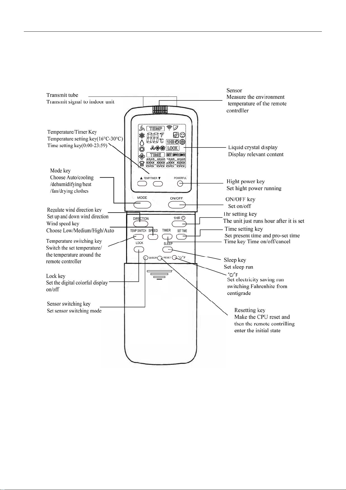
1.1 Remote controller
- 3 -
Page 4
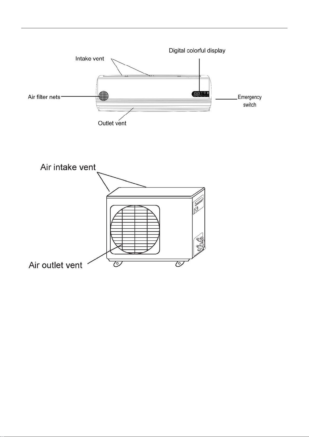
1.2 Indoor panel
1.3 Outdoor panel
Shinco Service Manual
- 4 -
Page 5
Shinco Service Manual
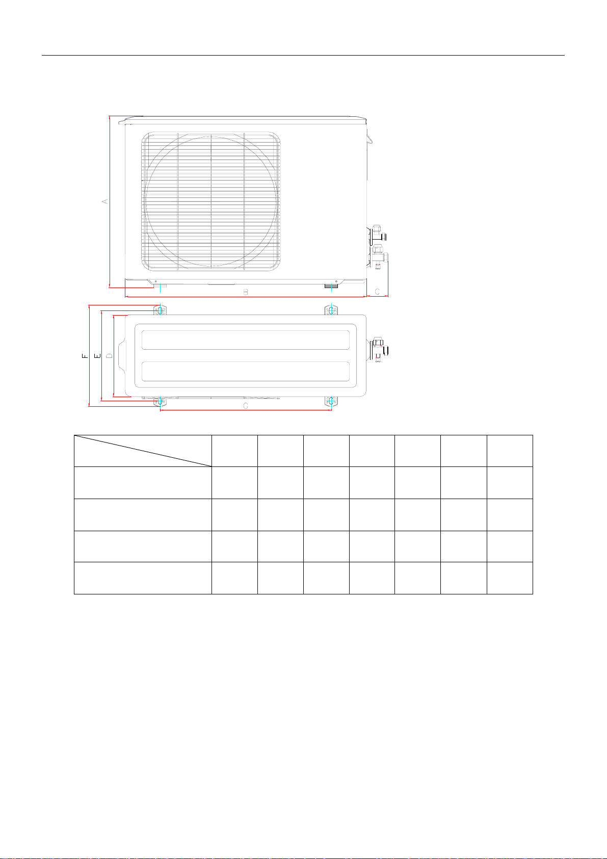
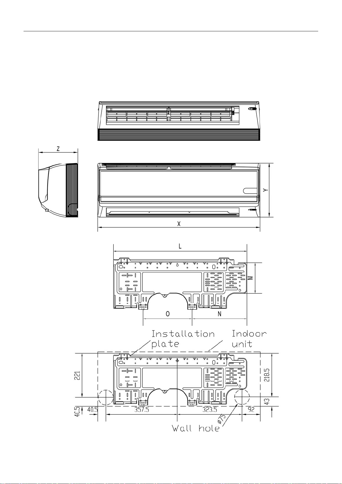
2. Outline Dimension of Indoor and Outdoor Units
2.1. Outdoor unit
MODEL
KFR-25GWZ/BM
SIZE mm
A B C D E F G
542 762 58 257 285 321 540
KFR-35GWZ/BM
542 762 58 257 285 321 540
KFR-50GWZ/BM
656 865 52 307 339.5 372 633
KFR-70GWZ/BM
840 950 60 352 388 425 582
- 5 -
Page 6
Shinco Service Manual
2.2 Indoor unit
Unit:mm
KFR-25GWZ/BM
KFR-35GWZ/BM
- 6 -
Page 7
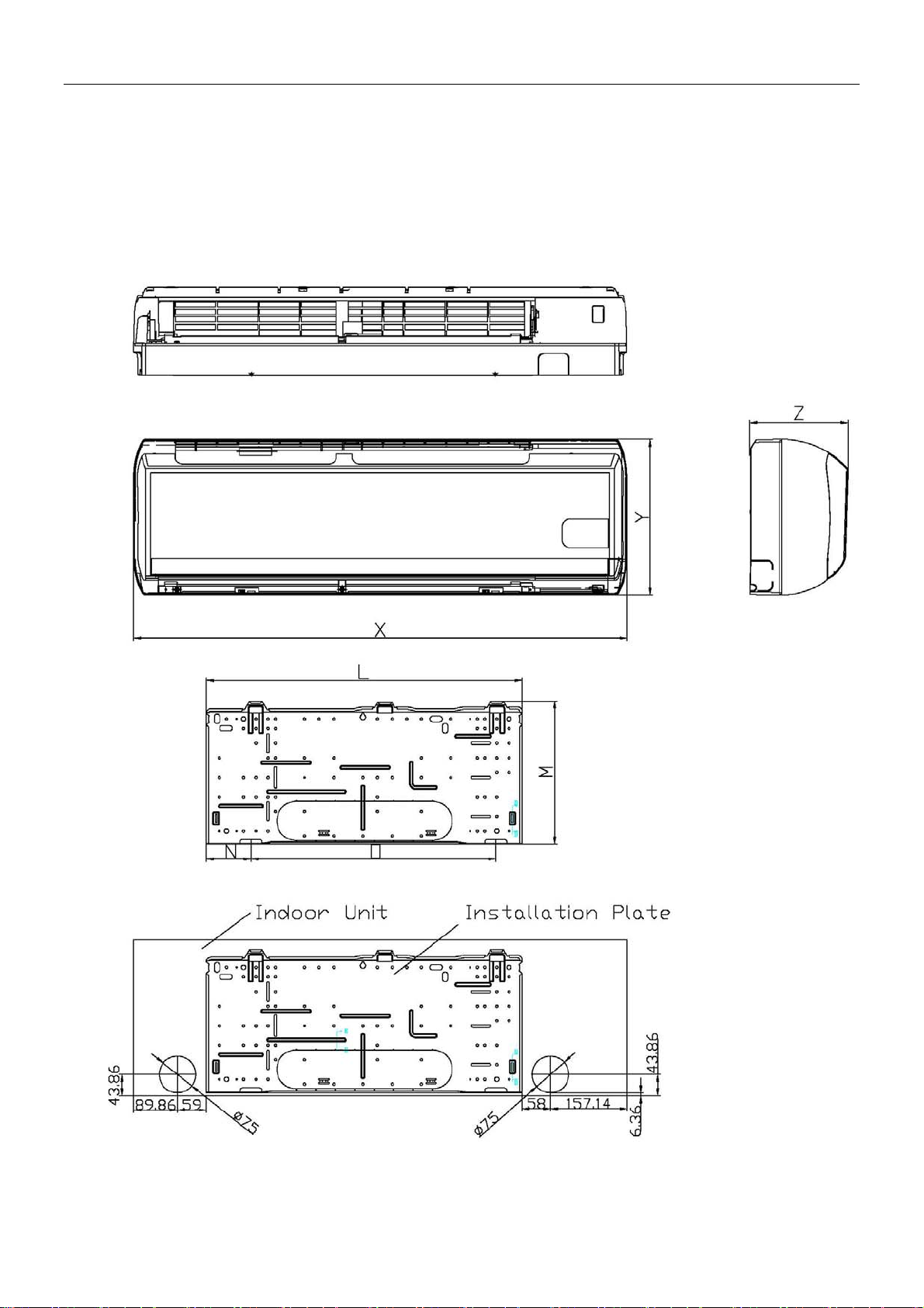
KFR-50GWZ/BM
Shinco Service Manual
- 7 -
Page 8
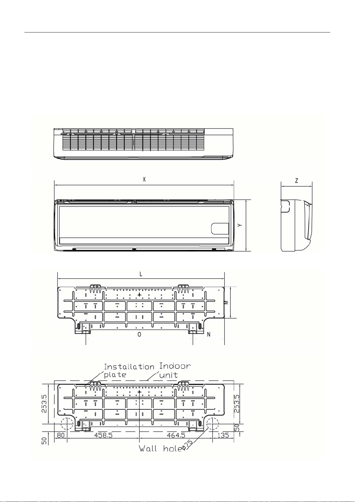
KFR-70GWZ/BM
Shinco Service Manual
- 8 -
Page 9
MODEL
SIZE mm
Shinco Service Manual
X Y Z L M N O
KFR-25GWZ/BM
KFR-35GWZ/BM
KFR-50GWZ/BM
KFR-70GWZ/BM
814 272 197 604 255 55 498
814 272 197 604 255 55 498
1013 323 198 648 295 57 502
1138 323 212 1055 312 180 679
3. Specification
Product type
Product
Number
Indoor
Outdoor bem25127610/W6 bem35127610/W6 bem50127603/W18 bem70127603/W13
Style
Compressor
Refrigerant R410A(pre-charged) R410A(pre-charged) R410A(pre-charged) R410A(pre-charged)
Cooling
Capacity
Heating
Capacity
Application
Area
Power Supply 230v/60Hz 230v/60Hz 230v/60Hz 230v/60Hz
Input Power
Input Current 3.4A(cool)/3.9A(heat) 4.9A(cool)/5.3A(heat) 7.6A(cool)/7.8A(heat) 10.4A(cool)/11.1A(heat)
SEER 13.8 13.6 14.5 13.3
HSPF 7.8 7.7 7.8 7.9
Sound Level 40dB(A)/54dB(A) 42dB(A)/55dB(A) 50dB(A)/58dB(A) 55dB(A)/62dB(A)
Dehumidify
Capacity(l/h)
Min Operating
Temp
Control System
Net
weight(Kg/lbs)
Dimensions(m
m/inches)
Line Set
Connection
Certificates ETL ETL ETL ETL
9000BTU 12000BTU 18000BTU 24000BTU
10400BTU 13650BTU 19100BTU 27000BTU
-7 -7 -7 -7
KFR-25GWZ/BM KFR-35GWZ/BM KFR-50GWZ/BM
bem25117610/G33 bem35117610/G33 bem50117603/G36 bem70117603/G37
Ductless mini split AC
system(heat pump)
Toshiba(rotary type DC
INVERTER)
10~18 ㎡ 16~24 ㎡
765W(cool)/880W(hea
t)
Ductless mini split AC
system(heat pump)
Toshiba(rotary type DC
INVERTER)
1075W(cool)/1160W(h
eat)
Ductless mini split AC
system(heat pump)
Panasonic(rotary type
DC INVERTER)
20~34 ㎡
1670W(cool)/1720W(he
at)
KFR-70GWZ/BM
Ductless mini split AC
system(heat pump)
Panasonic(rotary type
DC INVERTER)
32~47 ㎡
2400W(cool)/2550W(he
at)
0.85 1.5 1.7 2.1
Digital Multifunction
infrared Remote control
with indoor unit dynamic
digital LED display
11kg/24lbs(in),
40kg/88lbs(out)
814×192×272mm
3
2×7.6×
×
257×542mm
762
30
×
10.1×21.3inches(out)
10.7inches(in)
Digital Multifunction
infrared Remote control
with indoor unit dynamic
digital LCD display
11kg/24lbs(in),
43kg/95lbs(out)
814×192×272mm
32
×
7.6×10.7inches(in)
×
257×542mm
762
30
×
10.1×21.3inches(out)
Digital Multifunction
infrared Remote control
with indoor unit dynamic
digital LCD display
16kg/35lbs(in),51kg/112
lbs(out)
1013×198×323mm
39.9
865
34
×
7.8×12.7inches(in)
×
307×656mm
×12×
25.8inches(out)
Digital Multifunction
infrared Remote control
with indoor unit dynamic
digital LCD display
17kg/37lbs(in),68kg/150
lbs(out)
1138
44.8
950
37.4
×
212×323mm/
×
8.3×12.7inches(in)
×
352×840mm
×
13.8×33inches(out)
3 m connecting pipe 3 m connecting pipe 4 m connecting pipe 4 m connecting pipe
- 9 -
Page 10
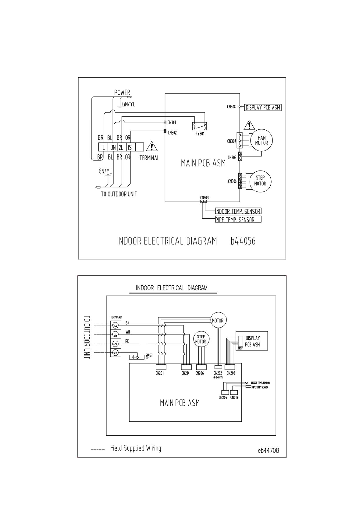
4. Wiring Diagram
4.1 Indoor unit Wiring diagram
KFR-25GWZ/BM
Shinco Service Manual
KFR-35GWZ/BM
- 10 -
Page 11
KFR-50GWZ/BM
Shinco Service Manual
KFR-70GWZ/BM
- 11 -
Page 12
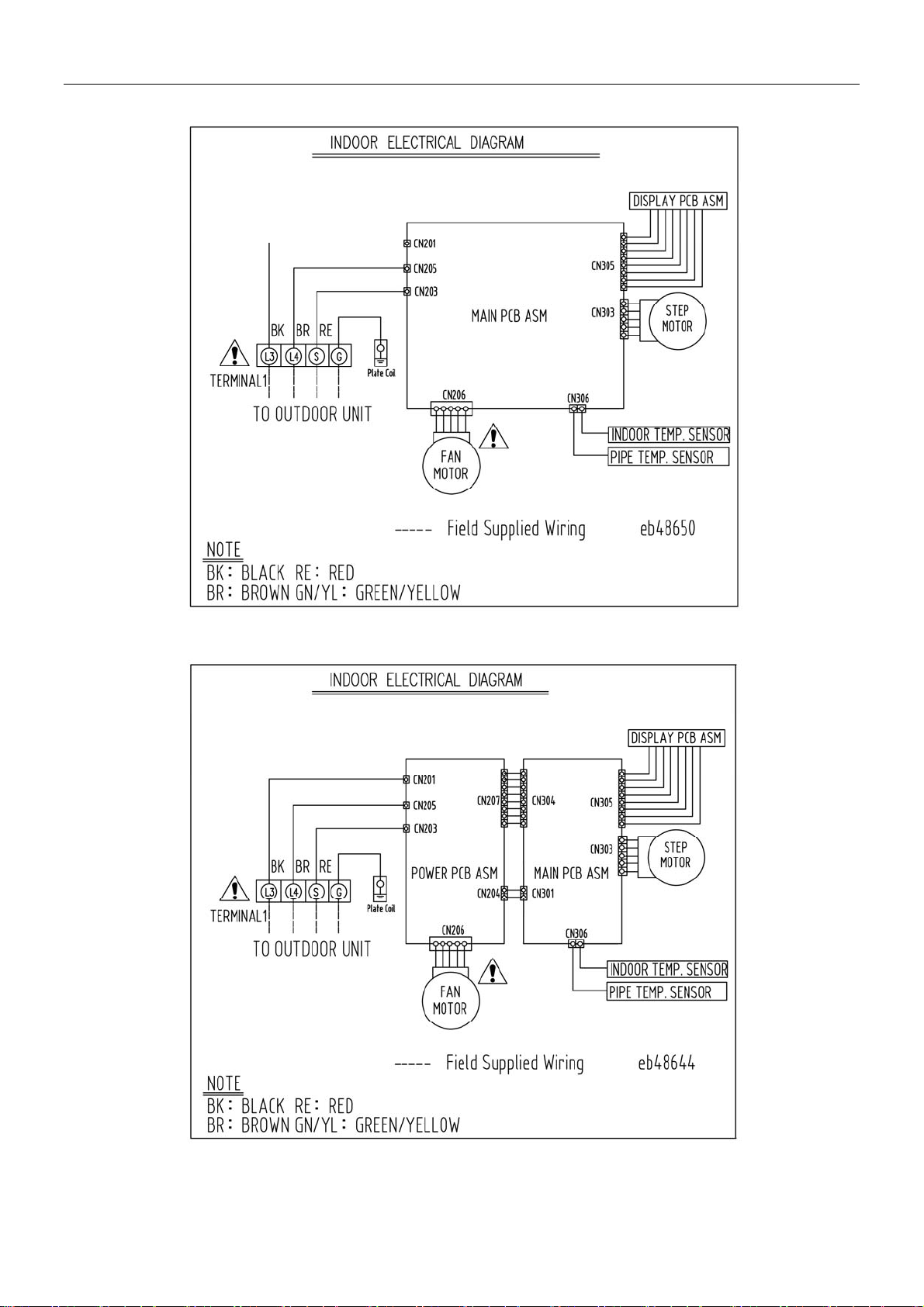
4.2 Outdoor unit Wiring diagram
KFR-25GWZ/BM
Shinco Service Manual
KFR-35GWZ/BM
- 12 -
Page 13
KFR-50GWZ/BM
Shinco Service Manual
KFR-70GWZ/BM
- 13 -
Page 14
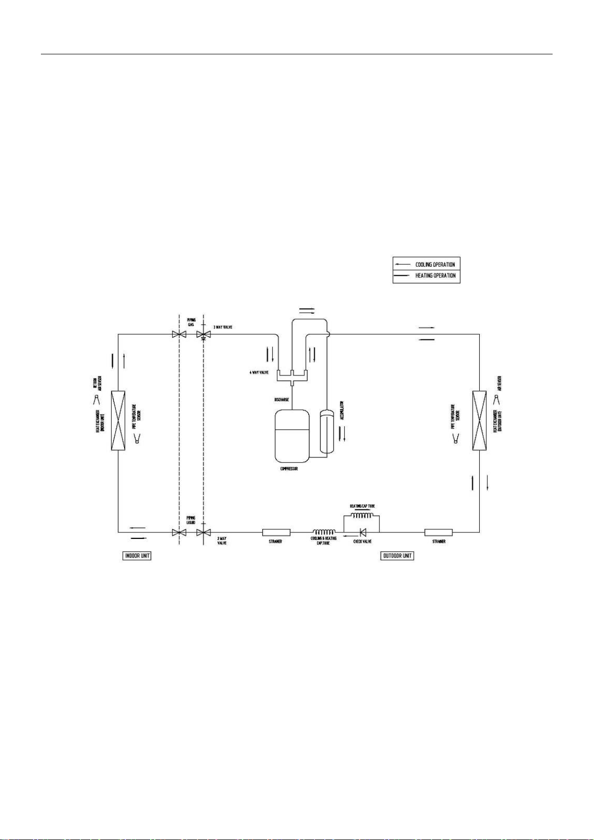
5. Refrigerant system diagram
Shinco Service Manual
- 14 -
Page 15
Shinco Service Manual
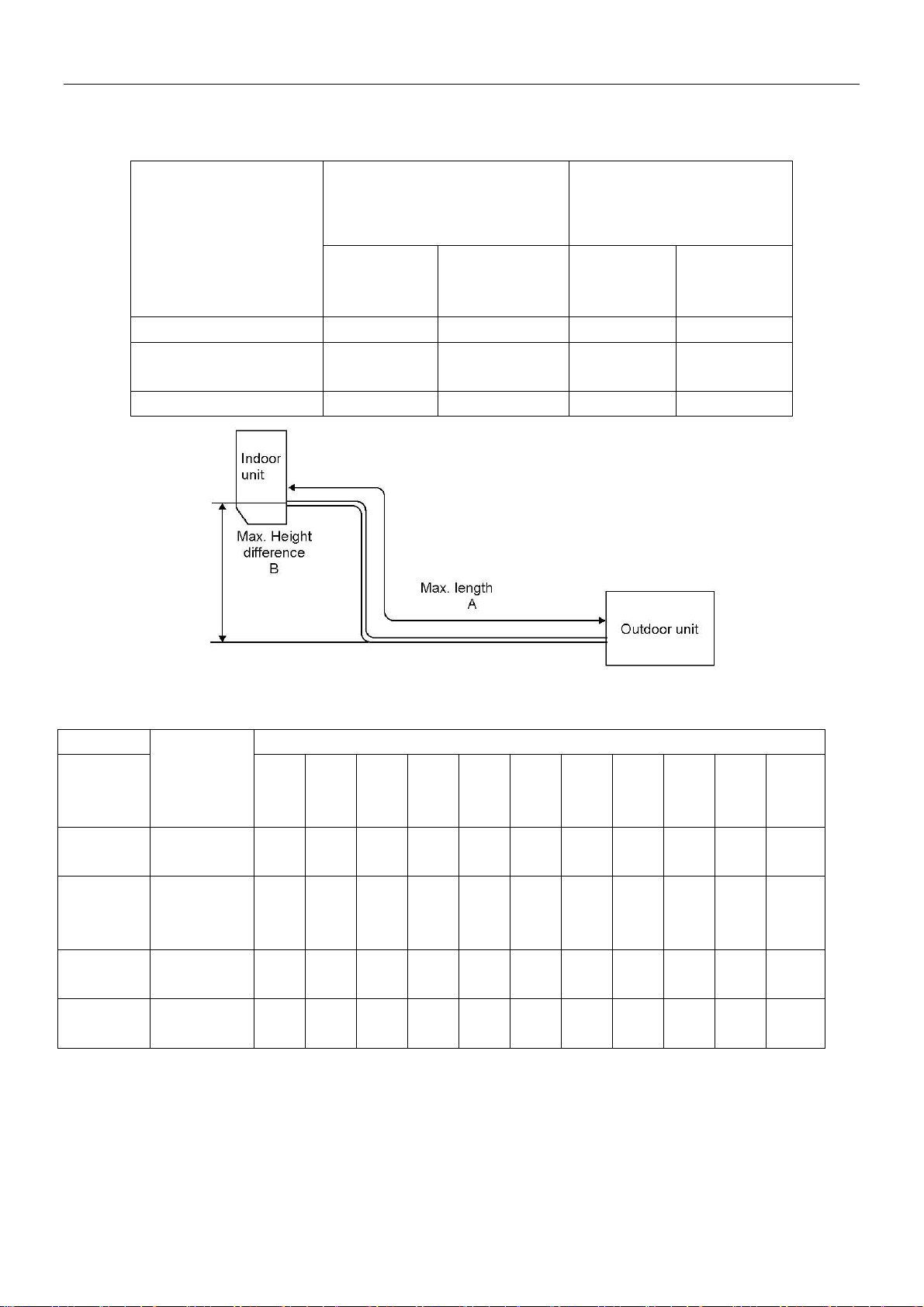
6. Max. refrigerant piping length and max. height difference
6.1 Piping length and height difference
REFRIGERANT PIPING:M PIPING SIZE O.D:mm MODEL
Max. length Max. Height
KFR-25GWZ/BM 15 5 9.52 6.35
KFR-35GWZ/BM
15 5 12.7 6.35
KFR-50GWZ/BM
KFR-70GWZ/BM 15 5 9.52 12.88
6.2 Additional refrigerant Charge (R410A:g)
Gas Liquid
difference
Model Refrigerant piping length(one way)
Outdoor
unit
5m 6m 7m 8m 9m 10m 11m 12m 13m 14m 15m
precharge
d(G)
KFR-25GW
840 0 20 40 60 80 100 120 140 160 180 200
Z/BM
KFR-35GW
1130 0 30 60 90 120 150 180 210 240 270 300
Z/BM
KFR-50GW
1300 0 30 60 90 120 150 180 210 240 270 300
Z/BM
KFR-70GW
1900 0 50 100 150 200 250 300 350 400 450 500
Z/BM
- 15 -
Page 16
Shinco Service Manual
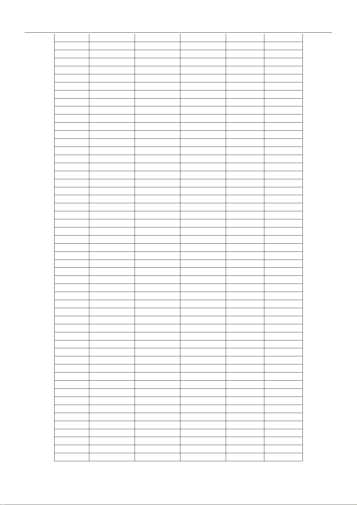
7. Sensor Resistance Table
7.1 KFR-25GWZ/BM、KFR-35GWZ/BM Sensor Resistance Table
7.1.1 indoor air sensor、indoor pipe sensor、outdoor air sensor、outdoor pipe sensor
R-T datasheet 10K±0.5% ;3976K±0.5%,B(25/85)=3976K±0.5% R-T datasheet
Temp.(℃) R(KΩ) Temp.(℃) R(KΩ) Temp.(℃)R(KΩ) Temp.(℃) R(KΩ)
-30
-29
-28
-27
-26
-25
-24
-23
-22
-21
-20
-19
-18
-17
-16
-15
-14
-13
-12
-11
-10
-9
-8
-7
-6
-5
-4
-3
-2
-1
0
1
2
3
180.719
169.891
159.763
150.289
141.422
133.124
125.355
118.079
111.264
104.879
98.895
93.284
88.023
83.089
78.458
74.112
70.032
66.200
62.599
59.216
56.035
53.044
50.231
47.583
45.091
42.744
40.534
38.451
36.487
34.636
32.890
31.242
29.687
28.219
4
5
6
7
8
9
10
11
12
13
14
15
16
17
18
19
20
21
22
23
24
25
26
27
28
29
30
31
32
33
34
35
36
37
26.832
25.522
24.284
23.113
22.006
20.958
19.967
19.028
18.139
17.297
16.499
15.742
15.024
14.344
13.698
13.085
12.503
11.950
11.425
10.926
10.451
10.000
9.571
9.162
8.773
8.403
8.051
7.715
7.395
7.090
6.799
6.522
6.257
6.005
38
39
40
41
42
43
44
45
46
47
48
49
50
51
52
53
54
55
56
57
58
59
60
61
62
63
64
65
66
67
68
69
70
71
5.764
5.534
5.315
5.105
4.905
4.713
4.530
4.355
4.188
4.028
3.875
3.728
3.588
3.454
3.325
3.202
3.084
2.971
2.863
2.760
2.660
2.565
2.474
2.386
2.302
2.221
2.144
2.070
1.998
1.930
1.864
1.801
1.741
1.683
72
73
74
75
76
77
78
79
80
81
82
83
84
85
86
87
88
89
90
91
92
93
94
95
96
97
98
99
100
101
102
103
104
105
1.627
1.573
1.522
1.472
1.425
1.379
1.335
1.293
1.252
1.213
1.176
1.140
1.105
1.072
1.040
1.009
0.980
0.951
0.924
0.897
0.872
0.848
0.824
0.802
0.780
0.760
0.740
0.720
0.702
0.684
0.667
0.651
0.635
0.620
- 16 -
Page 17
Shinco Service Manual
7.1.2 outdoor discharge pipe R(0)=187.25K±6.3% ;B(0/100)=3979K±1% R-T datasheet
Temp.(℃) R(min) (KΩ) R(cent) (KΩ) R(max) (KΩ)
-20 488.35 526.61 565.60 -7.3% 7.4%
-19 461.94 497.84 534.41 -7.2% 7.3%
-18 437.15 470.87 505.17 -7.2% 7.3%
-17 413.89 445.57 477.76 -7.1% 7.2%
-16 392.05 421.83 462.06 -7.1% 9.5%
-15 371.54 399.54 427.94 -7.0% 7.1%
-14 352.27 378.61 405.31 -7.0% 7.1%
-13 334.16 358.96 384.06 -6.9% 7.0%
-12 317.13 340.48 364.10 -6.9% 6.9%
-11 301.11 323.11 345.34 -6.8% 6.9%
-10 286.03 306.77 327.71 -6.8% 6.8%
-9 271.83 291.40 311.13 -6.7% 6.8%
-8 258.46 276.92 295.52 -6.7% 6.7%
-7 245.86 263.29 280.83 -6.6% 6.7%
-6 233.98 250.44 266.99 -6.6% 6.6%
-5 222.78 238.33 253.96 -6.5% 6.6%
-4 212.20 226.91 241.67 -6.5% 6.5%
-3 202.22 216.13 230.07 -6.4% 6.4%
-2 192.79 205.95 219.13 -6.4% 6.4%
-1 183.88 196.34 208.80 -6.3% 6.3%
0 175.45 187.25 199.05 -6.3% 6.3%
1 167.33 178.66 190.00 -6.3% 6.3%
2 159.64 170.53 181.45 -6.4% 6.4%
3 152.37 162.84 173.34 -6.4% 6.4%
4 145.49 155.56 165.67 -6.5% 6.5%
5 138.97 148.66 158.39 -6.5% 6.5%
6 132.80 142.12 151.49 -6.6% 6.6%
7 126.95 135.92 144.94 -6.6% 6.6%
8 121.40 130.03 138.73 -6.6% 6.7%
9 116.13 124.45 132.83 -6.7% 6.7%
10 111.13 119.14 127.22 -6.7% 6.8%
11 106.38 114.10 121.89 -6.8% 6.8%
12 101.87 109.31 116.82 -6.8% 6.9%
13 97.585 104.75 112.00 -6.8% 6.9%
14 93.506 100.42 107.41 -6.9% 7.0%
15 89.625 96.289 103.04 -6.9% 7.0%
16 85.930 92.358 98.873 -7.0% 7.1%
17 82.411 88.612 94.902 -7.0% 7.1%
18 79.058 85.042 91.116 -7.0% 7.1%
19 75.861 81.637 87.503 -7.1% 7.2%
20 72.813 78.388 84.055 -7.1% 7.2%
21 69.904 75.287 80.768 -7.1% 7.3%
22 67.128 72.326 77.618 -7.2% 7.3%
23 64.477 69.498 74.612 -7.2% 7.4%
24 61.945 66.795 71.738 -7.3% 7.4%
25 59.525 64.210 68.990 -7.3% 7.4%
26 57.211 61.739 66.360 -7.3% 7.5%
27 54.998 59.373 63.843 -7.4% 7.5%
28 52.880 57.110 61.433 -7.4% 7.6%
29 50.853 54.942 59.124 -7.4% 7.6%
30 48.913 52.866 56.911 -7.5% 7.7%
ΔR(min) ΔR(max)
- 17 -
Page 18
Shinco Service Manual
31 47.054 50.876 54.791 -7.5% 7.7%
32 45.273 48.939 52.757 -7.5% 7.8%
33 43.565 47.140 50.806 -7.6% 7.8%
34 41.928 45.386 48.934 -7.6% 7.8%
35 40.358 43.703 47.137 -7.7% 7.9%
36 38.852 42.087 45.412 -7.7% 7.9%
37 37.408 40.536 43.755 -7.7% 7.9%
38 36.018 39.047 42.163 -7.8% 8.0%
39 34.685 37.616 40.632 -7.8% 8.0%
40 33.404 36.240 39.162 -7.8% 8.1%
41 32.174 34.919 37.747 -7.9% 8.1%
42 30.991 33.648 36.387 -7.9% 8.1%
43 29.855 32.426 35.078 -7.9% 8.2%
44 28.761 31.250 33.819 -8.0% 8.2%
45 27.710 30.119 32.606 -8.0% 8.3%
46 26.699 29.030 31.439 -8.0% 8.3%
47 25.725 27.982 30.315 -8.1% 8.3%
48 24.788 26.973 29.233 -8.1% 8.4%
49 23.887 26.001 28.190 -8.1% 8.4%
50 23.018 25.065 27.185 -8.2% 8.5%
51 22.182 24.163 26.217 -8.2% 8.5%
52 21.377 23.295 25.284 -8.2% 8.5%
53 20.601 22.457 24.384 -8.3% 8.6%
54 19.854 21.650 23.516 -8.3% 8.6%
55 19.133 20.873 22.680 -8.3% 8.7%
56 18.439 20.123 21.873 -8.4% 8.7%
57 17.770 19.399 21.094 -8.4% 8.7%
58 17.125 18.702 20.343 -8.4% 8.8%
59 16.503 18.029 19.618 -8.5% 8.8%
60 15.903 17.380 18.920 -8.5% 8.9%
61 15.324 16.754 18.245 -8.5% 8.9%
62 14.766 16.150 17.594 -8.6% 8.9%
63 14.228 15.568 16.965 -8.6% 9.0%
64 13.709 15.005 16.358 -8.6% 9.0%
65 13.209 14.463 15.772 -8.7% 9.1%
66 12.726 13.939 15.207 -8.7% 9.1%
67 12.260 13.433 14.681 -8.7% 9.3%
68 11.810 12.946 14.134 -8.8% 9.2%
69 11.376 12.475 13.650 -8.8% 9.4%
70 10.958 12.020 13.133 -8.8% 9.3%
71 10.554 11.581 12.658 -8.9% 9.3%
72 10.164 11.158 12.200 -8.9% 9.3%
73 9.7880 10.749 11.757 -8.9% 9.4%
74 9.4251 10.354 11.330 -9.0% 9.4%
75 9.0749 9.9733 10.917 -9.0% 9.5%
76 8.7370 9.6055 10.518 -9.0% 9.5%
77 8.4109 9.2505 10.134 -9.1% 9.6%
78 8.0962 8.9078 9.7618 -9.1% 9.6%
79 7.7926 8.5770 9.4028 -9.1% 9.6%
80 7.4997 8.2577 9.0562 -9.2% 9.7%
81 7.2170 7.9495 8.7215 -9.2% 9.7%
82 6.9443 7.6520 8.3983 -9.2% 9.8%
83 6.6812 7.3649 8.0883 -9.3% 9.8%
- 18 -
Page 19
Shinco Service Manual
84 6.4273 7.0878 7.7850 -9.3% 9.8%
85 6.1825 6.8204 7.4942 -9.4% 9.9%
86 5.9462 6.5623 7.2135 -9.4% 9.9%
87 5.7184 6.3133 6.9424 -9.4% 10.0%
88 5.4987 6.0731 6.6808 -9.5% 10.0%
89 5.2867 5.8413 6.4284 -9.5% 10.1%
90 5.0827 5.6177 6.1847 -9.5% 10.1%
91 4.8853 5.4018 5.9495 -9.6% 10.1%
92 4.6953 5.1939 5.7226 -9.6% 10.2%
93 4.5121 4.9932 5.5037 -9.6% 10.2%
94 4.3355 4.7997 5.2925 -9.7% 10.3%
95 4.1653 4.6131 5.0840 -9.7% 10.2%
96 4.0012 4.4331 4.8922 -9.7% 10.4%
97 3.8431 4.2596 4.7026 -9.8% 10.4%
98 3.6908 4.0924 4.5198 -9.8% 10.4%
99 3.5440 3.9312 4.3435 -9.8% 10.5%
100 3.4025 3.7759 4.1735 -9.9% 10.5%
101 3.2663 3.6262 4.0097 -9.9% 10.6%
102 3.1351 3.4819 3.8517 -10.0% 10.6%
103 3.0087 3.3429 3.6995 -10.0% 10.7%
104 2.8870 3.2090 3.5528 -10.0% 10.7%
105 2.7699 3.0801 3.4114 -10.1% 10.8%
106 2.6571 2.9559 3.2720 -10.1% 10.7%
107 2.5485 2.8363 3.1440 -10.1% 10.8%
108 2.4441 2.7211 3.0176 -10.2% 10.9%
109 2.3435 2.6103 2.8959 -10.2% 10.9%
110 2.2468 2.5036 2.7787 -10.3% 11.0%
111 2.1537 2.4009 2.6658 -10.3% 11.0%
112 2.0642 2.3021 2.5572 -10.3% 11.1%
113 1.9781 2.2070 2.4526 -10.4% 11.1%
114 1.8954 2.1155 2.3519 -10.4% 11.2%
115 1.8158 2.0276 2.2551 -10.4% 11.2%
116 1.7393 1.9430 2.1619 -10.5% 11.3%
117 1.6657 1.8616 2.0723 -10.5% 11.3%
118 1.5951 1.7834 1.9861 -10.6% 11.4%
119 1.5272 1.7082 1.9032 -10.6% 11.4%
120 1.4619 1.6359 1.8234 -10.6% 11.5%
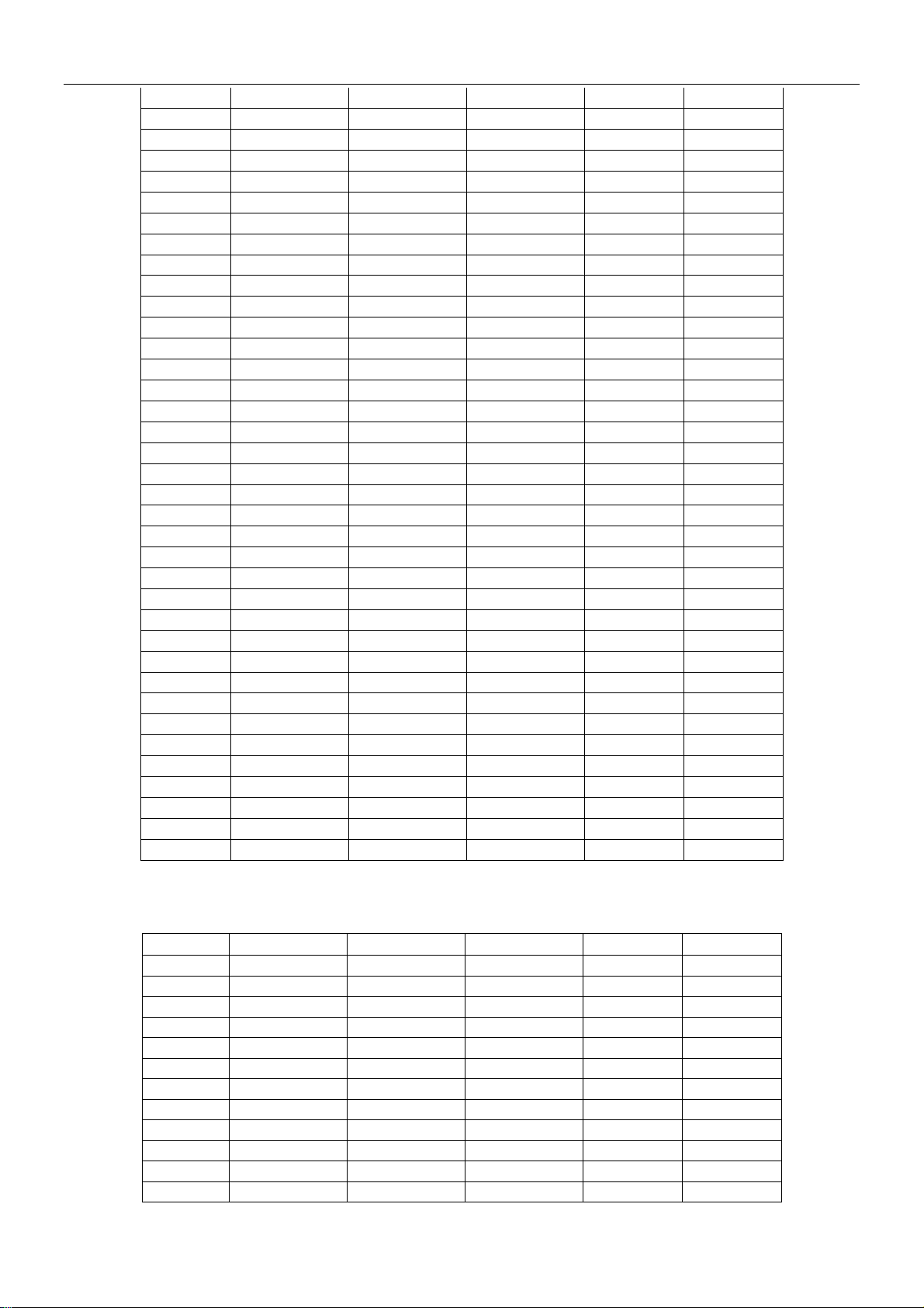
7.2 KFR-50GWZ/BM、KFR-70GWZ/BM Sensor Resistance Table
7.2.1 indoor air sensor R(25)=5K±2% ;B(25/50)=3950K±2% R-T datasheet
Temp.(℃) R(min) (KΩ) R(cent) (KΩ) R(max) (KΩ)
-20 44.23 47.70 51.40 -7.3% 7.8%
-19 41.82 45.05 48.49 -7.2% 7.6%
-18 39.55 42.56 45.76 -7.1% 7.5%
-17 37.43 40.23 43.20 -7.0% 7.4%
-16 35.43 38.03 40.80 -6.9% 7.3%
-15 33.54 35.97 38.54 -6.8% 7.1%
-14 31.77 34.04 36.43 -6.7% 7.0%
-13 30.11 32.22 34.44 -6.5% 6.9%
-12 28.54 30.50 32.57 -6.4% 6.8%
-11 27.06 28.89 30.82 -6.3% 6.7%
-10 25.66 27.37 29.17 -6.2% 6.6%
-9 24.35 25.94 27.61 -6.1% 6.4%
ΔR(min) ΔR(max)
- 19 -
Page 20
Shinco Service Manual
-8 23.11 24.59 26.15 -6.0% 6.3%
-7 21.94 23.33 24.78 -5.9% 6.2%
-6 20.84 22.13 23.48 -5.8% 6.1%
-5 19.79 21.00 22.26 -5.7% 6.0%
-4 18.81 19.94 21.11 -5.6% 5.9%
-3 17.88 18.93 20.03 -5.5% 5.8%
-2 17.00 17.98 19.00 -5.5% 5.7%
-1 16.17 17.09 18.04 -5.4% 5.6%
0 15.39 16.24 17.13 -5.3% 5.5%
1 14.64 15.44 16.27 -5.2% 5.3%
2 13.94 14.69 15.46 -5.1% 5.2%
3 13.28 13.97 14.69 -5.0% 5.1%
4 12.65 13.30 13.96 -4.9% 5.0%
5 12.05 12.66 13.28 -4.8% 4.9%
6 11.49 12.05 12.63 -4.7% 4.8%
7 10.95 11.48 12.02 -4.6% 4.7%
8 10.44 10.93 11.44 -4.5% 4.6%
9 9.961 10.42 10.89 -4.4% 4.5%
10 9.504 9.934 10.37 -4.3% 4.4%
11 9.071 9.472 9.881 -4.2% 4.3%
12 8.660 9.034 9.416 -4.1% 4.2%
13 8.270 8.619 8.974 -4.1% 4.1%
14 7.899 8.225 8.556 -4.0% 4.0%
15 7.547 7.851 8.159 -3.9% 3.9%
16 7.212 7.496 7.783 -3.8% 3.8%
17 6.894 7.159 7.427 -3.7% 3.7%
18 6.592 6.839 7.088 -3.6% 3.6%
19 6.305 6.534 6.767 -3.5% 3.6%
20 6.031 6.245 6.462 -3.4% 3.5%
21 5.771 5.971 6.172 -3.3% 3.4%
22 5.524 5.710 5.897 -3.3% 3.3%
23 5.288 5.461 5.635 -3.2% 3.2%
24 5.064 5.225 5.386 -3.1% 3.1%
25 4.850 5.000 5.150 -3.0% 3.0%
26 4.638 4.786 4.934 -3.1% 3.1%
27 4.437 4.582 4.728 -3.2% 3.2%
28 4.245 4.388 4.532 -3.3% 3.3%
29 4.063 4.203 4.344 -3.3% 3.4%
30 3.890 4.027 4.166 -3.4% 3.4%
31 3.724 3.859 3.996 -3.5% 3.5%
32 3.567 3.699 3.833 -3.6% 3.6%
33 3.417 3.547 3.679 -3.7% 3.7%
34 3.274 3.401 3.531 -3.7% 3.8%
35 3.138 3.263 3.389 -3.8% 3.9%
36 3.008 3.130 3.255 -3.9% 4.0%
37 2.884 3.004 3.126 -4.0% 4.1%
38 2.766 2.883 3.003 -4.1% 4.1%
39 2.654 2.768 2.885 -4.1% 4.2%
40 2.546 2.658 2.773 -4.2% 4.3%
41 2.444 2.553 2.665 -4.3% 4.4%
42 2.346 2.453 2.563 -4.4% 4.5%
43 2.252 2.357 2.464 -4.4% 4.6%
44 2.163 2.265 2.370 -4.5% 4.6%
- 20 -
Page 21

Shinco Service Manual
45 2.077 2.178 2.280 -4.6% 4.7%
46 1.996 2.094 2.194 -4.7% 4.8%
47 1.918 2.014 2.112 -4.7% 4.9%
48 1.843 1.937 2.033 -4.8% 5.0%
49 1.772 1.863 1.958 -4.9% 5.1%
50 1.704 1.793 1.885 -5.0% 5.1%
51 1.639 1.726 1.816 -5.0% 5.2%
52 1.577 1.662 1.749 -5.1% 5.3%
53 1.517 1.600 1.686 -5.2% 5.4%
54 1.460 1.541 1.625 -5.3% 5.5%
55 1.405 1.484 1.566 -5.3% 5.5%
56 1.353 1.430 1.510 -5.4% 5.6%
57 1.303 1.378 1.456 -5.5% 5.7%
58 1.255 1.328 1.405 -5.5% 5.8%
59 1.209 1.280 1.355 -5.6% 5.8%
60 1.164 1.235 1.308 -5.7% 5.9%
61 1.122 1.191 1.262 -5.7% 6.0%
62 1.082 1.148 1.218 -5.8% 6.1%
63 1.043 1.108 1.176 -5.9% 6.2%
64 1.006 1.069 1.136 -5.9% 6.2%
65 0.9698 1.032 1.097 -6.0% 6.3%
66 0.9355 0.9960 1.060 -6.1% 6.4%
67 0.9025 0.9616 1.024 -6.1% 6.5%
68 0.8709 0.9286 0.9892 -6.2% 6.5%
69 0.8406 0.8969 0.9561 -6.3% 6.6%
70 0.8115 0.8664 0.9243 -6.3% 6.7%
71 0.7835 0.8372 0.8936 -6.4% 6.7%
72 0.7567 0.8090 0.8642 -6.5% 6.8%
73 0.7309 0.7819 0.8359 -6.5% 6.9%
74 0.7061 0.7559 0.8086 -6.6% 7.0%
75 0.6822 0.7309 0.7824 -6.7% 7.0%
76 0.6593 0.7068 0.7571 -6.7% 7.1%
77 0.6373 0.6837 0.7328 -6.8% 7.2%
78 0.6161 0.6614 0.7094 -6.8% 7.3%
79 0.5958 0.6400 0.6868 -6.9% 7.3%
80 0.5762 0.6193 0.6651 -7.0% 7.4%
81 0.5573 0.5995 0.6442 -7.0% 7.5%
82 0.5392 0.5804 0.6241 -7.1% 7.5%
83 0.5218 0.5619 0.6047 -7.1% 7.6%
84 0.5050 0.5442 0.5859 -7.2% 7.7%
85 0.4888 0.5271 0.5679 -7.3% 7.7%
86 0.4732 0.5106 0.5505 -7.3% 7.8%
87 0.4582 0.4948 0.5337 -7.4% 7.9%
88 0.4438 0.4795 0.5176 -7.4% 7.9%
89 0.4299 0.4647 0.5020 -7.5% 8.0%
90 0.4165 0.4505 0.4869 -7.6% 8.1%
91 0.4036 0.4368 0.4724 -7.6% 8.1%
92 0.3911 0.4236 0.4584 -7.7% 8.2%
93 0.3791 0.4109 0.4449 -7.7% 8.3%
94 0.3676 0.3986 0.4318 -7.8% 8.3%
95 0.3564 0.3867 0.4192 -7.8% 8.4%
96 0.3456 0.3753 0.4071 -7.9% 8.5%
97 0.3353 0.3642 0.3953 -8.0% 8.5%
- 21 -
Page 22
Shinco Service Manual
98 0.3253 0.3536 0.3840 -8.0% 8.6%
99 0.3156 0.3433 0.3730 -8.1% 8.7%
100 0.3063 0.3333 0.3624 -8.1% 8.7%
101 0.2973 0.3237 0.3522 -8.2% 8.8%
102 0.2886 0.3144 0.3423 -8.2% 8.9%
103 0.2802 0.3055 0.3327 -8.3% 8.9%
104 0.2721 0.2968 0.3235 -8.3% 9.0%
105 0.2643 0.2885 0.3146 -8.4% 9.0%
106 0.2568 0.2804 0.3059 -8.4% 9.1%
107 0.2495 0.2726 0.2976 -8.5% 9.2%
108 0.2424 0.2650 0.2895 -8.5% 9.2%
109 0.2356 0.2577 0.2817 -8.6% 9.3%
110 0.2290 0.2507 0.2741 -8.6% 9.4%
111 0.2227 0.2438 0.2668 -8.7% 9.4%
112 0.2165 0.2372 0.2597 -8.7% 9.5%
113 0.2106 0.2309 0.2529 -8.8% 9.5%
114 0.2048 0.2247 0.2462 -8.8% 9.6%
115 0.1993 0.2187 0.2398 -8.9% 9.7%
116 0.1939 0.2129 0.2336 -8.9% 9.7%
117 0.1887 0.2073 0.2276 -9.0% 9.8%
118 0.1837 0.2019 0.2217 -9.0% 9.8%
119 0.1788 0.1966 0.2161 -9.1% 9.9%
120 0.1741 0.1916 0.2106 -9.1% 9.9%
121 0.1695 0.1866 0.2053 -9.2% 10.0%
122 0.1651 0.1819 0.2002 -9.2% 10.1%
123 0.1608 0.1772 0.1952 -9.3% 10.1%
124 0.1567 0.1728 0.1903 -9.3% 10.2%
125 0.1527 0.1684 0.1857 -9.4% 10.2%
126 0.1488 0.1642 0.1811 -9.4% 10.3%
127 0.1450 0.1602 0.1767 -9.5% 10.3%
128 0.1414 0.1562 0.1725 -9.5% 10.4%
129 0.1379 0.1524 0.1683 -9.5% 10.4%
130 0.1344 0.1487 0.1643 -9.6% 10.5%
131 0.1311 0.1451 0.1604 -9.6% 10.6%
132 0.1279 0.1416 0.1566 -9.7% 10.6%
133 0.1248 0.1382 0.1530 -9.7% 10.7%
134 0.1218 0.1349 0.1494 -9.8% 10.7%
135 0.1188 0.1318 0.1459 -9.8% 10.8%
136 0.1160 0.1287 0.1426 -9.8% 10.8%
137 0.1132 0.1257 0.1393 -9.9% 10.9%
138 0.1106 0.1228 0.1362 -9.9% 10.9%
139 0.1080 0.1199 0.1331 -10.0% 11.0%
140 0.1055 0.1172 0.1301 -10.0% 11.0%
141 0.1030 0.1145 0.1272 -10.1% 11.1%
142 0.1007 0.1120 0.1244 -10.1% 11.1%
143 0.0984 0.1095 0.1217 -10.1% 11.2%
144 0.0961 0.1070 0.1190 -10.2% 11.2%
145 0.0940 0.1047 0.1165 -10.2% 11.3%
146 0.0919 0.1024 0.1140 -10.3% 11.3%
147 0.0898 0.1001 0.1115 -10.3% 11.4%
148 0.0878 0.0980 0.1092 -10.3% 11.4%
149 0.0859 0.0959 0.1069 -10.4% 11.5%
150 0.0840 0.0938 0.1046 -10.4% 11.5%
- 22 -
Page 23
Shinco Service Manual
151 0.0822 0.0918 0.1025 -10.5% 11.6%
152 0.0805 0.0899 0.1003 -10.5% 11.6%
153 0.0787 0.0880 0.0983 -10.5% 11.7%
154 0.0771 0.0862 0.0963 -10.6% 11.7%
155 0.0755 0.0844 0.0943 -10.6% 11.8%
156 0.0739 0.0827 0.0924 -10.6% 11.8%
157 0.0724 0.0810 0.0906 -10.7% 11.9%
158 0.0709 0.0794 0.0888 -10.7% 11.9%
159 0.0694 0.0778 0.0871 -10.7% 11.9%
160 0.0680 0.0762 0.0854 -10.8% 12.0%
7.2.2 indoor pipe sensor R(0)=188.1K±4% ;B(0/50)3877K±3% R-T datasheet
Temp.(℃) R(min) (KΩ) R(cent) (KΩ) R(max) (KΩ)
-20
-19
-18
-17
-16
-15
-14
-13
-12
-11
-10
-9
-8
-7
-6
-5
-4
-3
-2
-1
0
1
2
3
4
5
6
7
8
9
10
11
12
13
14
15
16
17
18
510.22 548.83 589.42
482.84 518.50 555.89
457.10 490.02 524.47
432.88 463.28 495.02
410.09 438.16 467.39
388.64 414.55 441.47
368.44 392.35 417.14
349.41 371.47 394.30
331.47 351.83 372.84
314.56 333.34 352.67
298.61 315.93 333.72
283.56 299.53 315.89
269.36 284.07 299.11
255.95 269.50 283.32
243.28 255.77 268.46
231.32 242.81 254.46
220.01 230.58 241.27
209.31 219.03 228.84
199.20 208.13 217.11
189.63 197.83 206.06
180.58 188.10 195.62
171.49 178.90 186.34
162.91 170.20 177.54
154.80 161.98 169.21
147.14 154.19 161.32
139.91 146.82 153.83
133.06 139.85 146.74
126.59 133.24 140.01
120.47 126.98 133.62
114.68 121.05 127.57
109.20 115.42 121.81
104.00 110.09 116.35
99.085 105.03 111.16
94.425 100.23 106.23
90.008 95.680 101.55
85.822 91.355 97.091
81.851 87.249 92.855
78.085 83.349 88.825
74.511 79.643 84.992
- 23 -
ΔR(min) ΔR(max)
-7.0% 7.4%
-6.9% 7.2%
-6.7% 7.0%
-6.6% 6.9%
-6.4% 6.7%
-6.2% 6.5%
-6.1% 6.3%
-5.9% 6.1%
-5.8% 6.0%
-5.6% 5.8%
-5.5% 5.6%
-5.3% 5.5%
-5.2% 5.3%
-5.0% 5.1%
-4.9% 5.0%
-4.7% 4.8%
-4.6% 4.6%
-4.4% 4.5%
-4.3% 4.3%
-4.1% 4.2%
-4.0% 4.0%
-4.1% 4.2%
-4.3% 4.3%
-4.4% 4.5%
-4.6% 4.6%
-4.7% 4.8%
-4.9% 4.9%
-5.0% 5.1%
-5.1% 5.2%
-5.3% 5.4%
-5.4% 5.5%
-5.5% 5.7%
-5.7% 5.8%
-5.8% 6.0%
-5.9% 6.1%
-6.1% 6.3%
-6.2% 6.4%
-6.3% 6.6%
-6.4% 6.7%
Page 24

19
20
21
22
23
24
25
26
27
28
29
30
31
32
33
34
35
36
37
38
39
40
41
42
43
44
45
46
47
48
49
50
51
52
53
54
55
56
57
58
59
60
61
62
63
64
65
66
67
68
69
70
71
Shinco Service Manual
71.119 76.120 81.343
67.899 72.772 77.870
64.840 69.587 74.562
61.935 66.558 71.412
59.175 63.676 68.411
56.551 60.934 65.550
54.057 58.323 62.824
51.685 55.836 60.225
49.429 53.469 57.746
47.282 51.213 55.381
45.239 49.063 53.125
43.295 47.014 50.971
41.443 45.061 48.916
39.679 43.198 46.953
37.999 41.421 45.078
36.398 39.726 43.288
34.872 38.108 41.576
33.418 36.563 39.941
32.031 35.089 38.378
30.708 33.681 36.883
29.445 32.336 35.454
28.241 31.051 34.086
27.091 29.823 32.778
25.994 28.649 31.526
24.946 27.527 30.327
23.945 26.454 29.180
22.988 25.428 28.081
22.075 24.446 27.029
21.201 23.507 26.021
20.367 22.607 25.055
19.568 21.747 24.129
18.805 20.923 23.241
18.075 20.133 22.391
17.376 19.378 21.575
16.708 18.653 20.792
16.068 17.959 20.041
15.455 17.294 19.321
14.869 16.657 18.630
14.307 16.045 17.966
13.769 15.459 17.329
13.253 14.897 16.717
12.759 14.357 16.130
12.286 13.840 15.565
11.832 13.343 15.023
11.396 12.866 14.502
10.979 12.408 14.001
10.578 11.969 13.520
10.194 11.546 13.057
9.8257 11.141 12.612
9.4720 10.751 12.184
9.1324 10.377 11.772
8.8064 10.017 11.376
8.4934 9.6711 10.995
-6.6% 6.9%
-6.7% 7.0%
-6.8% 7.1%
-6.9% 7.3%
-7.1% 7.4%
-7.2% 7.6%
-7.3% 7.7%
-7.4% 7.9%
-7.6% 8.0%
-7.7% 8.1%
-7.8% 8.3%
-7.9% 8.4%
-8.0% 8.6%
-8.1% 8.7%
-8.3% 8.8%
-8.4% 9.0%
-8.5% 9.1%
-8.6% 9.2%
-8.7% 9.4%
-8.8% 9.5%
-8.9% 9.6%
-9.0% 9.8%
-9.2% 9.9%
-9.3% 10.0%
-9.4% 10.2%
-9.5% 10.3%
-9.6% 10.4%
-9.7% 10.6%
-9.8% 10.7%
-9.9% 10.8%
-10.0% 11.0%
-10.1% 11.1%
-10.2% 11.2%
-10.3% 11.3%
-10.4% 11.5%
-10.5% 11.6%
-10.6% 11.7%
-10.7% 11.8%
-10.8% 12.0%
-10.9% 12.1%
-11.0% 12.2%
-11.1% 12.3%
-11.2% 12.5%
-11.3% 12.6%
-11.4% 12.7%
-11.5% 12.8%
-11.6% 13.0%
-11.7% 13.1%
-11.8% 13.2%
-11.9% 13.3%
-12.0% 13.4%
-12.1% 13.6%
-12.2% 13.7%
- 24 -
Page 25
Shinco Service Manual
72
73
74
75
76
77
78
79
80
81
82
83
84
85
86
87
88
89
90
91
92
93
94
95
96
97
98
99
100
101
102
103
104
105
106
107
108
109
110
111
112
113
114
115
116
117
118
119
120
8.1928 9.3386 10.628
7.9040 9.0189 10.275
7.6266 8.7114 9.9346
7.3600 8.4156 9.6072
7.1038 8.1310 9.2920
6.8575 7.8572 8.9883
6.6208 7.5938 8.6958
6.3932 7.3401 8.4139
6.1742 7.0960 8.1423
5.9637 6.8609 7.8805
5.7611 6.6346 7.6282
5.5662 6.4165 7.3849
5.3787 6.2065 7.1504
5.1981 6.0042 6.9241
5.0224 5.8092 6.7060
4.8571 5.6214 6.4955
4.6960 5.4403 6.2924
4.5409 5.2657 6.0965
4.3915 5.0974 5.9073
4.2475 4.9351 5.7248
4.1088 4.7786 5.5486
3.9752 4.6276 5.3785
3.8464 4.4820 5.2142
3.7222 4.3414 5.0556
3.6025 4.2058 4.9023
3.4871 4.0750 4.7543
3.3759 3.9487 4.61
3.2685 3.8267 4.4731
3.1650 3.7090 4.3395
3.0651 3.5953 4.2105
2.9688 3.4855 4.0857
2.8758 3.3795 3.9650
2.7860 3.2770 3.8484
2.6994 3.1781 3.7356
2.6158 3.0824 3.6265
2.5350 2.9900 3.5210
2.4571 2.9007 3.4189
2.3818 2.8143 3.3202
2.3090 2.7309 3.2246
2.2388 2.6502 3.1321
2.1709 2.5721 3.0426
2.1053 2.4966 2.9560
2.0419 2.4236 2.8721
1.9807 2.3530 2.7909
1.9215 2.2847 2.7122
1.8642 2.2186 2.6361
1.8089 2.1546 2.5623
1.7554 2.0927 2.4909
1.7036 2.0328 2.4216
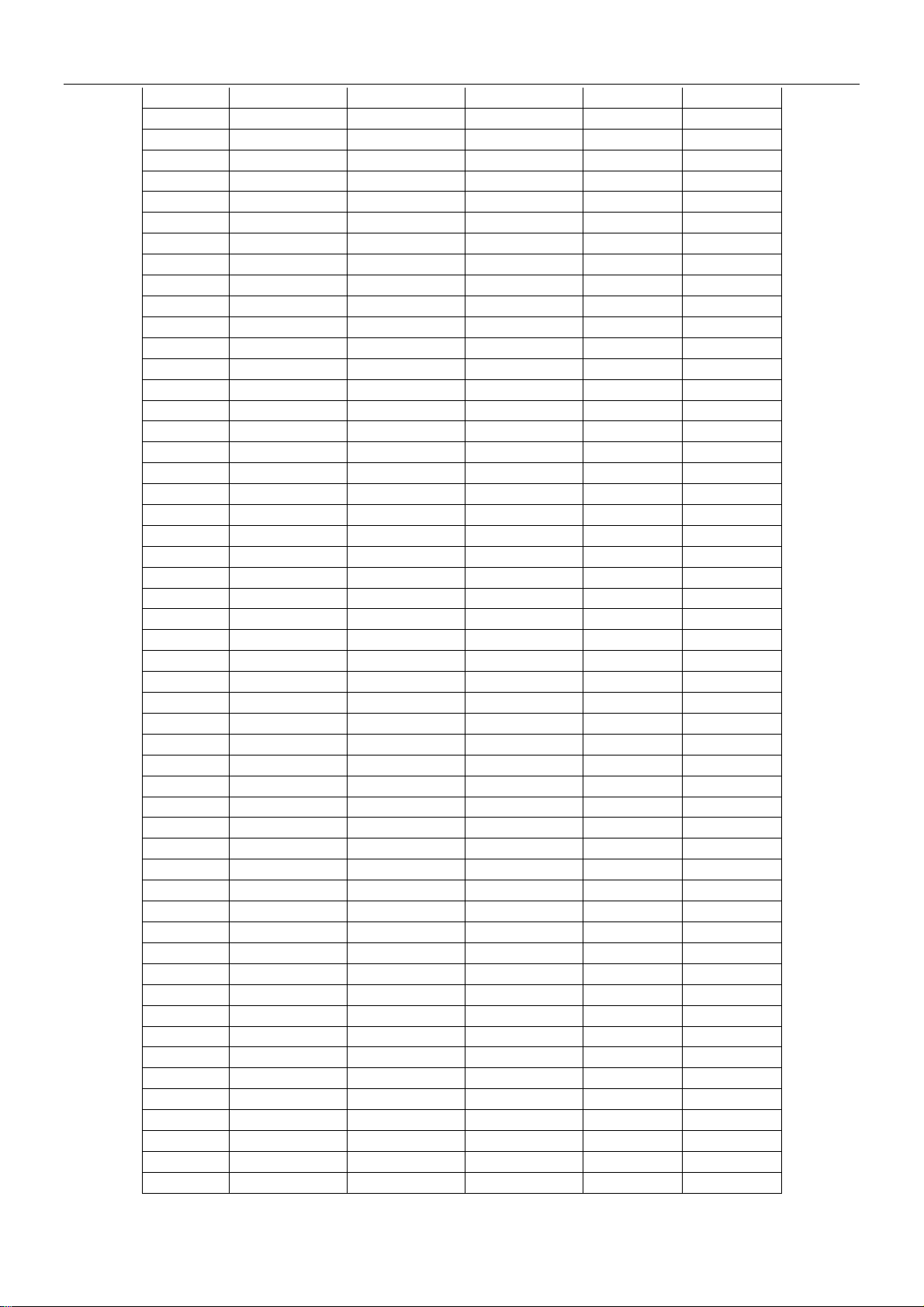
7.2.3 outdoor air sensor and outdoor pipe sensor
R(0)=15K±2% ;B(0/100)=3450K±2% R-T datasheet
Temp.(℃) R(min) (KΩ) R(cent) (KΩ) R(max) (KΩ)
- 25 -
-12.3% 13.8%
-12.4% 13.9%
-12.5% 14.0%
-12.5% 14.2%
-12.6% 14.3%
-12.7% 14.4%
-12.8% 14.5%
-12.9% 14.6%
-13.0% 14.7%
-13.1% 14.9%
-13.2% 15.0%
-13.3% 15.1%
-13.3% 15.2%
-13.4% 15.3%
-13.5% 15.4%
-13.6% 15.5%
-13.7% 15.7%
-13.8% 15.8%
-13.8% 15.9%
-13.9% 16.0%
-14.0% 16.1%
-14.1% 16.2%
-14.2% 16.3%
-14.3% 16.5%
-14.3% 16.6%
-14.4% 16.7%
-14.5% 16.8%
-14.6% 16.9%
-14.7% 17.0%
-14.7% 17.1%
-14.8% 17.2%
-14.9% 17.3%
-15.0% 17.4%
-15.1% 17.5%
-15.1% 17.7%
-15.2% 17.8%
-15.3% 17.9%
-15.4% 18.0%
-15.4% 18.1%
-15.5% 18.2%
-15.6% 18.3%
-15.7% 18.4%
-15.7% 18.5%
-15.8% 18.6%
-15.9% 18.7%
-16.0% 18.8%
-16.0% 18.9%
-16.1% 19.0%
-16.2% 19.1%
ΔR(min) ΔR(max)
Page 26

Shinco Service Manual
-40 106.800 113.500 120.500 -5.90% 6.17%
-39 101.000 107.200 113.700 -5.78% 6.06%
-38 95.600 101.300 107.400 -5.63% 6.02%
-37 90.430 95.760 101.400 -5.57% 5.89%
-36 85.610 90.550 95.740 -5.46% 5.73%
-35 81.070 85.660 90.470 -5.36% 5.62%
-34 76.800 81.060 85.510 -5.26% 5.49%
-33 72.780 76.730 80.860 -5.15% 5.38%
-32 68.990 72.650 76.480 -5.04% 5.27%
-31 65.420 68.820 72.370 -4.94% 5.16%
-30 62.060 65.210 68.500 -4.83% 5.05%
-29 58.890 61.810 64.860 -4.72% 4.93%
-28 55.890 58.610 61.430 -4.64% 4.81%
-27 53.070 55.590 58.210 -4.53% 4.71%
-26 50.410 52.750 55.170 -4.44% 4.59%
-25 47.890 50.060 52.310 -4.33% 4.49%
-24 45.520 47.530 49.610 -4.23% 4.38%
-23 43.270 45.140 47.070 -4.14% 4.28%
-22 41.150 42.890 44.670 -4.06% 4.15%
-21 39.150 40.760 42.410 -3.95% 4.05%
-20 37.260 38.740 40.280 -3.82% 3.98%
-19 35.460 36.840 38.260 -3.75% 3.85%
-18 33.770 35.050 36.360 -3.65% 3.74%
-17 32.160 33.350 34.560 -3.57% 3.63%
-16 30.640 31.740 32.860 -3.47% 3.53%
-15 29.200 30.220 31.260 -3.38% 3.44%
-14 27.840 28.780 29.740 -3.27% 3.34%
-13 26.550 27.420 28.310 -3.17% 3.25%
-12 25.330 26.130 26.950 -3.06% 3.14%
-11 24.170 24.910 25.670 -2.97% 3.05%
-10 23.070 23.75 24.450 -2.86% 2.95%
-9 22.020 22.66 23.300 -2.82% 2.82%
-8 21.030 21.62 22.210 -2.73% 2.73%
-7 20.090 20.63 21.180 -2.62% 2.67%
-6 19.200 19.7 20.200 -2.54% 2.54%
-5 18.350 18.81 19.270 -2.45% 2.45%
-4 17.540 17.97 18.390 -2.39% 2.34%
-3 16.780 17.17 17.560 -2.27% 2.27%
-2 16.050 16.41 16.770 -2.19% 2.19%
-1 15.360 15.69 16.010 -2.10% 2.04%
0 14.700 15 15.300 -2.00% 2.00%
1 14.050 14.35 14.650 -2.09% 2.09%
2 13.430 13.73 14.030 -2.18% 2.18%
3 12.840 13.14 13.440 -2.28% 2.28%
4 12.280 12.58 12.880 -2.38% 2.38%
5 11.750 12.05 12.340 -2.49% 2.41%
6 11.250 11.54 11.830 -2.51% 2.51%
7 10.770 11.05 11.340 -2.53% 2.62%
8 10.310 10.59 10.880 -2.64% 2.74%
9 9.876 10.16 10.440 -2.80% 2.76%
10 9.461 9.738 10.020 -2.84% 2.90%
11 9.067 9.340 9.617 -2.92% 2.97%
12 8.691 8.960 9.234 -3.00% 3.06%
13 8.333 8.598 8.868 -3.08% 3.14%
- 26 -
Page 27

Shinco Service Manual
14 7.9920 8.253 8.519 -3.16% 3.22%
15 7.667 7.924 8.186 -3.24% 3.31%
16 7.357 7.609 7.867 -3.31% 3.39%
17 7.061 7.309 7.563 -3.39% 3.48%
18 6.778 7.023 7.273 -3.49% 3.56%
19 6.509 6.749 6.995 -3.56% 3.64%
20 6.252 6.487 6.729 -3.62% 3.73%
21 6.006 6.238 6.475 -3.72% 3.80%
22 5.772 5.999 6.232 -3.78% 3.88%
23 5.548 5.770 5.999 -3.85% 3.97%
24 5.334 5.552 5.777 -3.93% 4.05%
25 5.130 5.343 5.564 -3.99% 4.14%
26 4.934 5.144 5.360 -4.08% 4.20%
27 4.747 4.952 5.165 -4.14% 4.30%
28 4.568 4.769 4.978 -4.21% 4.38%
29 4.397 4.594 4.798 -4.29% 4.44%
30 4.233 4.426 4.627 -4.36% 4.54%
31 4.077 4.266 4.462 -4.43% 4.59%
32 3.927 4.112 4.304 -4.50% 4.67%
33 3.783 3.964 4.153 -4.57% 4.77%
34 3.645 3.823 4.007 -4.66% 4.81%
35 3.513 3.687 3.868 -4.72% 4.91%
36 3.387 3.557 3.734 -4.78% 4.98%
37 3.266 3.432 3.606 -4.84% 5.07%
38 3.150 3.313 3.483 -4.92% 5.13%
39 3.038 3.198 3.364 -5.00% 5.19%
40 2.932 3.088 3.250 -5.05% 5.25%
41 2.829 2.982 3.141 -5.13% 5.33%
42 2.731 2.880 3.036 -5.17% 5.42%
43 2.636 2.782 2.935 -5.25% 5.50%
44 2.546 2.689 2.838 -5.32% 5.54%
45 2.459 2.599 2.745 -5.39% 5.62%
46 2.375 2.512 2.655 -5.45% 5.69%
47 2.295 2.429 2.569 -5.52% 5.76%
48 2.218 2.349 2.486 -5.58% 5.83%
49 2.1440 2.2720 2.4060 -5.63% 5.90%
50 2.0720 2.1970 2.3290 -5.69% 6.01%
51 2.0040 2.1260 2.2550 -5.74% 6.07%
52 1.9380 2.0580 2.1840 -5.83% 6.12%
53 1.8750 1.9920 2.1150 -5.87% 6.17%
54 1.8140 1.9280 2.0490 -5.91% 6.28%
55 1.7550 1.8670 1.9850 -6.00% 6.32%
56 1.6980 1.8080 1.9240 -6.08% 6.42%
57 1.6440 1.7510 1.8650 -6.11% 6.51%
58 1.5920 1.6960 1.8070 -6.13% 6.54%
59 1.5410 1.6440 1.7520 -6.27% 6.57%
60 1.4930 1.5930 1.6990 -6.28% 6.65%
61 1.4460 1.5440 1.6480 -6.35% 6.74%
62 1.4010 1.4970 1.5990 -6.41% 6.81%
63 1.3570 1.4510 1.5510 -6.48% 6.89%
64 1.3150 1.4070 1.5050 -6.54% 6.97%
65 1.2750 1.3650 1.4600 -6.59% 6.96%
66 1.2360 1.3240 1.4170 -6.65% 7.02%
- 27 -
Page 28

Shinco Service Manual
67 1.1980 1.2840 1.3760 -6.70% 7.17%
68 1.1620 1.2460 1.3360 -6.74% 7.22%
69 1.1270 1.2090 1.2970 -6.78% 7.28%
70 1.0930 1.1740 1.2600 -6.90% 7.33%
71 1.0600 1.1390 1.2240 -6.94% 7.46%
72 1.0290 1.1060 1.1890 -6.96% 7.50%
73 0.9985 1.0740 1.1550 -7.03% 7.54%
74 0.9691 1.0430 1.1220 -7.09% 7.57%
75 0.9407 1.0130 1.0910 -7.14% 7.70%
76 0.9133 0.9841 1.0600 -7.19% 7.71%
77 0.8868 0.9561 1.0300 -7.25% 7.73%
78 0.8612 0.9290 1.0020 -7.30% 7.86%
79 0.8364 0.9028 0.9741 -7.35% 7.90%
80 0.8124 0.8773 0.9473 -7.40% 7.98%
81 0.7893 0.8529 0.9213 -7.46% 8.02%
82 0.7669 0.8292 0.8962 -7.51% 8.08%
83 0.7452 0.8062 0.8718 -7.57% 8.14%
84 0.7242 0.7839 0.8482 -7.62% 8.20%
85 0.7039 0.7624 0.8254 -7.67% 8.26%
86 0.6842 0.7415 0.8032 -7.73% 8.32%
87 0.6652 0.7213 0.7817 -7.78% 8.37%
88 0.6468 0.7017 0.7609 -7.82% 8.44%
89 0.6290 0.6827 0.7407 -7.87% 8.50%
90 0.6117 0.6643 0.7212 -7.92% 8.57%
91 0.5949 0.6465 0.7022 -7.98% 8.62%
92 0.5787 0.6292 0.6838 -8.03% 8.68%
93 0.5630 0.6124 0.6660 -8.07% 8.75%
94 0.5478 0.5962 0.6486 -8.12% 8.79%
95 0.5330 0.5804 0.6318 -8.17% 8.86%
96 0.5187 0.5651 0.6155 -8.21% 8.92%
97 0.5048 0.5503 0.5997 -8.27% 8.98%
98 0.4913 0.5359 0.5843 -8.32% 9.03%
99 0.4783 0.5219 0.5694 -8.35% 9.10%
100 0.4656 0.5084 0.5549 -8.42% 9.15%
101 0.4533 0.4952 0.5408 -8.46% 9.21%
102 0.4414 0.4824 0.5271 -8.50% 9.27%
103 0.4298 0.4700 0.5138 -8.55% 9.32%
104 0.4186 0.4580 0.5009 -8.60% 9.37%
105 0.4077 0.4463 0.4883 -8.65% 9.41%
106 0.3971 0.4349 0.4761 -8.69% 9.47%
107 0.3868 0.4238 0.4643 -8.73% 9.56%
108 0.3768 0.4131 0.4527 -8.79% 9.59%
109 0.3671 0.4027 0.4415 -8.84% 9.63%
110 0.3576 0.3925 0.4306 -8.89% 9.71%
111 0.3485 0.3826 0.4200 -8.91% 9.78%
112 0.3396 0.3731 0.4097 -8.98% 9.81%
113 0.3309 0.3637 0.3997 -9.02% 9.90%
114 0.3225 0.3547 0.3899 -9.08% 9.92%
115 0.3143 0.3458 0.3804 -9.11% 10.01%
116 0.3063 0.3373 0.3711 -9.19% 10.02%
117 0.2986 0.3289 0.3621 -9.21% 10.09%
118 0.2911 0.3208 0.3533 -9.26% 10.13%
- 28 -
Page 29

Shinco Service Manual
119 0.2838 0.3129 0.3448 -9.30% 10.19%
120 0.2767 0.3052 0.3365 -9.34% 10.26%
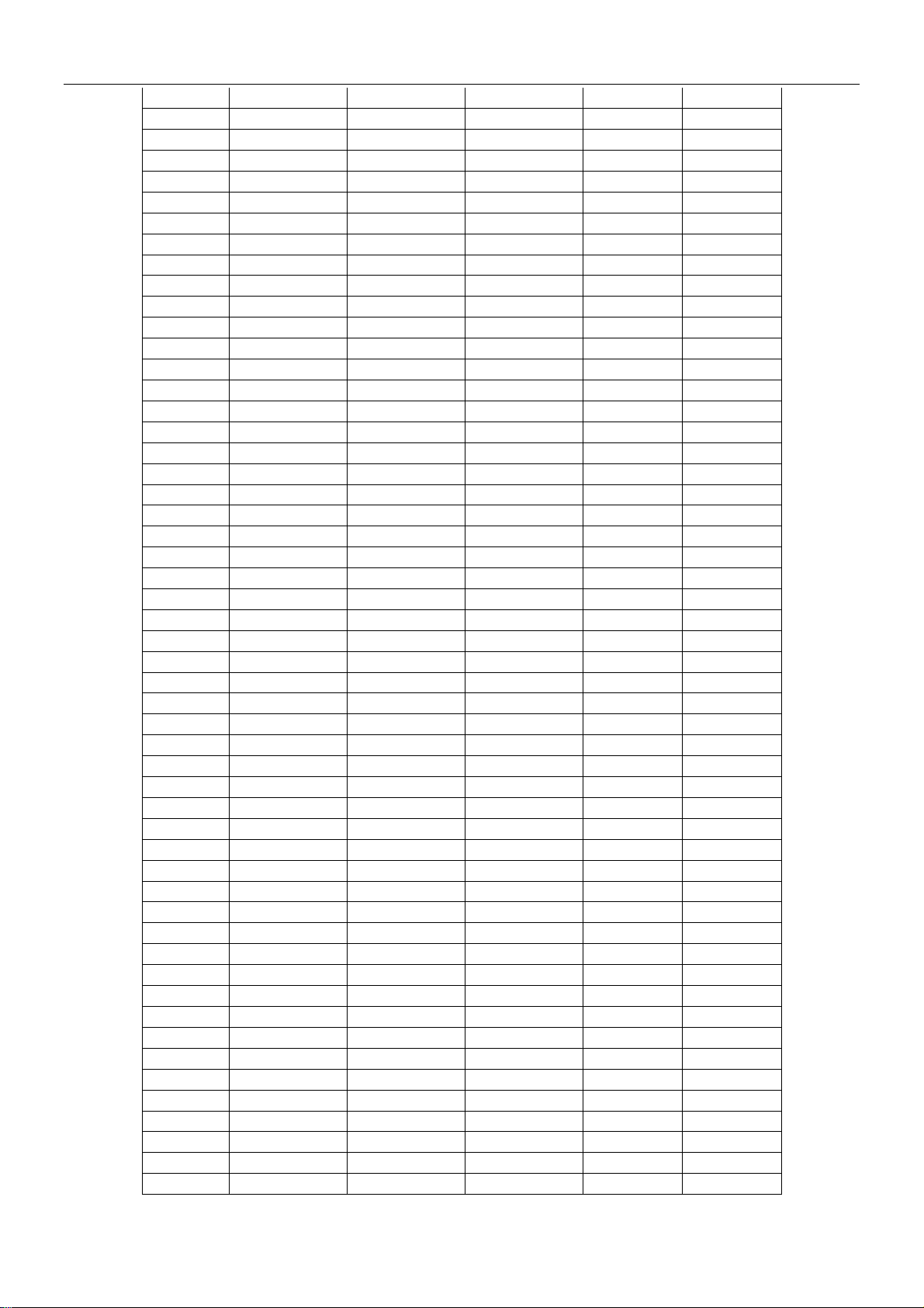
7.2.4 outdoor discharge pipe R(0)=187.25K±6.3% ;B(0/100)=3979K±1% R-T datasheet
Temp.(℃) R(min) (KΩ) R(cent) (KΩ) R(max) (KΩ)
-20 488.35 526.61 565.60 -7.3% 7.4%
-19 461.94 497.84 534.41 -7.2% 7.3%
-18 437.15 470.87 505.17 -7.2% 7.3%
-17 413.89 445.57 477.76 -7.1% 7.2%
-16 392.05 421.83 462.06 -7.1% 9.5%
-15 371.54 399.54 427.94 -7.0% 7.1%
-14 352.27 378.61 405.31 -7.0% 7.1%
-13 334.16 358.96 384.06 -6.9% 7.0%
-12 317.13 340.48 364.10 -6.9% 6.9%
-11 301.11 323.11 345.34 -6.8% 6.9%
-10 286.03 306.77 327.71 -6.8% 6.8%
-9 271.83 291.40 311.13 -6.7% 6.8%
-8 258.46 276.92 295.52 -6.7% 6.7%
-7 245.86 263.29 280.83 -6.6% 6.7%
-6 233.98 250.44 266.99 -6.6% 6.6%
-5 222.78 238.33 253.96 -6.5% 6.6%
-4 212.20 226.91 241.67 -6.5% 6.5%
-3 202.22 216.13 230.07 -6.4% 6.4%
-2 192.79 205.95 219.13 -6.4% 6.4%
-1 183.88 196.34 208.80 -6.3% 6.3%
0 175.45 187.25 199.05 -6.3% 6.3%
1 167.33 178.66 190.00 -6.3% 6.3%
2 159.64 170.53 181.45 -6.4% 6.4%
3 152.37 162.84 173.34 -6.4% 6.4%
4 145.49 155.56 165.67 -6.5% 6.5%
5 138.97 148.66 158.39 -6.5% 6.5%
6 132.80 142.12 151.49 -6.6% 6.6%
7 126.95 135.92 144.94 -6.6% 6.6%
8 121.40 130.03 138.73 -6.6% 6.7%
9 116.13 124.45 132.83 -6.7% 6.7%
10 111.13 119.14 127.22 -6.7% 6.8%
11 106.38 114.10 121.89 -6.8% 6.8%
12 101.87 109.31 116.82 -6.8% 6.9%
13 97.585 104.75 112.00 -6.8% 6.9%
14 93.506 100.42 107.41 -6.9% 7.0%
15 89.625 96.289 103.04 -6.9% 7.0%
16 85.930 92.358 98.873 -7.0% 7.1%
17 82.411 88.612 94.902 -7.0% 7.1%
18 79.058 85.042 91.116 -7.0% 7.1%
19 75.861 81.637 87.503 -7.1% 7.2%
20 72.813 78.388 84.055 -7.1% 7.2%
21 69.904 75.287 80.768 -7.1% 7.3%
22 67.128 72.326 77.618 -7.2% 7.3%
23 64.477 69.498 74.612 -7.2% 7.4%
24 61.945 66.795 71.738 -7.3% 7.4%
25 59.525 64.210 68.990 -7.3% 7.4%
26 57.211 61.739 66.360 -7.3% 7.5%
27 54.998 59.373 63.843 -7.4% 7.5%
ΔR(min) ΔR(max)
- 29 -
Page 30

Shinco Service Manual
28 52.880 57.110 61.433 -7.4% 7.6%
29 50.853 54.942 59.124 -7.4% 7.6%
30 48.913 52.866 56.911 -7.5% 7.7%
31 47.054 50.876 54.791 -7.5% 7.7%
32 45.273 48.939 52.757 -7.5% 7.8%
33 43.565 47.140 50.806 -7.6% 7.8%
34 41.928 45.386 48.934 -7.6% 7.8%
35 40.358 43.703 47.137 -7.7% 7.9%
36 38.852 42.087 45.412 -7.7% 7.9%
37 37.408 40.536 43.755 -7.7% 7.9%
38 36.018 39.047 42.163 -7.8% 8.0%
39 34.685 37.616 40.632 -7.8% 8.0%
40 33.404 36.240 39.162 -7.8% 8.1%
41 32.174 34.919 37.747 -7.9% 8.1%
42 30.991 33.648 36.387 -7.9% 8.1%
43 29.855 32.426 35.078 -7.9% 8.2%
44 28.761 31.250 33.819 -8.0% 8.2%
45 27.710 30.119 32.606 -8.0% 8.3%
46 26.699 29.030 31.439 -8.0% 8.3%
47 25.725 27.982 30.315 -8.1% 8.3%
48 24.788 26.973 29.233 -8.1% 8.4%
49 23.887 26.001 28.190 -8.1% 8.4%
50 23.018 25.065 27.185 -8.2% 8.5%
51 22.182 24.163 26.217 -8.2% 8.5%
52 21.377 23.295 25.284 -8.2% 8.5%
53 20.601 22.457 24.384 -8.3% 8.6%
54 19.854 21.650 23.516 -8.3% 8.6%
55 19.133 20.873 22.680 -8.3% 8.7%
56 18.439 20.123 21.873 -8.4% 8.7%
57 17.770 19.399 21.094 -8.4% 8.7%
58 17.125 18.702 20.343 -8.4% 8.8%
59 16.503 18.029 19.618 -8.5% 8.8%
60 15.903 17.380 18.920 -8.5% 8.9%
61 15.324 16.754 18.245 -8.5% 8.9%
62 14.766 16.150 17.594 -8.6% 8.9%
63 14.228 15.568 16.965 -8.6% 9.0%
64 13.709 15.005 16.358 -8.6% 9.0%
65 13.209 14.463 15.772 -8.7% 9.1%
66 12.726 13.939 15.207 -8.7% 9.1%
67 12.260 13.433 14.681 -8.7% 9.3%
68 11.810 12.946 14.134 -8.8% 9.2%
69 11.376 12.475 13.650 -8.8% 9.4%
70 10.958 12.020 13.133 -8.8% 9.3%
71 10.554 11.581 12.658 -8.9% 9.3%
72 10.164 11.158 12.200 -8.9% 9.3%
73 9.7880 10.749 11.757 -8.9% 9.4%
74 9.4251 10.354 11.330 -9.0% 9.4%
75 9.0749 9.9733 10.917 -9.0% 9.5%
76 8.7370 9.6055 10.518 -9.0% 9.5%
77 8.4109 9.2505 10.134 -9.1% 9.6%
78 8.0962 8.9078 9.7618 -9.1% 9.6%
79 7.7926 8.5770 9.4028 -9.1% 9.6%
80 7.4997 8.2577 9.0562 -9.2% 9.7%
- 30 -
Page 31

Shinco Service Manual
81 7.2170 7.9495 8.7215 -9.2% 9.7%
82 6.9443 7.6520 8.3983 -9.2% 9.8%
83 6.6812 7.3649 8.0883 -9.3% 9.8%
84 6.4273 7.0878 7.7850 -9.3% 9.8%
85 6.1825 6.8204 7.4942 -9.4% 9.9%
86 5.9462 6.5623 7.2135 -9.4% 9.9%
87 5.7184 6.3133 6.9424 -9.4% 10.0%
88 5.4987 6.0731 6.6808 -9.5% 10.0%
89 5.2867 5.8413 6.4284 -9.5% 10.1%
90 5.0827 5.6177 6.1847 -9.5% 10.1%
91 4.8853 5.4018 5.9495 -9.6% 10.1%
92 4.6953 5.1939 5.7226 -9.6% 10.2%
93 4.5121 4.9932 5.5037 -9.6% 10.2%
94 4.3355 4.7997 5.2925 -9.7% 10.3%
95 4.1653 4.6131 5.0840 -9.7% 10.2%
96 4.0012 4.4331 4.8922 -9.7% 10.4%
97 3.8431 4.2596 4.7026 -9.8% 10.4%
98 3.6908 4.0924 4.5198 -9.8% 10.4%
99 3.5440 3.9312 4.3435 -9.8% 10.5%
100 3.4025 3.7759 4.1735 -9.9% 10.5%
101 3.2663 3.6262 4.0097 -9.9% 10.6%
102 3.1351 3.4819 3.8517 -10.0% 10.6%
103 3.0087 3.3429 3.6995 -10.0% 10.7%
104 2.8870 3.2090 3.5528 -10.0% 10.7%
105 2.7699 3.0801 3.4114 -10.1% 10.8%
106 2.6571 2.9559 3.2720 -10.1% 10.7%
107 2.5485 2.8363 3.1440 -10.1% 10.8%
108 2.4441 2.7211 3.0176 -10.2% 10.9%
109 2.3435 2.6103 2.8959 -10.2% 10.9%
110 2.2468 2.5036 2.7787 -10.3% 11.0%
111 2.1537 2.4009 2.6658 -10.3% 11.0%
112 2.0642 2.3021 2.5572 -10.3% 11.1%
113 1.9781 2.2070 2.4526 -10.4% 11.1%
114 1.8954 2.1155 2.3519 -10.4% 11.2%
115 1.8158 2.0276 2.2551 -10.4% 11.2%
116 1.7393 1.9430 2.1619 -10.5% 11.3%
117 1.6657 1.8616 2.0723 -10.5% 11.3%
118 1.5951 1.7834 1.9861 -10.6% 11.4%
119 1.5272 1.7082 1.9032 -10.6% 11.4%
120 1.4619 1.6359 1.8234 -10.6% 11.5%
- 31 -
Page 32

Shinco Service Manual
8. Parts List and exploding view
Exploding view and part list of KFR-25GWZ/BM
Indoor unit
No. Part Name Quantity BOM code
1 Wall Mounted Board 1 e18503
2 Chassis Assembly 1 e535123
3 Cross Fan 1 e19294
4 Left Axial Cover 1 e19257
5 Evaporator Pipe 1 e20747
6 Evaporator 1 eQ00138
7 Frame Assembly 1 e19297
8 Frame 1
9 PVC 1 eb38637
10 Filter 1 7 include 10
11 Display board Assembly 1 e50543
- 32 -
7 include 8
Page 33

12 Indoor 1 eb35153
13 Air Sensor 1 eb11665
14 Pipe sensor 1 eb11666
15 Motor Cover 1 e19258
16 Indoor Motor 1 eb38560
17 Step Motor 1 eb60073
18 Copper Pipe Clip 1 e19256
19 Electric Controlling box Up Cover 1 e19296
20 Indoor Controlling Board 1 e50582
21 Electric Controlling box soleplate 1 e19295
22 Electric Controlling box 1 e18499
23 Remote Controller 1 eb85093
Outdoor unit
Shinco Service Manual
No. Part Name Quantity BOM code
1 Front Frame Assembly 1 e30640/e30641
2 Chassis Assembly 1 e30851/e30852
- 33 -
Page 34

Shinco Service Manual
3 Axial Fan 1 eb38658
4 Motor Bracket 1 e30206
5 Outdoor Air Sensor 1 eb11667
6 Condenser 1 eQ00136
7 Top Cover 1 e14335/e14336
8 4-way valve winding 1 eb40103
9 4-way valve 1 eb40090
10 discharge sensor 1 eb11664
11 pipe sensor 1 eb11667
12 Capillary assembly 1 e20603
13 middle clipboard 1 e15607
14 outdoor motor 1 eb61530
15 compressor 1 eb15582
16 valve board 1 e14339/e14340
17 high pressure valve 1 eb40092
18 low pressure valve 1 eb40093
19 electric controlling box cover 1 e30745
20 electric controlling box 1 e30639
21 Fin 1 e30702
22 outdoor driver board 1 e52138
23 Outdoor terminal block 1 eb35154/eb35153
24 outdoor PFC board 1 e52137
25 Right Side Panel 1 e30644/e30645
26 big handle 1 e14219
- 34 -
Page 35

Shinco Service Manual
Exploding view and part list of KFR-35GWZ/BM
Indoor unit
No. Part Name Quantity BOM code
1 Wall Mounted Board 1 e18503
2 Chassis Assembly 1 e535123
3 Cross Fan 1 e19294
4 Left Axial Cover 1 e19257
5 Evaporator Pipe 1 e20748
6 Evaporator 1 eQ00138
7 Frame Assembly 1 e19297
8 Frame 1
7 include 8
9 PVC 1 eb38637
10 Filter 1 7 include 10
11 Display board Assembly 1 e50543
- 35 -
Page 36

Shinco Service Manual
12 Indoor terminal block 1 eb35153
13 Air Sensor 1 eb11665
14 Pipe sensor 1 eb11666
15 Motor Cover 1 e19258
16 Indoor Motor 1 eb38560
17 Step Motor 1 eb60073
18 Copper Pipe Clip 1 e19256
Electric Controlling box Up
19
Cover 1 e19296
20 Indoor Controlling Board 1 e52125
Electric Controlling box
21
soleplate 1 e19295
22 Electric Controlling box 1 e18499
23 Remote Controller 1 eb85093
Outdoor unit
- 36 -
Page 37

Shinco Service Manual
No. Part Name Quantity BOM code
1 Chassis Assembly 1 e30640/e30641
2 Front Frame Assembly 1 e14598/e14599
3 Axial Fan 1 eb38658
4 Motor Bracket 1 e30308
5 Outdoor Air Sensor 1 eb11667
6 Condenser 1 eQ00137
7 Top Cover 1 e14335/e14336
8 4-way valve winding 1 eb40103
9 4-way valve 1 eb40094
10 discharge sensor 1 eb11664
11 pipe sensor 1 eb11667
12 Capillary assembly 1 e20617
13 middle clipboard 1 e15607
14 outdoor motor 1 eb61530
15 compressor 1 eb15599
16 valve board 1 e14339/e14340
17 high pressure valve 1 eb40092
18 low pressure valve 1 eb40096
19 electric controlling box cover 1 e30745
20 electric controlling box 1 e30639
21 Fin 1 e30702
22 outdoor driver board 1 e52138
23 Outdoor terminal block 1 eb35154/eb35153
24 outdoor PFC board 1 e52137
25 Right Side Panel 1 e30644/e30645
26 big handle 1 e19306
- 37 -
Page 38

Shinco Service Manual
8.3 Exploding view and part list of KFR-50GWZ/BM
Indoor unit
No. Part Name Quantity BOM code
1 Wall Mounted Board 1 e17978
2 Chassis Assembly 1 e19341
3 Cross Fan 1 eb38669
4 Left Axial Cover 1 e17980
5 Evaporator Pipe 1 e20509
6 Evaporator 1 eQ00139
7 Frame Assembly 1 e19340
8 Frame 1
7 include 8
9 PVC 1 e19383
- 38 -
Page 39

Shinco Service Manual
10 Filter 1 e17989
11 Display board Assembly 1 e50543
12 Indoor terminal block 1 eb35153
13 Air Sensor 1 eb10007
14 Motor Cover 1 e17982
15 Indoor Motor 1 eb38668
16 Step Motor 1 eb38162
17
18 Copper Pipe Clip 1 e17987
19 Electric Controlling box 1 e30706
20 Electric Controlling box soleplate 1 e19343
21 Indoor Controlling Board 1 e50613
22 Electric Controlling box top Cover 1 e30707
23 Remote Controller 1 eb85093
Outdoor unit
Flume 1 e19342
- 39 -
Page 40

Shinco Service Manual
No. Part Name Quantity BOM code
1 Chassis Assembly 1 e30708/e30709
2 Front Frame Assembly 1 e30741/e30742
3 Axial Fan 1 eb38670
5 Motor Bracket 1 e30684
6 Outdoor Air Sensor 1 eb10011
7 Condenser 1 eQ00140
8 Top Cover 1 e30680/e30681
9 4-way valve winding 1 eb40103
10 4-way valve 1 eb40094
11 discharge sensor 1 eb11664
12 pipe sensor 1 eb11660
13 Capillary assembly 1 e22179
14 middle clipboard 1 e30679
4 outdoor motor 1 eb61531
23 compressor 1 eb15656
24 valve board 1 e30749/e30750
26 high pressure valve 1 eb40092
25 low pressure valve 1 eb40137
15 electric controlling box cover 1 e30683
16 electric controlling box 1 e30682
17 High-frequency inductance 1 eb38674
18 outdoor driver board 1 e50615
19 Outdoor terminal block 1 eb35154
20 outdoor power board 1 e50614
22 Right Side Panel 1 e30710/e30711
21 big handle 1 e19306
- 40 -
Page 41

Shinco Service Manual
Exploding view and part list of KFR-70GWZ/BM
Indoor unit
No. Part Name Quantity BOM code
1 Wall Mounted Board 1 e18416
2 Air outlet vent assembly 1 e535126
3 Chassis Assembly 1 e19326
4 Cross Fan 1 eb38667
5 indoor connect pipe 1/2 1 e20442/e18771
6 Evaporator 1 eQ00141
7 Part Name 1 e19328
8 PVC 1 e19384
- 41 -
Page 42

Shinco Service Manual
9 Remote Controller 1 eb85093
10 Display board Assembly 1 e50543
11 Air Sensor 1 eb10007
12 Indoor Controlling Board 1 e50610
13 Indoor power Board 1 e50609
14 Electric Controlling box top Cover 1 e19325
15 Electric Controlling box 1 e19324
16 Indoor terminal block 1 e35153
17 Indoor Motor 1 eb61535
18 Indoor Motor cover 1 e19339
19 Step Motor 1 eb38229
Outdoor unit
- 42 -
Page 43

Shinco Service Manual
No. Part Name Quantity BOM code
1 Chassis Assembly 1 e30478/e30479
2 Front Frame Assembly 1 e30693/e30694
3 Axial Fan 1 eb38666
4 Outdoor motor 1 eb61532
5 Motor Bracket 1 e30512
6 middle clipboard 1 e19166
7 outdoor air sensor 1 eb10011
8 Condenser 1 eQ00142
9 Top Cover 1 e15838/e15839
10 outdoor pipe sensor 1 eb11660
11 High-frequency inductance 1 eb38676
12 outdoor power board 1 e50611
13 outdoor driver board 1 e50612
14 electric controlling box cover 1 e30252
15 electric controlling box 1 e30697
16 Outdoor terminal block 1 eb35156
17 Capillary assembly 1 e22092
18 4-way valve 1 eb40741
19 4-way valve winding 1 eb40742
20 big handle 1 e14219
21 valve board 1 e15831/e15832
22 low pressure valve 1 e40719
23 high pressure valve 1 e40718
24 compressor 1 eb15630
25 indoor to outdoor connect pipe 2 e21093/e21094
26 Right Side Panel 1 e30695/e30696
27 Right Frame Panel 1 e15835/e30494
- 43 -
Page 44

Part II
1. Service warning
Part I General Warnings
1、The service person should wear safety belt if working more than 2.5m above the ground.
2、If working above ground level, measures should be adopted to prevent the outdoor unit or tools
from falling and causing injuries or damage.
3、Check the customers power supply before testing the unit.
4、The power supply should be switched OFF when disassembling the casing and electrical
components.
5、Take care to prevent a frost bite injury when charging with refrigerant.
6、Do not over pressurize the Freon cylinder. The over exposure, high temperature or dropping the
Shinco Service Manual
cylinder should be avoided, otherwise, it could cause an explosion.
7、If there is need to pressure test the system, Dry Nitrogen should be used.
Part II Warnings of repair operation
1、 The high capacity electrolytic capacitor is used in the electric control cabinet of the outdoor unit.
Even if the power plug is unplugged; this capacitor will retain a residual charge for a certain time. In
order to avoid electric shock, please do not touch the control board as soon as the power is switched
OFF. If it is necessary to change the control board of the outdoor unit, please switch OFF the power
supply first. After the light emitting diode of outdoor control board extinguishes or the power is
switched OFF for >30 sec’s, let the high capacity capacitor discharges fully. The replacement can
only be conducted after checking the high capacity capacitor has discharged fully with an electrical
meter.
2、 After making use of self-diagnosis of faults on the site, switch the snap switch to “demonstrate”,
re-electrify the air-conditioner so that the system can erase the stored fault information of former
self-diagnosis. Switch the snap switch to “ON” again, prepare for re-starting the air-conditioner.
Because the LS-LT1508V model air-conditioner has not been fitted with an E
device of fault information), the fault information will be automatically erased after switching OFF
the power.
2
PROM (storage
3、 For diagnosis of the system fault, first it is suggested to check whether the electrical wiring is
reliable and correct. After eliminating this cause, continue to seek other causes.
- 44 -
Page 45

2. Frequency table
F0 F1 F2 F3 F4 F5 F6 F7 F8 F9 F10
Shinco Service Manual
KFR-25GWZ/BM
COOLING
KFR-25GWZ/BM
HEATING
KFR-35GWZ/BM
COOLING
KFR-35GWZ/BM
HEATING
KFR-50GWZ/BM
COOLING
KFR-50GWZ/BM
HEATING
KFR-70GWZ/BM
COOLING
KFR-70GWZ/BM
HEATING
0 30 35 40 45 52 55 58 66 69 73
0 30 35 40 45 52 55 59 66 69 73
0 30 36 42 48 54 61 66 72 78 84
0 30 36 42 48 54 61 66 72 78 84
0 30 36 43 49 56 64 72 77 82 87
0 30 36 43 49 58 67 77 81 84 87
0 30 34 39 44 48 52 57 62 67 72
0 30 35 40 46 51 56 62 67 73 78
3. Method of Testing the System at a Fixed Frequency
Cooling
Capacity(MIDDLE
FREQUENCY)
1. Start the air conditioner
2.Operate remote controller as following
Mode : Cool mode
Set temp. : 18℃
indoor fan : high
Press ‘powerful’ button 5 times with 10 seconds.
Cooling rated capacity Heating Capacity(MIDDLE
FREQUENCY)
Mode : Cool mode
Set temp. : 16℃
indoor fan : high
Mode : heat mode
Set temp. : 28℃
indoor fan : high
Heat rated capacity
Mode : heat mode
Set temp. : 30℃
indoor fan : high
- 45 -
Page 46

Shinco Service Manual
4. Running mode
4.1. Defrosting
1. Entry condition:
Defrosting starts when meeting one of the following conditions
a. The temperature of outdoor heat exchanger remains consecutively lower than 3°c for more than
temperature remains consecutively
b. The temperature of outdoor heat exchanger remains consecutively lower than 3°c for more than
temperature remains consecutively
c. The temperature of outdoor heat exchanger remains consecutively lower than 3°c for more than
temperature remains consecutively
2. .Ending condition of defrosting
If one of following conditions is satisfied, end the defrosting and turn into heating mode:
a. The defrost time has reached to 10 minutes.
b. When the temperature of outdoor heat exchanger rises up to
3.Defrosting Actions:
Max. 10 minutes
20s 20 s
ON 10s 10S
Compressor. OFF
ON ON
4 way valve OFF
ON ON
Outdoor fan OFF
ON
-6°c for more than 3 minutes
-4°c for more than 3 minutes
-3°c for more than 3 minutes
15°C.
4.2. Fan-only mode
The outdoor unit doesn’t operation, only the indoor fan runs. The fan speed can be set on HIGH MID LOW, and the
louver can be regulated by remote controller.
4.3. Cooling mode
40 minutes, and the
80 minutes, and the
120 minutes, and the
4.3.1 Compressor frequency controlling
a. Frequency control when starting
Temperature difference= Room temperature (RT)-Set temperature (ST)
RT-ST
b. Frequency control during operation
The frequency will change according to the RT-ST, and details see following fig.
- 46 -
Page 47

Shinco Service Manual
A-—E: rise the present frequency one class (for example, from F3 to F4)
F: Frequency keep unchanged
G:lower the present frequency on class( for example, from F4 to F3), and the
maximum frequency is F3 in G area.
H:The compressor stops.
c. Frequency will change due to outdoor temperature, details see following fig.
4.3.2 Indoor heat exchanger anti-frozen
When indoor air sensor temperature is less than 3℃, the frequency will lower down to protect
indoor heat exchanger. When indoor air sensor temperature is higher than 6℃ for more than 10 minutes,
the air conditioner will return to former mode.
When indoor air sensor temperature is less than -1℃,the compressor will stop to protect indoor
heat exchanger. When indoor air sensor temperature is higher than 6℃ for more than 10 minutes, the
air conditioner will return to former mode.
4.3.3 Outdoor heat exchanger anti-overheated
When condenser temperature is higher than 54℃, the compressor frequency will be
lowered down to protect the heat exchanger , and the outdoor fan runs in high speed. When condenser
temperature lower down to 52℃, the compressor frequency rise up, and when the condenser temperature
lower to 50℃ and keep for 5 minutes, and compressor frequency will rise to former value.
- 47 -
Page 48

Shinco Service Manual
When condenser temperature is higher than 60℃, the compressor will stop, and hen the condenser
temperature lower to 50℃ and keep for 5 minutes, and compressor frequency will rise to former value
4.4. Dehumidifying mode
4.4.1 Temperature set and motor control in dehumidifying mode
The compressor and outdoor fan run in dehumidifying mode similar as cooling mode,
and the temperature can be set.
The indoor motor speed need to be set in low speed.
4.4.2 Compressor frequency on dehumidifying mode
The maximum frequency in dehumidifying mode is F3,and the frequency changes as following
fig.
4.4.3 The louver control in dehumidifying mode
The Louver control in dehumidifying mode is same as cooling mode.
4.4.4 Protection
The Indoor heat exchanger anti-frozen and Outdoor heat exchanger anti-overheat is same as
cooling mode.
4.5. Heating mode
4.5.1 Compressor frequency controlling
a. Frequency control when starting
Temperature difference= Room temperature (RT)-Set temperature (ST)
RT-ST
- 48 -
Page 49

Shinco Service Manual
b. Frequency control during operation
The frequency will change according to the RT-ST, and details see following fig.
A-—E: rise the present frequency one class (for example, from F3 to F4)
F: Frequency keep unchanged
G:Lower the present frequency on class (for example, from F4 to F3), and the
maximum frequency is F3 in G area.
H:The compressor stops.
c. Frequency will change due to outdoor temperature, details see following fig.
- 49 -
Page 50

Shinco Service Manual
4.5.2 Indoor heat exchanger anti-overheated
When indoor exchanger temperature is higher than 50℃, the compressor frequency
will be lowered down to protect the heat exchanger. When indoor exchanger temperature lower down
to 46℃, the compressor frequency rise up, and when the
℃ and keep for 5 minutes, and compressor frequency will rise to former value.
indoor exchanger temperature lower to 44
When condenser temperature is higher than 54℃, the compressor will stop, and hen the condenser
temperature lower to 44℃ and keep for 5 minutes, and compressor frequency will rise to former value
4.6 Emergency Operation
The set temperature is 24 , and the fan speed is AUTO during emergency operation.℃
Press emergency switch within 5 s during stand-by mode, and the air conditioner starts emergency mode if
there is DU sound from indoor unit.
Press emergency switch during operation mode, and the air conditioner can be turned off.
Note: During emergency mode, the air conditioner will turn to the mode set by remote controller after
receiving signal from remote controller.
4.7 Sleeping operation
Cooling mode: Press sleep button, the fan speed lower down one class automatically ( HI-ME-LO-VL). The
set temperature rise one degree, and rise one degree again one hour later, then keep it.
Heating mode: Press sleep button, the fan speed lower down one class automatically (HI-ME-LO-VL). The set
temperature lower one degree, and lower one degree again one hour later, then keep it.
Note: During sleep mode, if change the set temperature, the a ctual set temperature is new set temperature
plus lowered or rised temperature.
4.8 Auto restart:
The air conditioner will restart with set mode automatically after power on again, and this can be canceled by
user, and to cancel this mode follow the following instructions:
1. Press ON/OFF button 6 times within 7 s, and the AUTO restart mode can be cancelled.
2. Press ON/OFF button 6 times within 7s, and the AUTO restart mode can be set again.
- 50 -
Page 51

Shinco Service Manual
4.9 Refrigerant charge mode
Entry condition:
Press the emergency switch over 5 seconds, there will be three “DU” sound in the indoor unit, and start
the unit with the remote controller.
Actions
1. On cooling mode, the indoor fan speed is low
2. Cancel the mode
Turn off the air conditioner with remote controller
:
the frequency is fixed on F6,
:
5. Protection
5.1 Compressor protection
5.1.1 High pipe discharge temperature protection
When discharge pipe temperature is higher than T3, the compressor frequency will
be lowered, when discharge pipe temperature lower to T1, the frequency will rise, and the
frequency will be limited one class than former one. When the discharge pipe temperature
lower to T2 and keep for 10 minutes, the frequency will return to former one.
When discharge pipe temperature is higher than T4, the compressor stop and the
outdoor motor stop 15s later. When discharge pipe temperature lower to T1 and the unit
restart after 3 minutes.
T1 T2 T3 T4
KFR-25GWZ/BM
KFR-35GWZ/BM
KFR-50GWZ/BM
KFR-70GWZ/BM
90 95 105 110
5.1.2 Sensor protection
There is thermal sensor on compressor, and the compressor will stop when the temperature is too
high, and the outdoor motor will stop 15s later. When the temperature return normal value, the
compressor will restart 3 minutes later.
5.1.3 Compressor relay start protection
The compressor will restart 3 minutes after stop.
5.2 Current protection
When outdoor current is higher than I1, the compressor frequency will be limited and prohibited to rise. When the
current is higher than I2, and the compressor frequency will lower until the current is lower than I1.
When outdoor current is lower than I3, the compressor will stop.
The detailed current value see below table:
- 51 -
Page 52

Shinco Service Manual
KFR-25GWZ/BM
MODE I1 I2 I3
COOLING AND DEHUMIDIFYING 7.1 8.3 10.3
HEATING 6.3 7.5 9.5
KFR-35GWZ/BM
MODE I1 I2 I3
COOLIGN AND DEHUMIDIFYING 8.1 9.6 11.6
HEATING 10.5 12 14
KFR-50GWZ/BM
MODE I1 I2 I3
COOLING AND DEHUMIDIFYING 8.5 10.5 12.5
HEATING 8.5 10.5 12.5
KFR-70GWZ/BM
MODE I1 I2 I3
COOLIGN AND DEHUMIDIFYING 12 16 18
HEATING 14 19 21
5.3 Low voltage protection
The compressor frequency changes as following fig. during low voltage:
When voltage value lower than 190V and keep for 10s, the low voltage protection start,
and when voltage value rise to 195V and keep for 10s, the low voltage proteccion finish.
When voltage value lower than 158V, the unit turn off, when voltage rise to 162V, keep
for 10s, the unit restart.
- 52 -
Page 53

Shinco Service Manual
6、Display lamp
6.1 Indoor display
5 6 7
1 2 3 4
1 Dual-Digital lamp; 2 Timer Lamp; 3 Operation lamp; 4 Protection Lamp; 5 cooling mode; 6 dehumidify mode;
7 heating mode 。
6.2 Fault code display
KFR-25GWZ/BM、KFR-35GWZ/BM
Item FAULT CODE CHECK POINT COUNT MEASURE
CHECK IF THE INDOOR UNIT MATCH OUTDOOR UINT CHANGE WRONG UNIT。
1、 CHECKTHE VALUE OF SENSOR
2、 OUTDOOR POWER BOARD IS FAULT(CHECK
CAPICATOR)
CHANGE SENSOR
CHANGE POWER BOARD
1
2
INDOOR UNIT DON’T MATCH
OUTDOOR UNIT
OUTDOOR DISCHARGE PIPE
SENSOR FAULT
EP
E0
- 53 -
Page 54

Shinco Service Manual
1.CHECK IF THE CONNECTING WIRING IS CONNECT
WELL
2.TEST THE VOLTAGE VALUE BETWEEN L4 AND S,
IF IT ‘S CHANGE REGULARLY,THE SINGAL
TRANSFERING BETWEEN INDOOR AND OUTDOOR UNIT
1.FIX THE WIRING AGAIN。
2.CHANGE RELATE PCB BOARD
IS GOOD,
WHEN IT‘S NO CHANGE
3
COMMUNICATION FAULT
BETWEEN INDOOR UNIT AND
OUTDOOR UNIT
E4
IF VALUE IS BELOW 14V, THE INDOOR PCB BOARD
IS FAULT,CHANGE IT.
IF VALUE IS OVER 14V,THE OUTDOOR PCB IS FAULTY
3)CHECK IF THERE IS LED FLASHING ON THE
OUTDOOR PCB
IF THERE IS NO FLASHING,CHECK VOLTAGE VALUE
FROM POWER BOARD TO PFC BOARD, BETWEEN ACL AND
CAN ON PFC BOARD
IF IT’S NOT 220V, CHANGE POWER BOARD
IF IT’S 220V,CHANGE PFC BOARD
4
5
6
7
8
COMPRESSOR DRIVER BOARD
IS
OURDOOR AIR SENSOR IS
FAULTY
OUTDOOR PIPE SENSOR IS
FAULT
INDOOR AIR SENSOR IS
FAULTY
INDOOR PIPE SENSOR IS
FAULTY
EA
E6
E1
E2
CHECK OUTDOOR DRIVER BOARD CHANGE DRIVER BOARD
1、 CHECK THE SENDOR VALUE
2、 POWER BOARD IS FAULT
3、 CHECK THE SENSOR VALUE
4、 INDOOR BOARD IS FAULT
CHANGE SENSOR
CHANGE POWER BAORD。
CHANGE SENDOR
CHANGE INDOOR BOARD
9 POWER BOARD IS FAULT E8 OUTDOOR POWER BOARD IS FAULT CHANGE THE POWER BOARD
10 POWER BOARD IS FAULT E9 OUTDOOR POWER BOARD IS FAULT CHANGE THE POWER BOARD
DRIVER BOARD IS FAULT DRIVER BOARD IS FAULT
11 DRIVER BOARD IS FAULT E5
12
OUDOOR COMMUNICATION
FAULTY
EC
- 54 -
CHECK IF WIRINGS BETWEEN POWER BOARD AND
DRIVER BOARD ARE CONNECTED WELL
FIX THE WIRING BETWEEN POWER BOARD AND
DRIVER BOARD
Page 55

Shinco Service Manual
13 INDOOR MOTOR IS FAULT E3
1、INDOOR MOTOR OR INDOOR MOTOR CAPACITOR IS
FAULT
2、INNER WIRING DON’T CONNECT WELL
3、INDOOR PCB IS FAULT
4、INDOOR MOTOR IS BLOCKED
1、CHANGE MOTOR OR CAPACITOR
2、FIX THE WIRINGS
3、CHANGE INDOOR PCB
4、REMOVE THE BLOCKING
14 INDOOR PCB BAORD IS FAULTY EE INDOOR PCB BAORD IS FAULTY INDOOR PCB BAORD IS FAULTY
1
OUTDOOR DISCHARGE TEMP IS
TOO HIGH
P1
2 DRIVER BOARD PROTECTION P7
1、 CHECK IF THE OUTLET IS BLOCKED OR THE
CONDENSOR IS DIRTY
2、 CHECK THE OUTDOOR MOTOR WORK NORMALLY
3、CHECK IF THE REFRIGERANT IS CHARGED TOO MUCH
1、 CHECK IF THE REFRIGERANT IS CHARGED TOO
MUCH
2、 CHECK IF THE COMPRESSOR IS BLOCKED
1、REMOVE OBSTACLE AROUND OUTDOOR UNIT OR
WASH THE CONDENSER
2、CHANGE OUTDOOR MOTOR OR MOTOR CAPACITOR
3、REGULATE THE QUANTITY OF REFRIGERANT
1、REGULATE THE QUANTITY OF REFRIGERANT
2、CHANGE COMPRESSOR
3、CHANGE IPM MOLD
3、 IPM MOLD IS FAULT
3 THE VOLTAGE IS NOT STABLE P3 CHECK THE POWER SUPPLY RESTART THE AIR CONDITIONER
4
ELECTRIC CURRENT IS TOO
HIGH
P2
1、CHECK IF THE REFRIGERANT IS CHARGED TOO MUCH
2、CHECK IF THE VOLTAGE IS TOO LOW, POWER
WRINGIS TOO THIN OR TOO LONG OR CONTACT
BADLY
3、 CHECK IF THE OUTLET IS BLOCKED OR THE
CONDENSOR IS DIRTY
1、REGULATE THE QUANTITY OF REFRIGERANT
2、UPDATING POWER SUPPLY, CHANG POWER WIRING
3、 REMOVE OBSTACLE AROUND OUTDOOR UNIT OR
WASH THE CONDENSER
4、CHANGE OUTDOOR MOTOR OR MOTOR CAPACITOR
4、 CHECK THE OUTDOOR MOTOR WORK NORMALLY
5 OCR TRIPED P4
1.COMPRESSOR OCR IS OPEN CURCUIT
2. CHECK IF THE OCR TEMPERATURE IS TOO HIGH
AND OCR TRIPED
1、 CHANGE OCR OR COMPRESSOR
2、TURN OFF THE AIR CONDITIONER, AND RESTART
IT 2 HOUR LATER
3、IF AIR CONDITIONER IS ON AND OFF
REGULARLY, CHECK OUTDOOR MOTOR OR MOTOR
CAPACITOR, THE OUTLET IS BLOCKED OR THE
CONDENSOR IS DIRTY
6
INDOOR PIPE TEMP. IS TOO
HIGH WHEN HEATING
P5
1、CHECK INDOOR MOTOR WORK NORMALLY
2、CHECK FILTER NET OR EVAPERATOR IS DIETY
1、CHANGE OUTDOOR MOTOR OR MOTOR CAPACITOR。
2、 WASH THE FILETE NET OR EVAPERATOR
7 OUTDOOR PIPE TEMP. ID TOO P6 1、CHECK IF THE REFRIGERANT IS CHARGED TOO MUCH 1、REGULATE THE QUANTITY OF REFRIGERANT
- 55 -
Page 56

Shinco Service Manual
HIGH 2、CHECK IF THE VOLTAGE IS TOO LOW, POWER
WRINGIS TOO THIN OR TOO LONG OR CONTACT
BADLY
3、CHECK IF THE OUTLET IS BLOCKED OR THE
2、UPDATING POWER SUPPLY, CHANG POWER WIRING
3、REMOVE OBSTACLE AROUND OUTDOOR UNIT OR
WASH THE CONDENSER
CONDENSOR IS DIRTY
8 DRIVER BOARD IS FAULT P0 DRIVER BOARD IS FAULT CHANGE DRIVER BAORD
- 56 -
Page 57

Shinco Service Manual
KFR-50GWZ/BM、KFR-70GWZ/BM
Item FAULT CODE CHECK POINT COUNT MEASURE
1
E1
INDOOR AIR SENSOR IS FAULTY
2
3
4
INDOOR PIPE SENSOR IS FAULTY
INDOOR IN-PHASE MOTOR IS FAULT
COMMUNICATION FAULT BETWEEN
E2
E3
E4
INDOOR UNIT AND OUTDOOR UNIT
5
6 OUTDOOR SENSOR IS FAULT E6
7 INDOOR MOTOR FAULTY E7
8 COMMUNICATION SIGNAL IS
DRIVER BOARD IS FAULT )
NOT GOOD
E5
E8
1、CHECK THE SENSOR VALUE
2、INDOOR BOARD IS FAULT
-----------------------
1、CHECK IF THE CONNECTING WIRING IS CONNECT WELL
2、TEST THE VOLTAGE VALUE BETWEEN L4 AND S, IF IT ‘S
CHANGE REGULARLY,THE SINGAL TRANSFERING BETWEEN
INDOOR AND OUTDOOR UNIT IS GOOD,
WHEN IT’S NO CHANGE
IF VALUE IS BELOW 14V, THE INDOOR PCB BOARD IS FAULT,
CHANGE IT.
IF VALUE IS OVER 14V,THE OUTDOOR PCB IS FAULTY
3、CHECK IF THERE IS LED FLASHING ON THE OUTDOOR PCB
IF THERE IS NO FLASHING,CHECK VOLTAGE VALUE FROM
POWER BOARD TO PFC BOARD, BETWEEN ACL AND CAN ON PFC
BOARD
IF IT’S NOT 220V, CHANGE POWER BOARD
IF IT’S 220V,CHANGE PFC BOARD
DRIVER BOARD IS FAULT DRIVER BOARD IS FAULT
1、CHECK THE SENDOR VALUE
2、POWER BOARD IS FAULT
----------------------
CHECK IF THE COMMUNICATION WIRING IS CONNECTED WELL.
CHECK IF POWER BOARD OR DRIVER BOARD IS FAULT
CHANGE SENDOR
CHANGE INDOOR BOARD
-----------------------
1、FIX THE WIRING AGAIN。
2、CHANGE RELATE PCB BOARD
CHANGE SENSOR
CHANGE POWER BAORD。
-----------------------
FIX THE COMMUNICATION WELL
CHANGE THE PCB BOARD
- 57 -
Page 58

Shinco Service Manual
9
10
11
12 IPDU IS FAULT P3 ----------------------- -----------------------
13
DRIVER BOARD IS FAULT
OCR TRIPED
POWER BOARD IS FAULT
INDOOR UNIT DON’T MATCH
P0
P1
P2
P4
DRIVER BOARD IS FAULT DRIVER BOARD IS FAULT
1、COMPRESSOR OCR IS OPEN CURCUIT
2、 CHECK IF THE OCR TEMPERATURE IS TOO HIGH AND OCR
TRIPED
OUTDOOR POWER BOARD IS FAULT CHANGE THE POWER BOARD
CHECK IF THE INDOOR UNIT MATCH OUTDOOR UINT CHANGE WRONG UNIT。
1、CHANGE OCR OR COMPRESSOR
2、TURN OFF THE AIR CONDITIONER, AND RESTART
IT 2 HOUR LATER
3、IF AIR CONDITIONER IS ON AND OFF
REGULARLY, CHECK OUTDOOR MOTOR OR MOTOR
CAPACITOR, THE OUTLET IS BLOCKED OR THE
CONDENSOR IS DIRTY
OUTDOOR UNIT
14
15
16 PFC FAULTY P7 OUTDOOR PFC BOARD IS FAULT CHANGE PFC BOARD
17 INDOOR MOTOR FEEDBACK
ELECTRIC CURRENT IS TOO HIGH
THE VOLTAGE IS NOT STABLE
FAULTY
P5
P6
P8 ----------------------- -----------------------
1、CHECK IF THE REFRIGERANT IS CHARGED TOO MUCH
2、CHECK IF THE VOLTAGE IS TOO LOW, POWER WRINGIS TOO
THIN OR TOO LONG OR CONTACT BADLY
3、 CHECK IF THE OUTLET IS BLOCKED OR THE CONDENSOR
IS DIRTY
4、CHECK THE OUTDOOR MOTOR WORK NORMALLY
CHECK THE POWER SUPPLY
1、REGULATE THE QUANTITY OF REFRIGERANT
2、UPDATING POWER SUPPLY, CHANG POWER WIRING
3、REMOVE OBSTACLE AROUND OUTDOOR UNIT OR
WASH THE CONDENDSOR
4、CHANGE OUTDOOR MOTOR OR MOTOR CAPACITOR
RESTART THE AIR CONDITIONER
Note: The fault code doesn’t display directly, and it will display as following instruction:
Press the ON/OFF button 6 times within 7 seconds, there will be three DU sound on indoor unit, and the indoor unit will display
the fault code.
- 58 -
Page 59

Annex
PCB diagram
KFR-25GWZ/BM、KFR-35GWZ/BM
1、 Indoor PCB
Shinco Service Manual
- 59 -
Page 60

2、 Outdoor power board
Shinco Service Manual
- 60 -
Page 61

3、 Outdoor diver board
Shinco Service Manual
- 61 -
Page 62

4、 Outdoor PFC board
Shinco Service Manual
- 62 -
Page 63

KFR-50GWZ/BM
1、 Indoor PCB
Shinco Service Manual
- 63 -
Page 64

2、Outdoor power board
Shinco Service Manual
- 64 -
Page 65

3、outdoor driver board
Shinco Service Manual
- 65 -
Page 66

KFR-70GWZ/BM
1、 Indoor power board
Shinco Service Manual
- 66 -
Page 67

2、Indoor driver board
Shinco Service Manual
- 67 -
Page 68

3、 outdoor power board
Shinco Service Manual
- 68 -
Page 69

4、outdoor driver board
Shinco Service Manual
- 69 -
Page 70

Schematic
KFR-25GWZ/BM、KFR-35GWZ/BM
1、 Indoor PCB
Shinco Service Manual
- 70 -
Page 71

2、 Outdoor power board
Shinco Service Manual
- 71 -
Page 72

3、Outdoor diver board
Shinco Service Manual
- 72 -
Page 73

4、Outdoor PFC board
Shinco Service Manual
- 73 -
Page 74

KFR-50GWZ/BM
1、 Indoor PCB
Shinco Service Manual
- 74 -
Page 75

2、 outdoor power board
Shinco Service Manual
- 75 -
Page 76

3、 outdoor driver board
Shinco Service Manual
- 76 -
Page 77

KFR-70GWZ/BM
1、 Indoor power board
Shinco Service Manual
- 77 -
Page 78

2、Indoor driver board
Shinco Service Manual
- 78 -
Page 79

3、 outdoor power board
Shinco Service Manual
- 79 -
Page 80

4、outdoor driver board
Shinco Service Manual
- 80 -
Page 81

Shinco Service Manual
- 81 -
 Loading...