

Page 1

TNP Digital Torque Meter
Operation Manual
Do not attempt to repair or alter this instrument. Warranty will be voided
and damage to the unit may result.
Use and store within the stated temperature and humidity ranges, or
damage and failure may result.
Ensure during testing unit is properly used on a stable, level surface.
Do not test products that are filled with liquid as the TNP torque tester is
not protected from liquid spills.
Only use electrical charger supplied with unit.
The Series TNP Digital Torque Meter is a precision instrument for
measuring OPEN and CLOSE torque values for various applica-
The TNP Torque Meter is used in medical, pharmaceutical,
tions.
industrial quality control, R&D and countless other torque appli-
cations.
As a cap torque analyzer, the TNP repeatedly determines bottle
closure and breakaway torque. Its wide memory capacity is ca-
pable of storing 1,000 data points, including Average, Maximum
and Minimum values. A HI-GO-LO LED comparator feature can be
utilized for large batch testing to ensure overall product quality.
The TNP is a portable device powered with internal rechargeable
batteries or through provided universal AC adapter/charger.
Designed with a small footprint, it can easily be transferred be-
tween the shop floor and laboratory taking up little space when
operating. The TNP Torque Meter comes standard with USB con-
nection and cable for easy PC/Software interface. Combined with
the free “Digitorq” Software, statistical testing, graphing and anal-
ysis can be performed.
Each package includes the following:
• Operations Manual
• Software Installation Disk (Digitorq Software)
• Warranty Card
• USB A to USB B communication cable
• Universal AC adapter (100-240 VAC)
• Set of 30 mm chuck pins (4 pieces)
• TNP unit
SPECIFICATIONS
Measuring Range: TNP-0.5: 0-50.00 Ncm, 0-500.0 mNm,
0-5099 gcm, 0-4.425 lbin; TNP-2: 0-2.000 Nm, 0-200.0 Ncm,
0-20.39 kgcm, 0-17.70 lbin; TNP-5: 0-5.00 Nm, 0-500.0 Ncm,
0-50.99 kgcm, 0-44.25 lbin; TNP-10: 0-10.00 Nm, 0-1000 Ncm,
0-102.0 kgcm, 0-88.5 lbin
Test Sample Diameter Range: 0.39“ - 7.48” (10 - 190 mm)
Accuracy: ±0.5% / F.S.
Display: Main display: 4-digit LCD display, Character height 0.5”
(12 mm)
Comparator Display: HI - GO - LO (green and red LED indicator)
Display Update Time: Select from 0.125 second (8 times/second), 0.25 second (4 times/second), 0.5 second (2 times/second),
1 second (1 time/second). Peak display: 0.125 second
Measuring Mode: Opening Mode: Show max value when opening (peak display) Displays max counterclockwise torque; Closing
Mode: Show max value when closing (peak display) Displays max
clockwise torque; Average Mode: Real time display (average value
display) Displays torque in real time
Overload: 150% of full scale
Sampling Rate: 1000 Hz
Memory: 1000 data (max)
Data Output: USB1.1
Power: Built in nickel hydride battery (NiMH) or Auto-ranging AC
adapter (AC100 - 240V)
Battery Information: NiMH: 8 hours use after full charge. 16
hour max. recharge time.
Operating Environment: 32 - 104°F (0 - 40°C)
Dimensions: 12.60” x 8.94” x 4.96” (320 x 227x 126 mm)
Product Weight: TNP-0.5, -2, -5 = Approx. 17.6 lb (8 kg); TNP-
10 = 27.5 lb (12.5 kg)
Package Weight: TNP-0.5, -2, -5 = Approx. 19 lb (8.6 kg); TNP10 = 30.7 lb (13.9 kg)
Software: DigiTorque TNP Free Download from www.shimpoinst.
com
Included Accessories: USB cable, 120/240 VAC AC adapter,
30mm chuck pin (4pcs)
Certifications: CE
Warranty: 2 year
Find Quality Products Online at: sales@GlobalTestSupply.com
www.GlobalTestSupply.com
Page 2

Parts and Functions
Recall Key
Measuring mode indicators
Power key
Mode Key
Main Display
Parts Functions/Description
Power key
Turns the unit ON and OFF.
Recall data stored in OPEN and CLOSE modes.
Recall key
NOTE: in Average or Mean Mode, the Recall button has no function
Memory key for storing data in Open and Close Modes.
Note: In Mean mode the Mem key has no function. In this mode
Mem key
data cannot be stored in memory.
Mem combined with another key is used in secondary functions.
(Parameter and clear settings – see next section).
Selects mode of operation (CLOSE, MEAN, and OPEN)
Mode key
Serves as an exit function when in Memory recall.
Secondary function in parameter settings (see next section)
Zero/RST Key Memory Key
Comparator LED indicators
Tare or zero function for resetting and initializing values while in
Zero/RST key
Average or peak mode.
Secondary function in parameter settings (see next section)
Displays measured values and status indicators, which includes
Main Display
Measuring mode
indicators
Comparator LED
Indicators
Find Quality Products Online at: sales@GlobalTestSupply.com
units of measure, battery status and function status.
Red LED mode indicators. Informs which mode is selected “Open”,
“Mean” or “Close”.
Quick pass/fail visual indicators for all modes of measurement.
The LED indicator does not light when comparator feature is OFF.
2
www.GlobalTestSupply.com
Page 3

Main Display (Description)
1 minute warning
Battery Indicator
Direction Indicator
Units/Status Indicator
Main Display/ Setup Value
Extended Description
• Units/Status indicator – located on the upper part of the display this
shows the current units of measure selected for the torque meter. It also
serves as a sub display under function mode (F01, F02, F03, etc.)
Example: “OVR” indicates an overload condition the TNP went over its
rated capacity. “PWR”, the auto power off feature is set this indicator
serves as a 1 minute warning before the unit turns off.
Overload
before it turns off.
• Main display/Set up Values – shows the measured value in four digits
including decimal places. While under function mode, this displays the
options for each setting.
• Direction Indicator – indicates direction of applied torque based from F04
setting (Please see sign orientation information from function mode table).
By default, closing indicates a negative “-“values; Opening “no sign”.
3
Find Quality Products Online at: sales@GlobalTestSupply.com
www.GlobalTestSupply.com
Page 4

• Battery Indicator – shows the status of the TNP internal battery. “LO
BAT” appears on the display to indicate a low battery status. “BAT” is
shown when the TNP is charging. This indicator disappears when the
battery is fully charged or when the AC adapter is disconnected from the
TNP. It is important that the battery be cycled properly to achieve the
maximum life from it.
Secondary Functions
Parameter window settings: by using certain key combinations the parameter window can
be accessed.
Operation
key
Zero/RST
Power
Mem
Power
Operation How to operate
With Power off, press and hold the Zero/RST key
then power ON the torque meter. Continue
holding the ZERO/RST key until the display
shows “F01”, Pressing MODE changes the value
Function mode
of the selected function mode. Pressing the
“Zero/RST key” advances from one parameter
to the next. The lists of function are provided in
the next section. (See picture below for additional
description).
With Power off, press and hold the Mem key,
Clear memory
data
then power ON the torque meter. Continue
holding the Mem key until “nonE” appears on
the display.
This pic
Find Quality Products Online at: sales@GlobalTestSupply.com
ture indicates the torque meter is in Function Mode.
4
www.GlobalTestSupply.com
Page 5

If the display shows the normal operation of the torque meter, and no
F01 is seen on the display, the Zero/RST key was released earlier than
what is required. Turn off the torque meter and repeat the process.
Function Mode Table
FUNCTION Sub display
Options Initial setting
Changes units of measure
Measuring unit F01
TNP-0.5 :
mN-m, N-cm, g-cm, lb-in
TNP-2, 5, 10 :
TNP-0.5 : mN-m
TNP-2, 5, 10 : N-m
N-m, N-cm, Kg-cm, lb-in
Display-(update rate) F02 Switch 1, 2, 4, 8 times/second
2
Auto power OFF F03 10 minutes or on 10 minutes
Sign Orientation F04
Upper comparator
value (Hi limit)
Lower comparator
value (Lo limit)
HI
LO
-0000 CCW (Open "-");
0000 CCW(Open "+")
0000 – 9999: with decimal
point. (Setting the values to
zero disables this function) .
0000 – 9999: with decimal
point (Setting the values to
zero disables this function).
0000
0000
0000
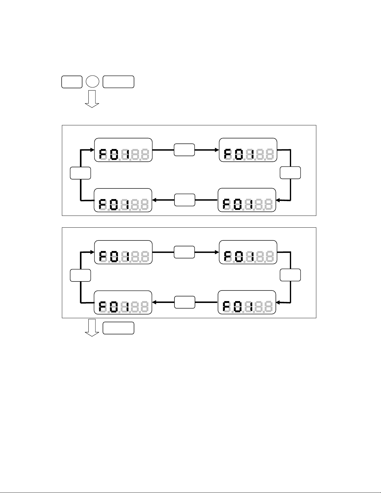
How to change value on the function selected?
To change the values of the function selected, use the Mode key button to scroll
through the options and the Zero/RST button to move to the next Mode.
Pressing the Mode button after setting the HI/LO limits exits out
of the function mode. You will need to reenter the settings to
change additional values.
5
Find Quality Products Online at: sales@GlobalTestSupply.com
www.GlobalTestSupply.com
Page 6
Operation diagram of how to access the Function Mode
Press and hold the Zero/RST key
Ncm
Kg
c
lb
i
Ncm
gcm
lbi
Turn OFF the TNP before starting
Power
Function Mode – Measurement unit
Zero/RST
TNP-2, 5, 10
Unit: N-m
Nm
Mode
Unit: lb-in
TNP-0.5
Unit: mN-m
mNm
Power on then release the Power button
but continue to hold Zero/RST key until display F01
Unit: N-c
Mode
m
Mode
Unit: Kg-cm
Mode
Unit: N-c
Mode
m
Mode
Unit: lb-in
Zero/RST
Mode
Pressing Zero/RST, it moves to the next function setting.
Unit: g-cm
Use the MODE key to change values of each function.
Use the Zero/RST key for moving to the next function
Mode
6
Find Quality Products Online at: sales@GlobalTestSupply.com
www.GlobalTestSupply.com
Page 7

02
Function Mode – Display (update rate)
f04
f04
1time/sec 2times/sec
f02
Zero/RST
Function Mode – Auto power OFF
Disable auto power OFF
f03
Mode
f02
Mode
4times/sec
f02
Mode
8times/sec
f02
Mode
Pressing Zero/RST, it moves to the next function setting.
Set auto power OFF to
10 minutes
Mode
Mode
f03
Zero/RST
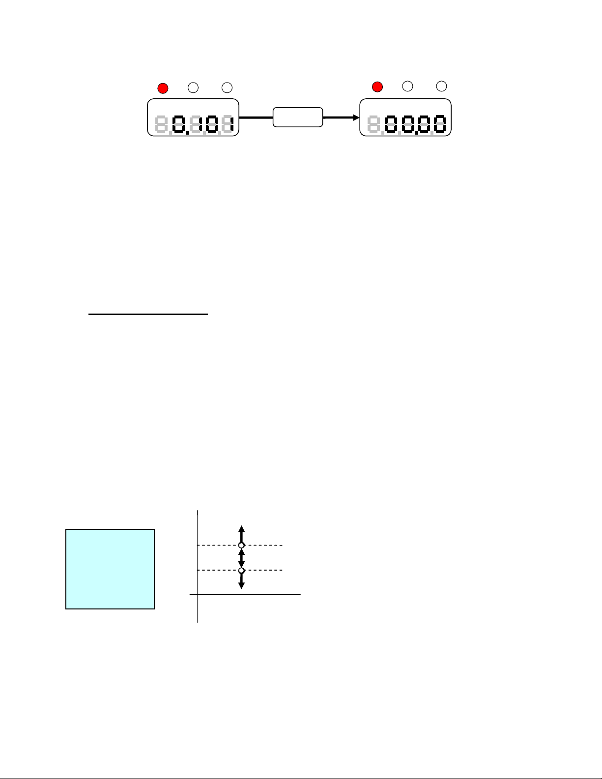
Function Mode – Sign Orientation
Open “+”
Zero/RST
Use the MODE key to change values of each function.
Use the Zero/RST key for moving to the next function
Pressing Zero/RST, it moves to the next function setting.
Open “-“
Mode
Mode
Pressing Zero/RST, it moves to the next function setting.
7
Find Quality Products Online at: sales@GlobalTestSupply.com
www.GlobalTestSupply.com
Page 8

Function Mode – Upper comparator value (Hi Limit)
Present upper value
HI
Recall
HI
Recall
Plus 1 by pressing
Recall key
HI
HI
Move to the right
Move to right side one by one by pressing
Mem key.
Zero/RST
Function Mode – Lower comparator value (Lo Limit)
Present lower value
Pressing Zero/RST, it moves to the next function setting.
LO
Key operation is the same in entering the Hi limit value.
Recall
Mem Mem
Move to the right
HI
Press Mem key scrolls back to
the 1st digit position,
Zero/RST
Move to setting register/ standard display
Use the MODE key to change values of each function.
Use the Zero/RST key for moving to the next function
8
Find Quality Products Online at: sales@GlobalTestSupply.com
www.GlobalTestSupply.com
Page 9

Operation
Pretest Checklist:
Determine the size of the sample to be tested. Adjust the 4 jig on the testing
table accordingly. Center the sample and use the knob to secure the sample in
place (clockwise to tighten the jig to the sample material).
It is important to make sure that all the jigs are flush to the moving brackets.
Each one of these jigs has set pins which slides into place inside the grooved
brackets.
Measuring Modes
Measuring Modes available on the TNP: OPEN, CLOSE, MEAN
Select the measuring mode required for testing. Please check the settings below
on how to select the right mode for testing.
Open mode
Open
Mean mode
Mean Close
Nm Nm Nm
Mode
Open
Mean Close
Mode
Mode
Close mode
Open
Mean Close
Pressing the Mode key toggles through the mode available from the TNP, LED
indicators are provided to display current selected mode.
OPEN and CLOSE modes are PEAK Values captured by the TNP, these values
are not real time values, and are retained on the display until one of the following
occurs, the Zero/RST key is pressed or a higher peak value is detected (which in
this case, replaces the current value detected).
9
Find Quality Products Online at: sales@GlobalTestSupply.com
www.GlobalTestSupply.com
Page 10
Open
Nm
Mean Close
Open
Mean Close
Nm
Zero/RST
Resetting the Peak values to Zero
MEAN is real time value based on the average data captured in 1000 samples
per second.
The maximum display update for all modes is 8 times/second.
This update rate can be adjusted by changing F02 from function mode
(See section - Values available 1, 2, 4, 8 times/second).
Comparator Function
This compares the measured value to the upper and lower limits entered under
function mode for HI and LO limits.
If both HI and LO limits are set to “0000” this feature is not available
(deactivated).
The following conditions are valid under comparator mode:
• HI>LO
• HI=LO (HI Red LED indicator will be lit on the Comparator LED indicators).
Utilizing this feature makes it an ideal tool for quality assurance checks.
Example: HI is set to 100 and LO is set to 50. Based from the conditions met
the corresponding LED will light up (HI (Red LED), GO (Green LED), LO (Red
LED)).
Test 1 = 105 HI
Red LED
Test 2 = 45 LO
Red LED
Test 3 =65, GO
Green LED
100 Upper limit value
50
0
HI:ON
OK:ON
Lower limit value
LO:ON
From the previous example any values greater than 100 will light up the HI red
LED.
Any values lower than 50 will light up the LO red LED.
Values measured in between these values (100<X<50) will give a GO green LED
indicator.
10
Find Quality Products Online at: sales@GlobalTestSupply.com
www.GlobalTestSupply.com
Page 11

How to change the HI and LO values from the TNP torque meter?
• To set the HI and LO limits from the TNP torque meter access the function
mode. (See Diagram How to Access the Function).
• Power off the torque meter
• Press and hold the Zero/RST key then power on the torque meter.
• Continue to hold on the Zero/RST key until the main display shows F01
• Press the Zero/RST key until the main display shows HI limit
• Using the Recall key we can increment the highlighted digit from 0-9.
• Press the Mem key to move from left to right or to the next digit.
• Entering values that are invalid the display will blink momentarily indicating
wrong values entered to the HI and LO limits. (HI>LO, HI=LO).
After entering the LO limit value and pressing the Zero/RST button the
torque tester will go back to normal operation.
11
Find Quality Products Online at: sales@GlobalTestSupply.com
www.GlobalTestSupply.com
Page 12
Zero adjustment / Tare the TNP
Taring or zeroing the value of the TNP initialize the torque meter to zero.
This function is performed by pressing Zero/RST button on the front panel. In
OPEN and CLOSE modes this zeros out the Peak values measured.
It is essential that the TNP be zeroed out before performing another
test. This ensures that the TNP is properly initialized and no
additional values are added to the measurement.
Saving Data in Memory
Data can be stored in the TNP meter by pressing the Mem key. This feature is
only available in OPEN and CLOSE measuring modes.
NOTE: In MEAN or Average mode the Mem key has no function.
“Open”or“Close”
measuring mode
Memory identification/Number
Memory registration
Mem
Nm
When the number of data points > 1000
After 1 sec, digits will return to original display.
001
Taking a closer look at display the upper sub-display indicates the
memory identification or data number.
001
Nm
After 1sec, the peak value displayed will
automatically reset to zero; ready for
another test.
Nm
12
Find Quality Products Online at: sales@GlobalTestSupply.com
www.GlobalTestSupply.com
Page 13

How to recall stored Memory
Select Open or Close Mode, press the Recall key and the display will indicate the
number of data stored in memory.
Press Recall key second time to access the following information.
• AVERAGE Value
• MAX Value
• MIN Value
• Stored data (Data order of recall is based from the last data stored in
memory)
Displays Max Values after pressing Recall
To access the stored measured value use the Recall key to scroll thru the values.
(This will be after the MIN value is displayed). The display will flash two sets of
numbers, the first number indicates the memory ID and the second number is the
value stored on that memory ID.
NOTE: The order of values is from the last data stored to the first data stored. To
review previous values shown, scroll through the values using the Recall key.
13
Find Quality Products Online at: sales@GlobalTestSupply.com
www.GlobalTestSupply.com
Page 14

Picture above indicates the memory ID followed by the stored data. Pressing the
Nm
Nm
(1sec interval)
Nm Nm
(1sec interval)
mode button anytime exits out of the memory window. Below is a flowchart of
how the recall function works.
Recall
Recall
Power
key
Recall
Last memory number, data display
Available Zero/RST key on main
display
CNT
Alternating
display
Recall
Average value
AVE
Minimum value
Test number displayed
CNT
Alternating
display
Recall
Recall
Maximum value
MAX
Recall
MIN
Recall
CNT
Alternating display:
(1sec.interval)
Shows last memory data
Returns to
measuring mode
Mode
Nm
14
Find Quality Products Online at: sales@GlobalTestSupply.com
www.GlobalTestSupply.com
Page 15

Clearing Stored Data
There are two types of memory clear available on the TNP torque meter.
• Single memory clear
• Clear all memory
Single Memory Clear
Single clear refers to erasing the stored data manually from the torque tester. The
erase process starts from the most recent to the very first data stored.
Clearing data that is within the set cannot be accomplished by a
single memory clear. The TNP does not allow the user to select the
memory to be deleted. (jump out of sequence).
How does it work?
First select from Open or Close Modes (Mean or average mode data cannot be
stored).
Press the Recall key to access memory, the first display you see will indicate the
number of data stored in the torque tester and the last value saved.
Example from the picture above shows 3 data is saved (003) and the last value is
12.6. Pressing the Zero/RST button, the last data is eliminated (CLr will appear
on the screen). Pressing the Zero/RST button again deletes the next data stored
in the TNP torque meter.
15
Find Quality Products Online at: sales@GlobalTestSupply.com
www.GlobalTestSupply.com
Page 16

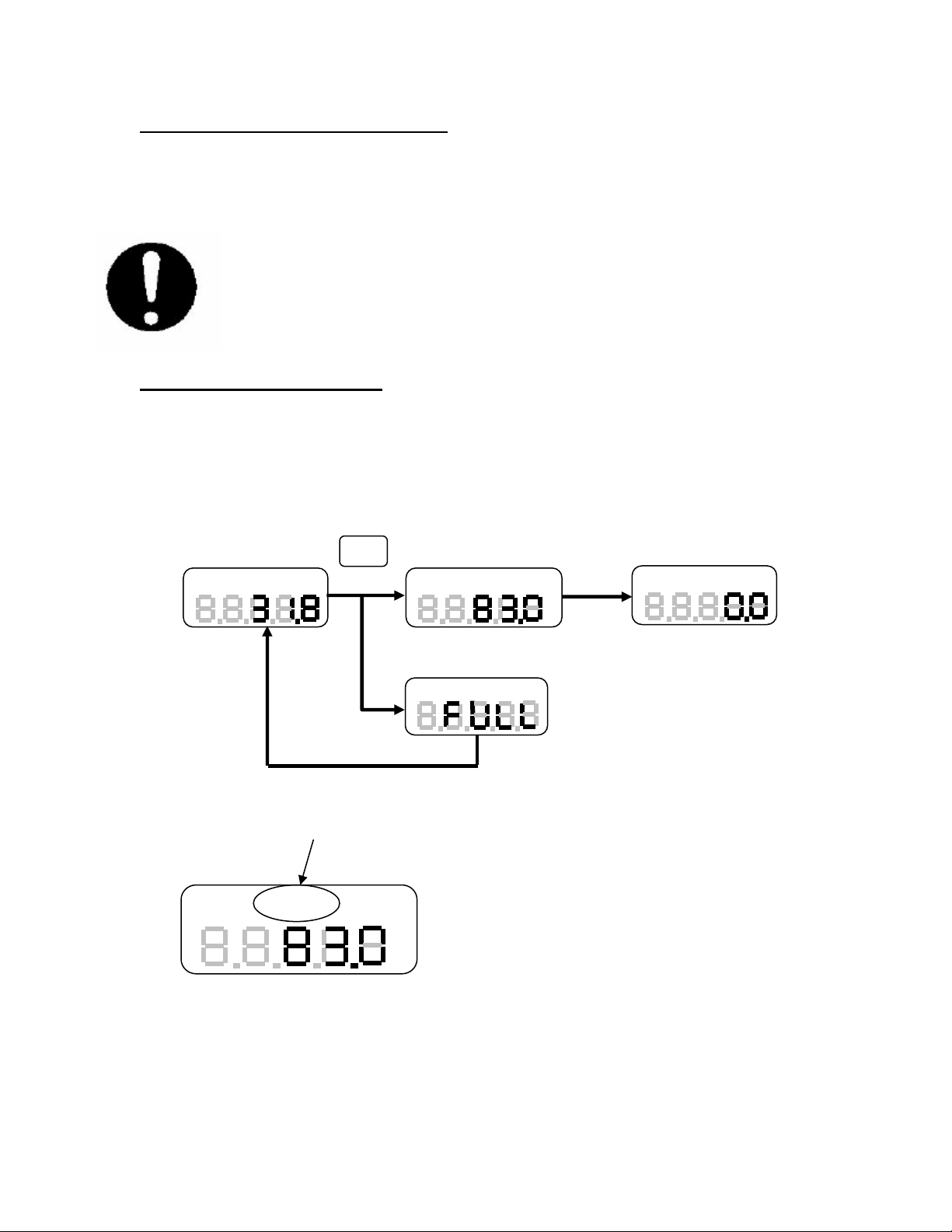
Here is a flowchart of how the single clear works.
002
Last memory number
Zero/RST
Clear
003
(Appear 1 sec.)
When there is one last data, the last data is cleared by pressing Zero/RST
key. After that, “nonE” is displayed at main display for 2 seconds, then the
display returns to measuring mode as shown below:
Last memory number
001
Zero/RST
No data
Back to standard
measuring mode
(Appear about 2 second)
After all the data are erased pressing the Zero/RST button returns the display to
normal measuring condition.
Clear all Memory
Clear all Memory or erasing all stored data in memory is possible by doing the
following.
• Power off the TNP torque meter
• Press the Mem key and continue to hold this key while powering the
torque tester. The TNP will initialize itself. You will see the model capacity
displayed on the front panel then followed by the message “nonE”. This
indicates that all data stored in memory have been erased or cleared.
Display shows no data
“Power”(off),
press “Mem” (hold “Mem” key),
press “Power” (on)
(Appear about 2 seconds)
Back to standard
measuring mode
16
Find Quality Products Online at: sales@GlobalTestSupply.com
www.GlobalTestSupply.com
Page 17

DIMENSIONS
17
Find Quality Products Online at: sales@GlobalTestSupply.com
www.GlobalTestSupply.com
 Loading...