

Page 1
ST-320BL LED Stroboscope Array
Operation Manual
Use in flammable environments is prohibited. Use in this manner may
result in fire or explosive.
Don’t look directly into the LED light Source. This may result in eye injury.
Don’t use or store in the following environments. Direct sunshine condensation, dust or caustic.
Do not alter, or modify of improperly. Such action may cause damage
and void warranty.
Operate with 0-35°C (32-95°F), 35-85% RH. Use outside of this range
may alter operation of the unit.
Case may become excessively hot when used continuously for more
than 2 hours. Mount unit on a tripod or other fixed device.
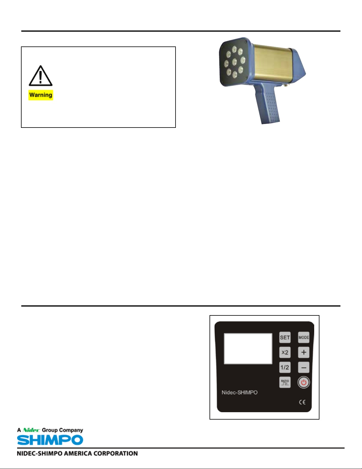
The ST-320BL is a portable or permanent mount
stroboscope. Utilizing super bright high-powered black light
LED lamps, these stroboscopes are perfect for UV ink printing
applications. The ST-320BL’s LED array provides a bright, stable
strobe light over a wide measurement range with a lifetime far
exceeding xenon lit stroboscopes. Operation is simple with the
8 button keypad and quick rate adjustment dial, combined with
large, backlit LCD display. Phase shift, flash duration, plus flash
rate are all quickly adjustable. The unit can work off user adjusted
flash frequency or from a remote sensor’s signal which will automatically adjust to corresponding process fluctuations.
The ST-320BL is designed for speed and frequency measurements in the printing, packaging, textile, automotive, cable, mining, steel, chemical, optical and medical industries in various applications.
SHIMPO INSTRUMENTS
SPECIFICATIONS
Flash Rate Range: 60 to 120,000 FPM ; 1-2000 Hz
Accuracy: 0.01%±1 digit of F.S. @ 77° F (25°C)
Lamp: 9 black light LED’s; 415 to 420 nm wave length.
Lamp Lifetime: Approximately 3~5 years depending on usage.
Display: Backlit LCD
Resolution: 60 ~12,000 FPM = 0.1 FPM; 12,001~120,000 FPM
= 1 FPM; 1~200 HZ = 0.01 Hz; 201~2000 = 0.1 Hz
Flash Duration: 0.1°- 2.5°
Phase Shift: 0-359°
Power Requirement: ST-320BL-1: 100-120 VAC; ST-320BL-2:
Rechargeable Battery.
Battery: (ST-320BL-2) Lithium DC 10.8V 2000mA
Battery Life: (ST-320BL-2): Approx. 12 hrs depending on settings
Input Signal: 12 V Pulse Input; Mini-USB.
Input Signal Range: 60-120,000 FPM (1-2000 Hz)
Input Pulse Width: Over 50 µs
Input Signal Flash Delay: 0-999 ms; 0-359°
Temperature Limits: 32-95°F (0-35°C)
Humidity Limits: 35 to 85% RH
Enclosure: Aluminum & ABS
Mounting: 1/4-20 UNC Thread
Enclosure Rating: IP54
Product Weight: ST-320BL-1: 1.85 lb (0.84 kg);
ST-320BL-2: 1.98 lb (0.90 kg)
Package Weight: ST-320BL-1: 4.40 lb (2.0 kg);
ST-320BL-2: 5.73 lb (2.6 kg)
Approvals: CE
Warranty: 1 year
Included Accessories: Carrying Case, ST-320BL-1: 6.5’ (2 m)
AC power cord; ST-320BL-2: Power Recharging Adapter with cord.
Operation Panel Located on Control Enclosure
POWER: Power on and off.
MODE: Select mode of operation or Parameter Menu: Internal/
External/Parameter Settings
SET: Change Units (FPM to Hz); In Parameter Menu scroll through
parameter settings, Store setting values.
x2: Multiplies the flash rate/frequency by a factor of 2.
1/2: Divides the flash rate/frequency by a factor of 2.
RATIO: Adjusts flash duration (flash pulse width) in Internal/Ex-
ternal modes.
“+”: Advance image forward 3 degrees at a time in internal mode.
In parameter setting mode, adjusts setting values.
“-”: Retard image backwards 3 degrees at a time in internal mode.
In parameter setting mode, adjusts setting values.
Dial: Set flash rate or frequency. CW: Increase flash rate/frequen-
cy. CCW: Decrease flash rate/frequency. (Turn dial quickly to
drastically change value; Turn dial slowly to change value by 1
digit.) In parameter setting mode, CW or CCW rotation changes the setting value. *Dial located on side of unit.
Page 2
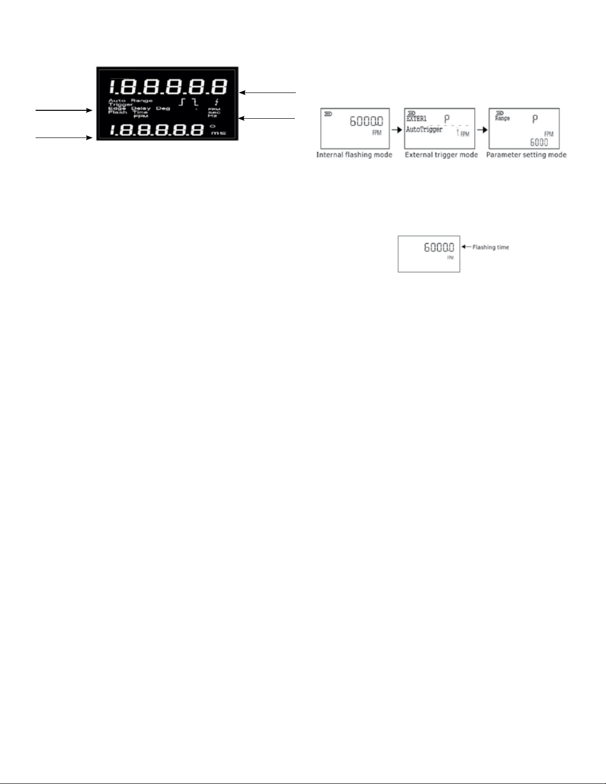
LCD Display
Display
Parameter
Icons
Sub
Data Display
Main Data Display
•Flash rate value will be displayed in internal flashing or External trigger mode.
Units
Main
Data
FUNCTION INSTRUCTIONS
Mode Selection - To switch between INTERNAL, EXTERNAL and
PARAMETER menu, press and release the MODE key. For details
about Parameter setting mode, please refer to Parameter setting
menu section.
•Display will indicate “P” or “LCD” (in ON/OFF setting of LCD
backlight) in *Parameter setting mode.
*For details about Parameter setting mode, please refer to Parameter setting mode.
Sub Data Display
Internal Mode
•Phase Shift will indicate degrees of phase shift in internal flashing mode. To change the degrees of phase shift, press + or keys. The display will reflect the cumulative angle of phase shift.
•The flash duration time will be displayed when the RATIO key
is pressed. The flash duration time can then be increased or
decreased with the dial from 0 to 2.5 (0~2.5°) degrees.
External Mode
• In external trigger mode, the display will show the settings of
delay time. For details about changing these settings, please
see external trigger mode section.
Internal Flashing Mode
Changing Units of Measure in Internal Mode - To change the
measuring units from FPM to Hz, press and release the SET key.
Units will alternate with each press and release.
Flash Rate (Frequency Setting) in Internal Mode You can set the flash rate by turning the dial in the center of the
unit. To increase the flash rate, turn the dial in the clockwise direction. To decrease the flash rate, turn the dial in the counter-clockwise direction. For small adjustments, turn the dial slowly. For
quick adjustments, rotate the dial quickly. The flash rate range
and resolution will be different according to the selected measuring range.
One function of a stroboscope is to provide a “stopped” image
of a rotating target when the flash rate of the stroboscope has
matched the rotational speed of the target object. The stroboscope will show a single image when the flash rate is set to a
lesser multiple of the true RPM (1/2,1/3,etc.) When the flash rate
is increased to a higher multiple (2,3,etc.), multiple images will
appear. To find the true RPM of the target object, reduce the flash
rate to a lower multiple until only one image appears.
2
Page 3

Stopped Image:
1/3
Example
True
Rotational Speed
of Target Object
(rpm)
900 rpm
Flash Rate of
Stroboscope
(fpm)
3600
2700
1800
900
450
300
Multiple
of True
Rotational
Speed
4 times
3 times
2 times
1 time
1/2 times
1/3 times
Number of
Stopped
Images
4
3
2
1
1
1
Multiple/Divide by 2 Function - The flash rate can be doubled or
halved by x2 and 1/2 keys on the operation panel.
1. Doubling the flash rate(x2) Press x2 key to multiply the current flash rate by a factor 2.
Flash Duration (Brightness) Settings
The flash duration, RATIO key, can be set within the range of 0.1°-
2.5° over a 360° period with a resolution of 0.1°.
When the flash duration is lengthened, the brightness of the flash
will be increased, however the image of the target object may
appear slightly out of focus. When the flash duration is shortened,
the brightness will be decreased, yet the image of the target object will become more focused.
To change the flash duration in either Internal or External modes,
first press the “RATIO” key. Once pressed, “Flash Time” will appear with the current flash pulse duration ratio in the sub display.
The flash pulse duration can now be modified.
Note: The use of the x2 key will have no effect when multipli-
cation of the current flash would result in a value that exceeds
the maximum flash rate range. After the flash rate changes, it
becomes the new value based on the set display resolution.
Therefore, the rate may likely not return to the original frequency, even if the “1/2” key is pressed.
2. Having the flash rate(1/2) Press “1/2” key to divide the current flash rate by a factor of 2. Operation Indication
Note: The use of the 1/2 key will have no effect when the division of the current flash rate would result in a value that goes
below the minimum flash rate.
After the flash rate changes, it becomes the value based on the
set display resolution. Therefore, the rate may likely not return
to the original, even after pressing the x2 key.
Phase Shift (Angle) - First, press ‘SET” key, then enter this
mode. When the rotation speed of the target object and the
flash rate of the ST-320BL becomes equal, the phase shift
function can be used to delay the flash so that the image will
appear to rotate incrementally. The phase shift angle can be
increased or decreased 3°, each time the “+” or “-” keys are
pressed or the adjustment dial is turned CW or CCW. The sub
display will show the cumulative angle of the phase shift.
To set the flash pulse duration while in the modifiable mode;
press “+” key, or turn the dial in the clockwise direction to increase the flash pulse duration by 0.1° increments.
Press “-” key, or turn the dial in the counter clockwise direction to
decrease the flash pulse duration by 0.1° increments.
3
Page 4

External Trigger Mode
External trigger mode will allow the flash rate of the ST-320BL
stroboscope to be controlled by an external signal, such that the
flash rate will automatically increase or decrease when the signal
is altered, so that it may remain in unison with the speed of a
changing target.
Connector of External Input/Output
1. Power: Charging round socket: Positive 16V,
Negative 16V
2. External Synchronous Output:
Connector: Mini-USB Port:
1.+12V output
2. Out: External Pulse Output to sync other
ST-320BL’s
3.-12V output
3. External Pulse Input from Sensor:
Connector: Mini-USB Port
1.+12V output
2. Input: external pulse Input from sensor
3.-12V output
j k l
Input Signal Characteristics:
Input frequency: 60-12,000 fpm (1-2000Hz) Input pulse width:
over 50 µs.
Delay angle: 0-359° (every 1°) Delay time: 0-999 ms (every 1ms)
Note: When the external sensor is used, use the AC power
adapter power supply to ensure proper sensor performance
External Trigger Mode: LCD Display Information
The frequency of the external signal is measured each period,
while the latest external frequency measurement is updated every 50 ms.
External Trigger Flash Delay Setting
A flash angle delay can be programmed into the ST-320BL to delay the flash after an external trigger signal is detected. The unit of
delay can be set to time (msec) or degree (°). Use “+” or “-”key to
alternate between the settings of delay angle or delay time.
+
_
Delay Time Setting
The delay time can be set to incorporate a delay from the external
pulse input to the flash output. The delay can be set from 0-999
ms with a resolution of 1 ms.
Note: Because of the existence of a delay in internal calculation,
the ST-320BL flashes 60 µs after the external signal input. This
results in the actual setting delay time having approximately +60
µs added to the delay.
Example
Trigger: positive edge Delay Time: 10 ms
The ST-320BL does not flash at the 1st trigger pulse as shown
below in the diagram, ST-320BL flashes from the external trigger
after 10 ms.
Additionally, there are several settings that can be adjusted in External Trigger mode, including phase shift, delay time, and flash
duration.
The flash timing can be set by using the positive or negative edge
of an external trigger signal. Also the delay of the flash timing can
be set by time in (msec) or degrees (°).
Press “mode” once and the unit enters EXTER 1. In this mode,
frequency (HZ) or speed (FPM) automatically flash according to
the external trigger signal.
After setting the parameters, generally the detected object has an
advanced or lag phenomenon. To adjust, press the “+” or “-” for
fine-tuning, change the perimeter parameters, so that detected
object achieves a still image. In this setting process, the unit will
automatically save the last setting.
4
Page 5

If the period of the external input is less than the setting of the
delay time, the delay time is ignored and the ST-320BL flashes as
if the delayed time equals 0.
To adjust the delay time, press the “+” or “-” key. Or turn the dial
to set the delay time. Delay time will increase as the dial is turned
clockwise, and decrease as it is turned counter clockwise.
Delay Angle Setting
As the period of the external input is 360, the delay angle can be
set from 0°to 360°, by every 3°. Since the internal calculation time
is 60 µs, the actual delay time is as follows:
Delay angle setting/360° x period of external input + appox. 60 µs.
The ST-320BL does not flash at the 1st trigger pulse as shown
below in the diagram.
Example: Trigger: positive Delay Angle: 36° 36/360=10
Parameter Settings
To enter parameter setting menu, press “MODE” until the LCD displays “P”. When the display shows “P’, press the SET key to cycle
between the various parameter settings available (range, trigger
edge, delay time, LCD backlight, Auto Shut-off, Initial). To store
the settings and return to measuring modes, press the MODE key.
Measuring Range Setting
You can adjust the flash setting from the home view and also in
parameter mode if desired.
Trigger Edge Setting (External Modes)
In external mode, the trigger edge parameter will allow for selecting either the leading edge or trailing edge of the input pulse to
trigger the stroboscope flash.
In parameter mode, use the SET key to cycle to the Trigger Edge
setting parameter mode. To set the trigger edge as “Down Edge”
(trailing), press “ -“ key or turn the dial clockwise. To set the trigger edge as “Up Edge” (leading), press “+” key or turn the dial
clockwise.
If the current period of external trigger input changes, the time of
the flash is not accurate, because the time is calculated based on
the previous measurement period.
If the current period of external trigger input is less than the previous period and the next trigger input occurs before the flash time,
the delay angle setting is ignored and the ST-320BL flashes at the
delay angle=0°.
To adjust, press the “+” or “-” key. You may also use the adjustment dial.
The delay angle increases as the dial is rotated to the right. The
angle settings will go to 0° as the angle increases past 359°.
Delay angle decreases as the dial is rotated to the left. The settings will eventually go to 0° as the angle decreases past 359°.
When trigger edge setting is set to “up edge”. The flash will occur on the leading edge of the input pulse (when delay setting is
zero).
External Pulse Signal from Machine/Sensor
vs. Stroboscope Flash
Up Edge
When trigger edge setting is set to “down edge”. The flash will
occur on the trailing edge of the input pulse (when delay setting
is zero).
External Pulse Signal from Machine/Sensor
vs. Stroboscope Flash
Down Edge
5
Page 6

Back Light Setting
The LCD display of the ST-320BL stroboscope has a backlight
that can be turned on or off in the parameter settings. Turning off
the backlight will conserve battery power. To adjust the backlight
setting, enter parameter mode and use the “SET” key to cycle to
LCD setting. Press “+” key to turn on the backlight. Press “-” key
to turn off the backlight.
Note: If the backlight is set to on, as a power saving feature, it will
automatically shut off after the set minutes if no keypad or dial
operation has occurred. The LCD backlight will turn back on with
keypad or dial operation.
Automatic Power-Saving Settings
Auto Power Off: The unit will automatically turn off after 1 to
1000 minutes depending on settings if no keypad or dial operation occurs when using battery power. Flashing will resume
with either a dial (rotation) movement or a keypad operation.
The LED auto shutoff will not occur in External trigger mode,
while a signal is being received by the unit. The LED flashing
will automatically turn off after the set 2 minutes of no external
pulse input.
LCD Back Light Off: If the backlight is set to on, as a power
saving feature, it can be adjusted to automatically shut off from
1 to 1000 seconds, if no keypad or dial operation has occurred.
The LCD backlight will turn back on with keypad or dial operation.
Mounting
To mount permanently, remove the two screws holding the trigger
handle. The threaded adapter will now be visible. Discard screws
and handle. With appropriate 1/4-20 UNC male thread connection, attach to stroboscope’s female threaded adapter. Hand tighten to secure.
Factory Reset (Initial)
To reset unit to factory values choose “Yes” under Initial in the
parameter setting mode. Then press “SET”.
 Loading...