

SHIMPO Instruments FG-7005-NIST, FG-7006-NIST, FG-7002-NIST, FG-7007-NIST, FG-7003-NIST User manual
...Page 1

FG-7000 Digital Force Gauge
Operation Manual
Operators should wear protection such as a mask and gloves in case
pieces or components break away from the unit under test.
Whether the unit is ON or OFF, DO NOT exceed the capacity of the
gauge. NEVER exceed 150% of the rated capacity, or the load cell will
be damaged. At 110% of the rated capacity, the display will flash a
warning.
When mounting FG-7000 Series Digital Force Gauges, use M6 mounting screws with a maximum insertion depth of 7 mm into the gauge.
Hand tightens mounting screws, DO NOT use tools. Do not use damaged clamp.
Measure in line tension and compression forces only. DO NOT attempt
to measure forces at an angle to the measuring shaft – damage to load
cell and/or shaft may result.
Do not attempt to repair or alter this instrument. Warranty will be voided
and damage to the unit may result.
Use and store within the stated temperature and humidity ranges, or
damage and failure may result.
If not using this instrument for extended periods of time, remove the
batteries to prevent potential battery leakage from causing product
damage.
The new FG-7000 Series digital force gauges are loaded with functionality to simplify your compression and tension testing needs.
Their robust housings are designed to fit perfectly in the hand for
portable testing. The large backlit, 180° auto-reversible display,
compression/tension icons, combined with the dual labeled key
pad allows for instant switching from push to pull testing for portable or test stand applications.
The multiple-language FG-7000’s provide menu programming for
easy selection and set-up of the instrument to your desired requirements. Three modes of operation are selectable: Track mode
for live readings, Peak mode for displaying the peak reading that
remains until a higher peak is sensed, and Auto Peak mode which
is similar to Peak mode except the peak on the display will additionally reset after a programmed time period. Programmable
limits provide a quick visual and audible indication if a test passed
or failed on the LCD. In addition, the comparator output can be
set up for integration of the instrument into your quality system for
repetitive testing such as on a production line.
These high-tech instruments can easily data log a reading at the
push of a button for simple data acquisition, or be set to continuous data storage. Data can be viewed on the screen, sent to the
optional printer, or loaded to be analyzed and graphed on the free
software program. The 1,000 point memory with programmable
groups allows for multiple tests to be recorded and easily sepa-
rated upon loading.
SPECIFICATIONS
Accuracy: ± 0.2% F.S.
Selectable Units: mN, N, gf, kgf, ozf, and lbf. (Depending on
Range)
Overload Capacity: 150% of F.S. (LCD flashes beyond 110% of
F.S.)
Measurement method: Peak, Autopeak or Track Mode
Data Sampling Rate: 1000 Hz
Display: 160*128 dot matrix LCD with LED Backlight
Display Update Rate: 10 times/second
Resolution: (See 5.2 chart)
Memory: 1000 data
Set Point: Programmable high and low limits
Battery Indicator: Display flashes battery icon when battery is
low
Power: 3.6VDC 800mAH Ni-MH rechargeable batteries
Battery Life: Approximately 16 hours continuous use per full
charge
Charger / Adaptor: Universal USB/BM charger, Input: 110 ~
240VAC
Temperature Effects: <0.054% per °F (0.03% FS per °C)
Outputs: RS-232; low limit and high limit outputs
Operating Temperature: 14 to 104°F (-10 to 40°C)
Storage Relative Humidity: 20 to 80%
Housing: Aluminum
Storage Temperature: -4 to 122°F (-20 to 50°C)
Oper. Relative Humidity: 5 to 95%
Dimensions: 5.7 x 2.9 x 1.4” (145 x 73 x 35.5 mm)
Product Weight: 1.5 lb (0.7 kg)
Package Weight: 2.8 lb (1.3 kg)
Warranty: 1 year
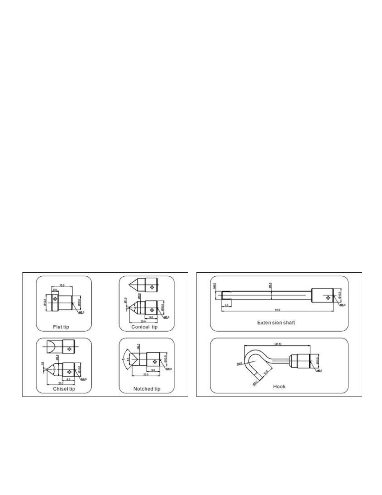
Included Accessories: AC Adaptor/Charger, USB cable, calibra-
tion cert., 6 attachments: hook, flat tip, conical tip, chisel tip,
notched tip, extension shaft.
LCD Screen
1. Battery icon: Battery level or charging status. Flashes when
gauge needs to be recharged.
2. OK/OV Indicator: under lower limit; between low limit
and upper limit; over upper limit
3. Force icon: Indicates force direction. means tension
means compression
4. Test mode icon: Three measurement modes: Track, Peak
and Auto Peak.
5. Current meaured value
6. Analog bar: Indicates current position within full scale. When
the bar enters the area enclosed by the dotted line, it means
full scale capacity is exceeded and overload.
7. Storage icon: Indicates data is being saved.
8. System time
9. Units Indicator: Selected engineering unit.
Find Quality Products Online at: sales@GlobalTestSupply.com
www.GlobalTestSupply.com
Page 2
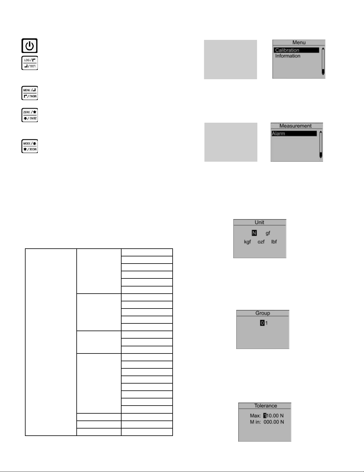
1.3 Key Functions
All keys are capacitive touch.
ON/OFF: Push for 2 seconds to power On or Off
During Measurement: Print the current force value or
store data, depending on the key setting. (See 2.5.7 for
key setting)
In Menus: Back or quit.
From the home screen, touch “MENU” to enter the main menu.
(Figure 2-1)
During Measurement: Enter the menus.
In Menus: Select or Enter
During Measurement: Track mode, tares weight of
attachment. In Peak & Auto Peak modes, resets the
peak value.
In Menus: Moves selection up or increases the value.
During Measurement: Changes the measure mode from
Track, Peak or Auto Peak
In Menus: Moves selection down or decreases the
value.
1.4 Modes
Track: Real time, live measuring mode.
Peak: Peak readings will not changed until a higher value is mea-
sured.
Auto Peak: When the Peak Time is up, resets the peak value automatically. (See 2.2.4 for Peak Time.)
2. ADVANCED MENU OPTIONS
2.1 Menu Structure
The FG-7000 Series Force Gauge has multi-level menu interface
(Table 2-1) that enables simple navigation and programming.
Unit
Group
olerance
T
Test Mode
Peak Time
Alarm
Storage Mode
Browse All
Browse Selected
Delete Selected
Delete All
Print Recent
Print Selected
Print All
Display Mode
Power Off
Backlight
Key Tone
Date/Time
Password
Key Setting
Default Setting
Menu
Measurement
Memory
Printing
System
Language
Calibration
Information
Figure 2-1a Figure 2-1b
2.2 Measurement
The Measurement menu contains six selectable items: Unit,
Group, Tolerance, Peak Time and Alarm. (Figure 2-3)
Figure 2-3a Figure 2-3b
2.2.1 Unit
The measuring unit can be selected under this menu. Different range models may have different unit selection capabilities. Touch “ZERO” or “MENU” keys to shift to the next selection. Press “LOG” to cancel or touch “MENU” to confirm and
exit. (Figure 2-4)
Figure 2-4
2.2.2 Group
When several test samples need to be measured, the samples can be coded into groups. The range is 01-99. When set
to “00”, become, “01” automatically. Press “ZERO” to adjust
the value, touch “MODE” to shift to the next position. Touch
“LOG” to cancel; press “MENU” to confirm and exit. (Figure
2-5)
Figure 2-5
2.2.3 Tolerance
In the Tolerance menu, program high and low limit values to
enable ok/ov testing. The lower limit value cannot be greater
than the upper limit value, and neither limit value can be greater than 110% of the rated capacity. Press “ZERO” to adjust the
value, touch “MODE” to shift to the next position. Press “LOG”
to cancel; touch “MENU” to confirm and exit. (Figure 2-6)
Table 2-1
Figure 2-6
2
Find Quality Products Online at: sales@GlobalTestSupply.com
www.GlobalTestSupply.com
Page 3

2.2.4 Test Mode
Change the mode of operation between three modes, press
“ZERO” or “MODE” keys to select. Press “LOG” to cancel
or “MENU” to confirm and exit. This adjustment can also
be changed at home screen display by simply pressing
“MODE”.
Figure 2-7
2.2.5 Peak Time
In the Peak Time menu, the peak auto reset time can be set.
The range is 1-99 seconds. Touch “ZERO” to adjust the value,
press “MODE” to shift to the next position. Press “LOG” to cancel; touch “MENU” to confirm and exit. (Figure 2-8)
Figure 2-8
2.2.6 Alarm
The alarm function can be turned on or off. Touch “ZERO” or
“MODE” keys to shift to the next position. Press “LOG” to cancel, touch “MENU” to confirm and exit. (Figure 2-9)
Figure 2-11 Figure 2-12
2.3.2 Browse All
The data will be displayed. Touch “ZERO” or “MODE” keys to
shift to the next position. Touch “MENU” to see Delete
or Print options. Touch “LOG” to go back. (Fig. 2-13)
j Position number
k Data and units
l Force Direction
m First Position Data
Figure 2-13
2.3.4 Browse Selected
User can choose the data to browse. The available range of
data stored is shown. Touch “ZERO” to adjust the value. Press
“MODE” to shift to the next position. Press “LOG” to cancel;
touch “MENU” to confirm. (Figure 2-14)
m
j k
l
Figure 2-9
2.3 Memory
In the Memory menu, the user can select the mode of data storage, browse, delete, or print the data. (Figure 2-10)
Figure 2-10
2.3.1 Storage Mode
Two storage modes can be selected in this menu: Single and
Series. Touch “ZERO” or “MODE” keys to select between the
two. Press “LOG” to cancel; touch “MENU” to confirm and exit.
(Figure 2-11)
Single: At the home screen, pressing the “LOG” stores the current displayed value. (If the default settings key is for storage.
See 2.5.7 key setting.)
Series: Continuous data logging will only operate while in the
Auto Peak measuring mode. When the peak time has expired,
unit stores the current displayed peak value and then resets
the peak value on the display. Touch “LOG” to start, touch
“LOG” again to end. (Figure 2-12)
Figure 2-14
2.3.5 Delete Selected
Select the range of data to be deleted. Touch “ZERO” to adjust
the value. Press “MODE” to shift to the next position. Touch
“LOG” to cancel; touch “MENU” to confirm. (Figure 2-15)
Figure 2-15
2.3.6 Delete All
In this menu, a prompt will appear. All data will be deleted by
selecting “YES” and cancelled by selecting “NO” or pressing
“LOG”. (Figure 2-16)
Figure 2-16
3
Find Quality Products Online at: sales@GlobalTestSupply.com
www.GlobalTestSupply.com
Page 4

2.4 Printing
The Printing menu contains three selectable items: Print Recent,
Print Selected and Print All. (Figure 2-17) The data saved in memory can be output to a printer through the serial port RS232 connection. (See 4.2.1 RS232 for more information) An example test
report is shown in Figure 2-18.
2.5.1 Display Mode
Select the mode of the LCD display: Automatic, Obverse and
Reverse. Touch “ZERO” or “MODE” keys to shift to the next
position. Press “LOG” to cancel; Push “MENU” to confirm and
exit. (Figure 2-23)
Figure 2-17 Figure 2-18
2.4.1 Print Recent
Print recently stored data in this menu. The range is 0~19. (Figure 2-19) Touch “ZERO” to adjust the value. Touch “MODE”
to shift to the next position. Press “LOG” to cancel. Press
“MENU” to confirm.
Figure 2-19
2.4.2 Print Selected
In this menu, select the data range to print. Touch “ZERO” to
adjust the value, touch “MODE” to shift to the next position.
Press “LOG” to cancel; touch “MENU” to confirm. (Figure 2-
20)
2.5.2 Power Off
To maximize battery life, the power can be set to shutdown
after non-use. The time can be set in this menu. The range is
01-99 minutes. When set to “99” the gauge will never turn off.
Touch “ZERO” to adjust the value, touch “MODE” to shift to the
next position. Press “LOG” to cancel; Push “MENU” to confirm
and exit. (Figure 2-24)
Figure 2-24
2.5.3 Backlight
Under this menu, the backlight can be set to ON, OFF or have
an auto shutdown. Touch “ZERO” or “MODE” keys to shift to
the next position. Press “LOG” to cancel. Press “MENU” to
confirm and exit. (Figure 2-25)
Figure 2-23
Figure 2-20
2.4.3 Print All
To print all data saved in memory, a prompt window will display. All data will be printed by selecting “YES”. This operation
will be canceled by selecting “NO” or touching “LOG”. (Figure
2-21)
Figure 2-21
2.5 System
Under the System menu, several parameters may be set per Figure 2-22.
Figure 2-22a Figure 2-22b
4
Figure 2-25
2.5.4 Key Tone
Turn the key sound ON or OFF. Touch “ZERO” or “MODE”
keys to shift to the next position. Touch “LOG” to cancel; Press
“MENU” to confirm and exit. (Figure 2-26)
2.5.5 Date/Time
The system time may be set under this menu. Touch “ZERO”
to adjust the value. Press “MODE” to shift to the next position.
Touch “LOG” to cancel. Press “MENU” to confirm and exit.
(Figure 2-27)
Figure 2-26
Figure 2-27
Find Quality Products Online at: sales@GlobalTestSupply.com
www.GlobalTestSupply.com
Page 5
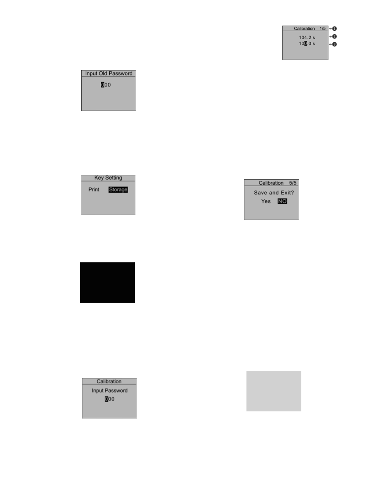
2.5.6 Password
The system password can be changed. First, enter the old
password, then enter the new password and confirm the
new password. The default System password is “123”. Touch
“ZERO” to adjust the value. Press “MODE” to shift to the next
position. Touch “LOG” to cancel; Push “MENU” to confirm and
exit. (Figure 2-28)
2.5.7 Key Setting
Set the default function of the “LOG” key from the home
screen. The function can be set to print or store the current
displayed value. Press “ZERO” or “MODE” to select the proper
setting. Press “LOG” to cancel; touch “MENU” to confirm and
exit. (Figure 2-29)
Figure 2-28
jCalibration Point
kCurrent Value
lStandard Input Value
Figure 2-32
Load a standard force on the gauge. Wait a moment for the force
to stabilize. The current value (2) should equal the standard force
applied.
If the values do not match, press “ZERO” and “MODE” keys to
correct the standard input value (3).
Press “MENU” to enter the next calibration point. After any of the
calibration points have been completed, touch “LOG” to exit the
calibration mode. Then save the calibration or discard by pressing
“Yes” or “No”.
After completing the calibration of the 5th point, the confirmation window will automatically ask to “Save and Exit” by selecting
“Yes” or “No”. (Figure 2-33)
2.5.8 Default Setting
If you make a selection that you feel has caused the gauge to
operate improperly, you can restore it to the factory default settings. Carefully use this function! (Figure 2-30)
Figure 2-29
Figure 2-30
2.6 Calibration
Users can field-calibrate the gauge. First, enter the system password (Default is 123) by pressing the “ZERO” and “MODE” keys.
Then press “MENU” to confirm. (Figure 2-31)
Press “ZERO” or “MODE” to select, then press “MENU”. If “Yes”
is selected, “Calibration Complete!” is displayed.
NOTE:
1. Ensure that the tare of attachment has been cleared before
calibration.
2. For higher measuring precision throughout the test range,
calibrating a point with a force at full scale is recommended.
3. Compression and tension calibrations are saved separately.
The force gauge can identify the direction of the force, but each
must be completed in a separate procedure.
Figure 2-33
2.7 Information
Information includes the model, version of the software and the
serial number. (Figure 2-34)
Figure 2-31
Find Quality Products Online at: sales@GlobalTestSupply.com
www.GlobalTestSupply.com
Figure 2-34
5
Page 6

3. CHARGING
The FG-7000 Series Digital Force Gauge is supplied with a set of 3
Nickel Metal Hydride AAA rechargeable batteries, which are supplied fully charged to allow immediate use. Users need to recharge
batteries when a low battery icon flashes. Users should connect
the gauge and the charger using the USB cable. Then connect
the charger to an AC socket to start charging. Laptops and other
USB devices can also charge the gauge. A fully charged battery
pack will provide approximately 16 hours of constant use.
Rechargeable battery pack:
- Type: Ni-MH 3.6VDC 800mAH rechargeable batteries
-Charging time: approx. 3~4 hours
-Battery life: approx. charge and discharge 500 times
4. COMMUNICATIONS
4.1 USB
The FG-7000 Series Digital Force Gauge is designed in accordance with USB2.0 standard protocol. (Figure 4.1) The USB Port
can be connected to a charger with the USB cable for charging
the internal Ni-MH battery and can be connected to a computer
for uploading the measured values. Connect the gauge and the
computer with the USB cable, then open the computer software.
Upload the values. Please refer to the software manual for additional information.
4.2.1 RS232
The RS232 serial port is used to connect a printer to print the
memory data.
RS-232 specifications are as follows:
-Data transmission: serial interface
-Synchronization: asynchronous
-Signal Level: RS-232 level, logic 1:-5v, logic 0: +5v
-Hardware Flow Control: None
-Data word length: 8 bits
-Stop bit: 1bit
-Parity: None
-Baud rate: 38400
4.2.2 Comparison Output
Comparison Output internal circuit shown as Figure 4-3.
4.2 Port Pin Assignments
PIN# Definition
1 RS232-Transmit
2 RS232-Receive
3 RS232-Ground
4 Comparison Output B
5 Reserved
6 Comparison Output C
7 Comparison Output A
8 Reserved
Table 4-1
Figure 4-1
Figure 4-3
When the measured value is less than the lower limit tolerance
value, the “pc2” operates, 7pin and 6pin line conduction. When
the measured value is more than the upper limit tolerance value
or 110% of the rated capacity, the “pc1” operates, 4pin and 6pin
line conduction. Maximum permissible voltage: 7pin to 6pin, 4pin
to 6pin 35V; 6pin to 7pin, 6pin to 4pin 6V.
5. MISC.
5.1 Accessories
6
Find Quality Products Online at: sales@GlobalTestSupply.com
www.GlobalTestSupply.com
Page 7
5.2 Capacity and Resolution
Model mN N gf kgf ozf lbf
FG-7001
FG-7002
FG-7003
FG-7004
Fg-7005
FG-7006
FG-7007
FG-7008
FG-7009
Capacity 2000.0 2.0000 200.00 - 7.000 -
Resolution 0.5 0.0005 0.05 - 0.001 -
Capacity 5000.0 5.0000 500.00 - 18.000 1.1000
Resolution 0.5 0.0005 0.05 - 0.005 0.0001
Capacity 10000 10.000 1000.0 1.0000 35.00 2.2000
Resolution 1 0.001 0.1 0.0001 0.01 0.0005
Capacity 20000 20.000 2000.0 2.0000 70.00 4.400
Resolution 5 0.005 0.5 0.0005 0.01 0.001
Capacity 50000 50.000 5000.0 5.0000 180.00 11.000
Resolution 5 0.005 0.5 0.0005 0.05 0.001
Capacity - 100.00 10000 10.000 350.0 22.000
Resolution - 0.01 1 0.001 0.1 0.005
Capacity - 200.00 20000 20.000 700.0 44.00
Resolution - 0.05 5 0.005 0.1 0.01
Capacity - 500.00 50.000 50.000 1800.0 110.00
Resolution - 0.05 0.005 0.005 0.5 0.01
Capacity - 1000.0 100.00 100.00 3500 220.00
Resolution - 0.1 0.01 0.01 1 0.05
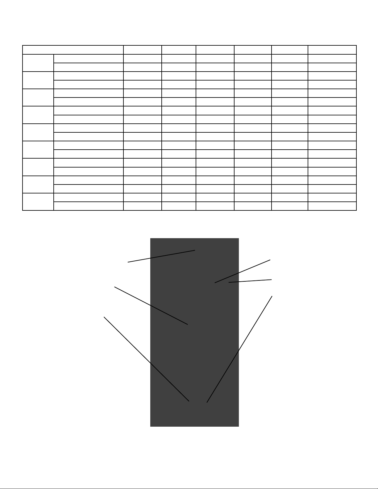
5.3 Diagram
Measuring Shaft:
Tension or compression forces.
Capacitive Touch Keys
(See Key Function)
USB Port: Recharge the internal
Ni-MH battery or connect to PC
160*128 Dots LCD
(See LCD Screen)
Robust Metal Housing
Communications Port
(See Figure 4-2)
7
Find Quality Products Online at: sales@GlobalTestSupply.com
www.GlobalTestSupply.com
Page 8
5.4 Dimensions
Find Quality Products Online at: sales@GlobalTestSupply.com
www.GlobalTestSupply.com
 Loading...