

Page 1
EDMS
Operation Manual
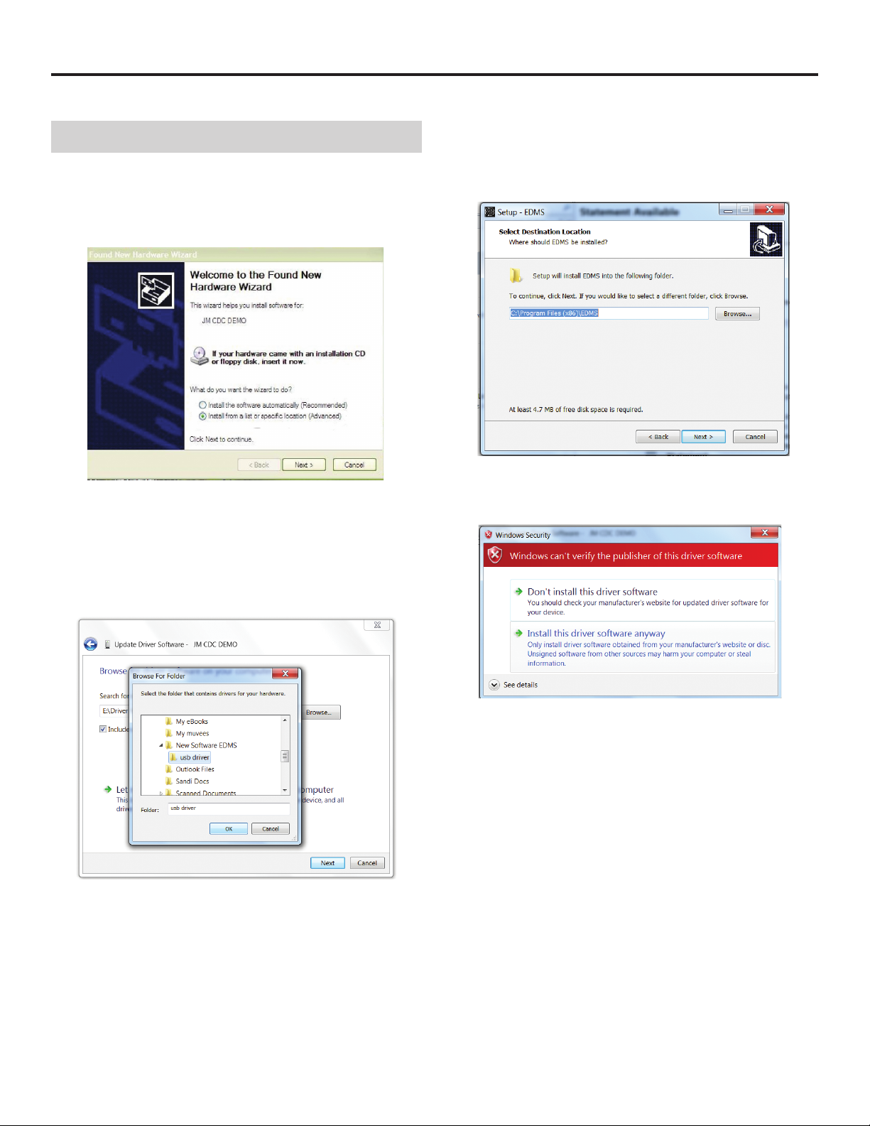
1. Install the USB Driver
1.1 If this is your first time using the gauge, when you connect the
gauge to the PC, a driver installation window may appear or the
driver will install automatically. Make sure gauge is on to initiate
process.
1.2 Select the USB driver path, that is in the EDMS software folder
location on your computer. If windows do not automatically appear, go to device manager and click on the JMCDC, then update
driver software. Browse computer for location, click next.
1.3 Click next
1.4 Select “Install this driver software anyway”.
1.5 Installation of the driver will take place.
1.6 If the driver was installed successfully, click “Finish”.
Page 2
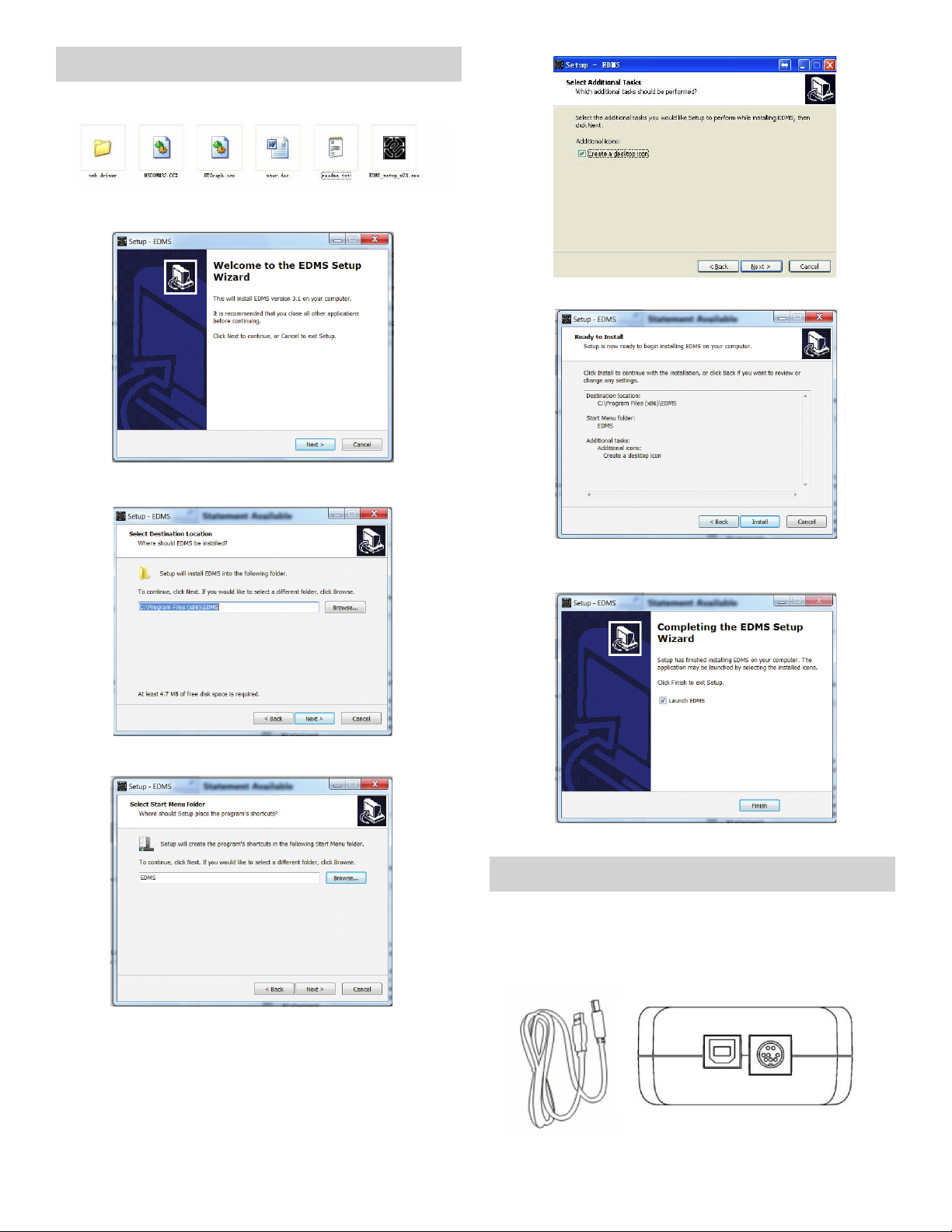
2. Install the EDMS Software
2.1 Double click the EDMS.exe
2.2 Click next
2.3 Set up the installation path and then click next
2.6 Install
2.4 Click next
2.7 Click finish to install
3. EDMS User’s Guide
3.1 Connect to PC
Connect the USB cable to force gauge, and then connect them
to PC. NOTE: The USB driver for this software should be installed
first.
2.5 Check box and click next to place an icon for the EDMS on
your desktop.
2
Page 3

3.2 Open the software
Turn on the gauge. Open EDMS by double clicking the software
icon. EDMS will identify the connection with gauge automatically.
If the connection is good, icon will display, otherwise this
icon will show on the button in the control area .
If is showing, it means the connection is not normal, you can
click button to try to connect manually. If you still can not connect, the following message will display: “Can not find the device
please reconnect the device or power on the device”. Check the
USB cable, the power of gauge, or possibly you need to install or
reinstall the USB driver.
3.4 Click the “Stop acquisition” button. The graph as well as the
data in the table will stop and be visible for review.
3.5 If you select the “Upload Memory Data From Gauge”, if any
data has been stored on the gauge’s memory, it will be uploaded
from the gauge to the program, after clicking the “Start Acquisition” button.
3.3 Click the “Start acquisition” button. The software will begin to
graph.
3.6 Functions
3.6.1 Export Data: Send data from test or uploaded from gauge in
CSV format to computer.
3.6.2 Export Image: Export or saves an image of the graph on
your computer in bmp format.
3
Page 4

3.6.4 Setting
Report Name: Create a name of the current data set or test.
Readings per Seconds: Sets the number of readings per sec-
ond that Software requests data from the gauge. The available
range is 0 to 60 readings per second.
Load: Change the load units.
Show Grid: Turns on or off the display of the grid in the
graph.
Invert Load: Inverts the load direction.
3.6.5 Advance
Set a zoom window with adjustable x- and y- dimensions for a
specific part of the graph.
Click this icon to
get the detail of
the graph. Then
click Calculate
to retrieve the
average and peak
data from the
highlighted area
of the graph.
Click the calculate
button to obtain
the avg and peak
data of the selected graph.
G: Set the gravity acceleration value
3.6.6 Test setup
Start Condition: Select the option for time delay (in seconds),
or load threshold that must be surpassed before test will commence.
Stop Condition: Select the option for time, or load that must
be surpassed to end the test.
Break Detect: Stop the test when the load decreases to a
specified percentage of the maximum (peak) reading during
the test.
3.7 Status bar
1 2 3 4
Through the status bar check the current software working condition
Click left button
on mouse, then
move the mouse
to highlight a
range on the
graph.
Zoomed in graph is
displayed. Click the
right button mouse,
to get the initial
graph, or click
and get the
initial graph.
1. Connected or Not Connect: If the gauge connects to the PC
when you open the software, it shows Connected or Not Connected.
2. Ready or Running: When “Ready” displays, the software is
not connected to gauge. When displaying “Running”, it means
the software is working.
3. The current version number.
4. The running time.
3.8 Error Massage
Check the connection to the gauge. Power of the gauge maybe
low.
When the software is connecting to the gauge, you should not
take the USB Port out, if it came out the message, you should
reconnect the USB port.
Element not found!
Copy the “Ntgraph.ocx” file to C:\WINDOWS\system32: cover the
old files.
4
Page 5

4. USB Driver Installation
Error Solution
4.1 If the USB driver was installed in error, you can manually install
the USB driver by the following steps:
Step1: Right button click my computer, select the Properties
Step 2: Click the Hardware
4.2 Solving a serial port conflict.
If you found your Blue tooth uses the same EFG com port, then
you cannot use the EDMS software. You must change the port
number, by the following steps:
Step 1:
Step 3: Check the port (COM &LPT)
If error exclamation symbol is on the JM CDC DEMO, it means
the USB driver was not installed successfully.
Step 4: Right button click and then select “Update Driver”. Then
you can install the driver (see Install the USB driver)
Step 2: Click Port Settings; Click Advanced
Step 3: Choose a port number to avoid the same port.
Then Click OK.
5
Page 6

Step 4: Click the Port (COM & LPT) Click the scan for hardware
changes.
The Serial port conflict should now be resolved. Connect your
gauge and start up the software to see if you can begin Acquisition as normal.
 Loading...