

Page 1

TRC Series
DIGITAL TORQUE CHECKER Series
Operation Manual
Read the manual thoroughly prior to operation.
Use the instrument only after reading the complete manual.
Follow all safety precautions.
Page 2
Warning
Safety Precautions
Be sure to read the entire instruction manual thoroughly before initial set-up, operation and maintenance.
The instruction manual provides three grades of safety precautions: “Danger”, “Warning” and “Caution”.
Follow these precautions.
Danger” marking indicates possible death, severe injury or fire
if the user disregarded.
Danger
Warning
Caution
“Warning” marking indicates possibility of a serious injury
if the user does not follow the instruction.
Caution” marking indicates possibility of severe bodily or object damage
if operated improperly.
__The following marks indicate the sort of contents which are completed with.__
his mark indicates warning.
his mark indicates a prohibited operation.
his mark indicates Execute this warning.
Heavy! Pay close attention to location and conditions around TRC.
Dropping the TRC may cause damage or serious injury.
Page 3
Caution
Never exceed torque ratings.
May damage sensor and other parts.
May cause damage or injury.
Do not carry TRC by AC power cable.
cause electric shock, fire and/or injury.
Confirm the specified AC voltage.
Other then specified voltage may cause damage,
electric shock, fire and/or injury
Do not substitute AC adapter.
Use only
the adapter supplied with the
unit.
Use of other then specified ac adapter may cause
damage, electric shock, fire and/or injury.
Insert AC connector into outlet
securely.
May cause electric shock, fire and/or injury
Do not alter, repair or dispose of
TRC or batteries improperly.
cause damage, accidents and void warranty.
Do not use with AC power in an
area
where there is dust.
An electrical spark may cause fire.
To clean, gently wipe with a soft
cloth.
No volatile chemicals such as usage of
Benzene,
Thinner, or Alcohol are to be used to clean
TRC
Check operation of TRC and
calibrate
periodically.
Place TRC in a location
where
maintenance and check are
easy.
Fix object securely.
May
May cause damage or injury.
Do not damage AC cable.
May cause electric shock, fire and/or injury.
Do not use except with 115VAC.
May cause electric shock, fire and/or injury.
Do not insert plug into AC
outlet
if hands are wet or moisture
is
present.
May cause electric shock, fire and/or
injury.
Do not pull out the AC plug
by the
cable. Carefully pull on plug
May
only.
Pulling on cable may cause electric
shock.
A
void the following.
Di
rect sunshine, condensation, dust or caustic
ch
emicals, combustible gases, oils, water, salts.
Operate within 32-104°°°°F (0-
40°
°C)
C)
°°
C)C)
Outside specified temperature range
may alter
operation of TRC.
Humidity range 35 –––– 85%RH
(Not condensation)
Operation outside humidity range may alter
operation of TRC.
Page 4

Contents
1 Feature ................................................................................................................................................................................1
2 Confirmation of Product Packing ........................................................................................................................................1
3 Names and Functions of Components ................................................................................................................................ 2
3.1 Mainframe..................................................................................................................................................................2
3.2 Operation Panel .........................................................................................................................................................3
3.3 Main Display............................................................................................................................................................... 4
3.3.1 Main Display/Setup Values................................................................................................................................4
3.3.2 Unit/Status Indicators........................................................................................................................................4
3.3.3 Battery Indicator................................................................................................................................................5
4 Parameters..........................................................................................................................................................................5
4.1 Function Setting .........................................................................................................................................................5
4.1.1 Function Mode ..................................................................................................................................................5
4.1.2 Operation...........................................................................................................................................................5
4.2 High/Low Limit Setting for Comparator .....................................................................................................................8
4.2.1 Pattern No. Setting ............................................................................................................................................8
4.2.2 Operation...........................................................................................................................................................9
5 Measurement Mode .........................................................................................................................................................10
5.1 Peak Mode ...............................................................................................................................................................10
5.2 Mean Mode..............................................................................................................................................................10
6 Comparator Function ........................................................................................................................................................11
7 Measuring .........................................................................................................................................................................12
7.1 Measurement of Torque Wrenches .........................................................................................................................12
7.2 Measurement of Electric Screwdrivers/Torque Drivers ...........................................................................................12
7.3 Zero Adjustment....................................................................................................................................................... 13
7.4 Measuring ................................................................................................................................................................ 13
7.5 Mounting Bracket.....................................................................................................................................................14
8 Memory Function..............................................................................................................................................................14
8.1 Saving Data in Memory ............................................................................................................................................ 14
8.2 Display Memory Data ............................................................................................................................................... 15
8.3 Clearing Stored Data (Latest Memory Data) ............................................................................................................ 16
8.4 Clearing Stored Data (Each Pattern No.) ..................................................................................................................16
8.5 Clearing Stored Data (All Memory Data).................................................................................................................. 16
9 DigiTorq_TRC.....................................................................................................................................................................17
9.1 Feature of DigiTorq_TRC ..........................................................................................................................................17
9.2 Download DigiTorq_TRC .......................................................................................................................................... 17
9.3 Battery Life and USB.................................................................................................................................................17
10 Support .............................................................................................................................................................................17
10.1 Repair and Calibration..............................................................................................................................................17
10.2 Warranty ..................................................................................................................................................................17
11 Specifications and Dimensions..........................................................................................................................................18
11.1 Specification .............................................................................................................................................................18
11.2 Dimensions............................................................................................................................................................... 19
Page 5
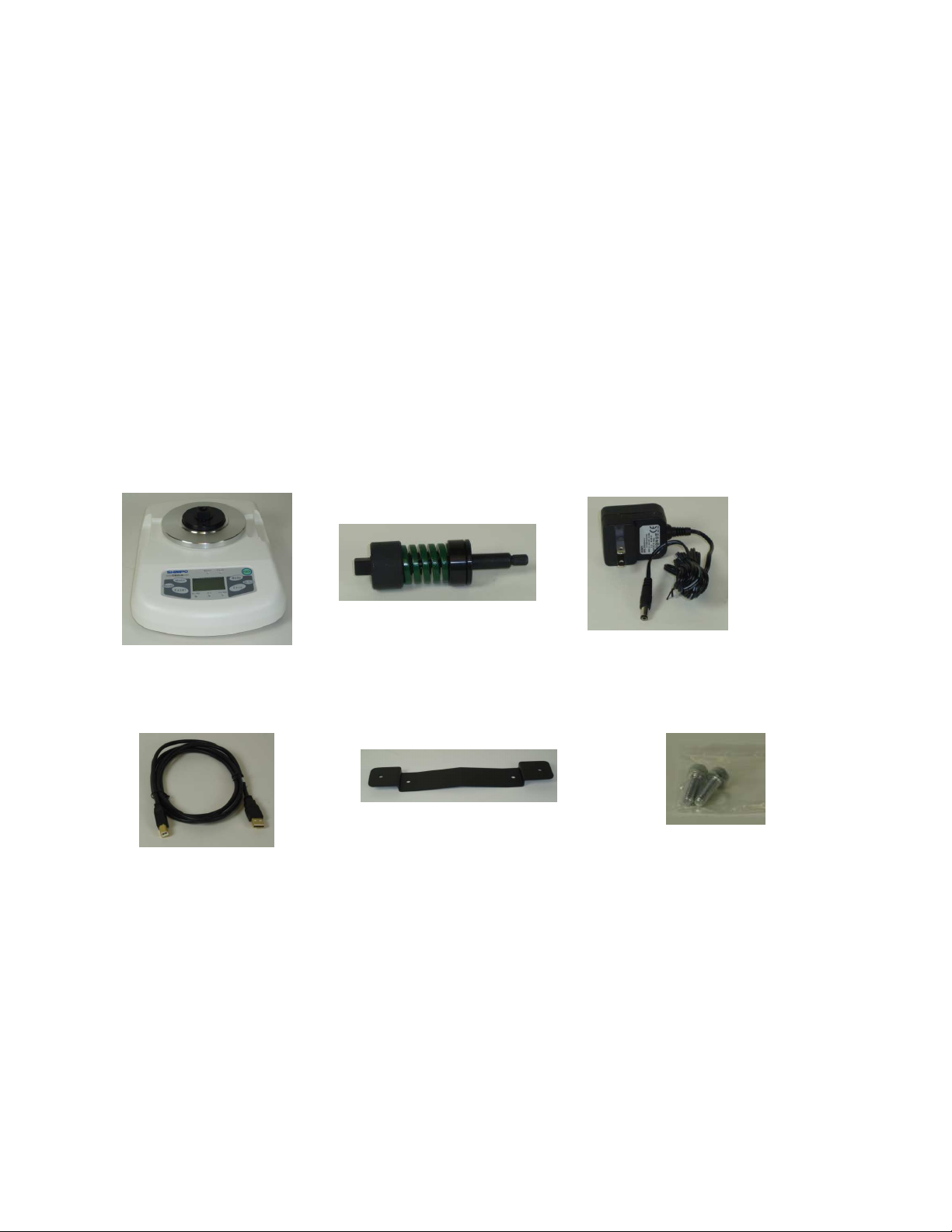
1 Feature
1. Mainframe (1)
3. AC adapter/charge
r (1)
4. USB cable (1)
2. Adapter for
torque
driver
6. Bolt M6x15 for
mounting bracket
(2)
7. Operation manual
8. Warranty card (1)
5. Mounting Bracket (1)
• Two measurement modes: Mean, Peak
• Peak hold & Auto reset of peak display
• Go/No Go judgment by comparator functions (LED indicator and Buzzer)
• Available 10 patterns of High/Low torque limits for judgment
• 300 data memories for each pattern (Total: 3,000 data)
• USB communication to PC (with “DigiTorq_TRC”operation software:)
• Selectable units: lb-in, N-m, N-cm, kg-cm
• Selectable Measurement periods: 1, 2, 4, or 8 times/sec
2 Confirmation of Product Packing
(1)
1
Page 6
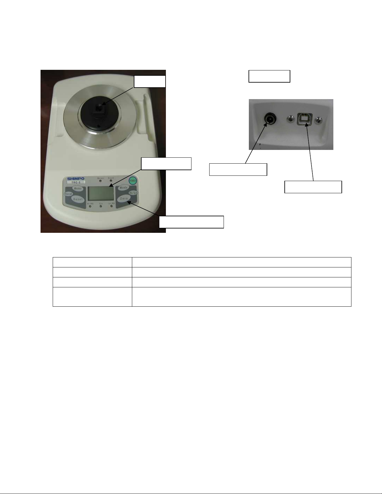
3 Names and Functions of Components
USB connector
LCD display
Socket
Operation Panel
Back side
DC power input
3.1 Mainframe
Socket Insert torque wrench or torque driver adapter
Operation Panel LCD display, Keys, LED indicators
USB Connector USB communication (B type)
DC Power Input
Insert AC adapter/charger when AC power supply is used or battery is being
charged.
2
Page 7
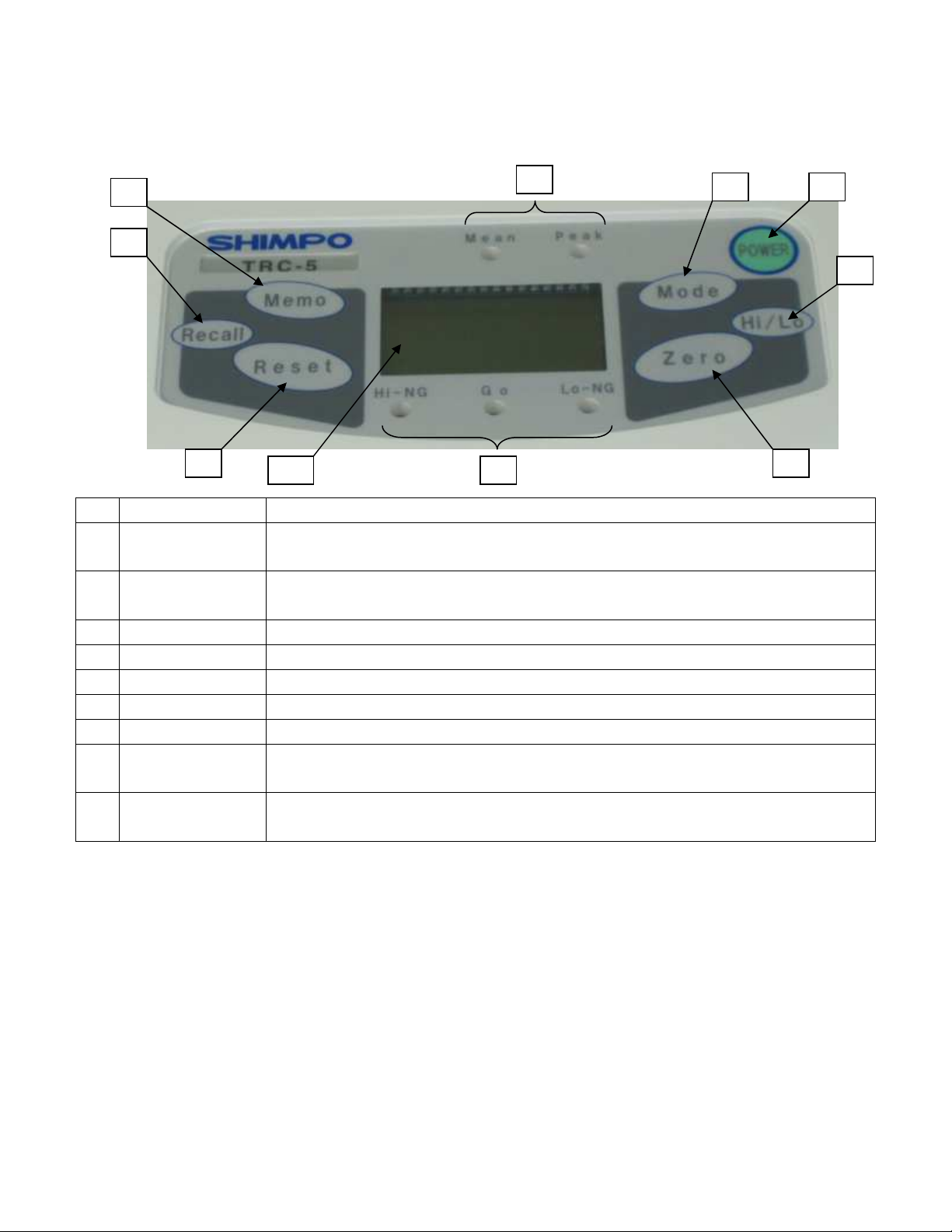
3.2 Operation Panel
2
3
4
5
6
7
8
9
10
1
1 POWER key Power the unit on or off.
2 Memo key
3 Recall key
4 Reset key Peak reset function in “Peak” mode.
5 Mode key Select “Mean” or “Peak” mode of operation
6 Hi/Lo key Sets the high/low limit values.
7 Zero key Sets Zero in “Mean” and “Peak” mode.
8 Mode LED’s Indicates which mode is selected: “Mean” or “Peak”.
9 Comparator LED’s
10 Main display
When in Peak mode, data is stored.
Note: In “Mean” mode, Memo key has no function.
Recall the peak data stored in “Peak” mode.
Note: In “Mean” mode, Recall key has no function.
When the high/low limit values are enabled, the LED indicates: Hi-NG or Go or Lo-NG
is ON. When the high/low limit values are disabled, all LED’s are off.
Displays measured values and status indicators. Includes units of measure, battery
status and function status.
3
Page 8

3.3 Main Display
3.3.1 Main Display/Setup Values
Main display shows four digits including decimal point.
The + sign means CW direction torque, the – sign means CCW direction torque in Mean mode.
IMPORTANT NOTE: In the case of Peak mode selection, the sign is always +.
3.3.2 Unit/Status Indicators
Located on the upper part of display, this shows the unit of measure selected.
It also serves as a sub display under function mode or status. The example display is shown in below.
lb-in unit N-m unit
lbI
Nm
Overload
OVR
1 minute warning
before it turns off
PWR
4
Page 9

3.3.3 Battery Indicator
Next page
Displayed according to battery status.
“LO BAT” blinking: “BAT”:
Battery diminished. Charging by AC adapter/charger.
Connect AC adapter/charger for charge.
LO
lbI
4 Parameters
4.1 Function Setting
4.1.1 Function Modes
Function modes are as follows.
Item Sub Display Setting Contents Initial setting
Auto reset F01 OFF/1/2/5 sec OFF
Unit of torque F02 lb-in/N-m/N-cm/kg-cm lb-in
Display update time F03 1/2/4/8 [times/sec] 4
Auto power off F04 OFF/10 [minutes] 10
Unit No. F05 0-99 0
BAT
lbI
4.1.2 Operation
With power off, press and hold Zero key then press POWER key.
Hold Zero key until the display shows “F01”.
Power
++++
Zero
5
Page 10

4.1.3
<Auto Reset
Selection
>
Save and exit
4.1.4
<Units of measure selection
>
Save and exit
Next page
The Auto Reset function automatically resets Peak after each setting period.
The Peak Reset function operates the same as pressing Reset key.
(Current setting is displayed first.)
Auto reset OFF
F01
Mode
F01
Mode
Mode
5 sec 2 sec
Hi/Lo
The torque units are selectable: lb-in, N-m, N-cm and kg-cm.
lb-in
lbI
Mode
1 sec
F01
F01
N-m
Nm
Mode
(Current setting is displayed
Memo
first.)
Ncm
Mode
Memo
Mode
kgc
Mode
Kg-cm N-cm
Hi/Lo
6
Page 11

4.1.5
<Display Update Time S
etting
>
Save and exit
4.1.6
<Auto Power Off Setting>
Save and exit
Next page
Display update time is selectable from 1/2/4 or 8 times/sec.
1 time/sec
F03
Mode
F03
Mode
Mode
8 times/sec 4 times/sec
Hi/Lo
If the TRC is on battery power and there is no activity for 10 minutes, the TRC automatically
powers off to conserve battery power. This option may be disabled. Auto Off is disabled when
connected to AC adapter/charger.
Auto Off time defaults to 10 minutes
. No other time is available.
(Current setting is displayed first.)
2 times/sec
F03
Mode
Memo
F03
(Current setting is displayed first.)
Disable
F04
Mode
Enable 10 minutes
F04
Memo
Mode
Hi/Lo
7
Page 12

4.1.7
<Unit No. Setting>
Current unit No.
LSD(Last Significant Digit) blinking
Save and exit
F05
Go to Auto Reset Setting
The ID No. can be individually applied.
Mode
MSD(Most Significant Digit)blinking
F05
Recall
F03
Press Mode to increment, return to 0 when 9
Press Recall to go to MSD setting
Recall
Press Mode to increment, return to 0 when 9
Mode
F05
Hi/Lo
4.2 Comparator settings for High/Low Limits
(Current setting is displayed first.)
Memo
4.2.1 Pattern No. Setting
The TRC can store up to 10 patterns of High/Low torque limits.
This section describes how to set the pattern No.
The pattern No. is from 0 to 9.
When a torque unit of measure is displayed, the Comparator function may be disabled.
Disabled comparator
lbI
Hi/Lo
-0-
Hi/Lo
Hi/Lo
Pattern No.
-1-
-9-
Hi/Lo
Hi/Lo
-2-
8
Page 13

4.2.2 Operation
To s
ave
Hi/LO limit
setting
s,
go to
M
easurement mode
.
(Section 5)
<High Limit Setting> Hi
-
NG LED on
Measurement Mode
Move
1 digit to the
right
Press Reset, move to digit
on right
.
<Low Limit Setting> Lo
-
NG LED on
Start setting
MSD: Most Significant Digit
Select the pattern number according to above Section 4.2.1. Pattern No. Setting.
Low limit data
Reset
Move 1 digit to right
-1-
Hi/Lo
1-L
Press and hold Hi/Lo until the display shows “1-L”.
Reset
1-L
Return to MSD when LSD is displayed.
MSD blinking & setting
1-L
Press Memo to increment.
Returns to “0” after 9 is
displayed.
LSD: Least Significant Digit
(Current setting is displayed first.)
Memo
1-L
1-L
Reset
Mode
(Current setting is displayed first.)
High limit data
1-H
Mode
Note: Low limit value must be smaller than High limit value. If the setting data is
incorrect, all digits will be blinking. Turn TRC off and reset limits.
Key operation is the same as Low limit setting above.
9
Page 14

5 Measurement Modes
Mean Peak
Mean Peak
Mean Peak
Mean Peak
Peak, Mean Measurement modes are available on the TRC:
To select the measuring mode required for testing, follow the settings below.
Mean Mode
Peak Mode
5.1 Peak Mode
The Peak value displayed on the TRC is measured at 1,000 times per second. (1000Hz)
The Peak value is reset by pressing the Reset key or activating the Auto reset function (refer to 4.1.3
Auto Reset Setting).
Set zero by pressing Zero key.
5.2 Mean Mode
The mean mode is the real time value based on the average data captured in 1,000 samples per second.
(1000Hz)
F03 Display Update time Average
1 1 time/sec Displays the average of 1,000 measuring data by 1msec sampling
2 2 times/sec Displays the average of 500 measuring data by 1msec sampling
4 4 times/sec Displays the average of 250 measuring data by 1msec sampling
8 8 times/sec Displays the average of 125 measuring data by 1msec sampling
lbI
lbI
lbI
Mode
Mode
lbI
Zero
Press and hold Zero key
until the display shows
“0”
10
Page 15

6 Comparator Function
• This function compares the High/Low limits and measured data (Mean Mode) or peak data (Peak
Mode) or memory data. The result is displayed by Comparator LED indicators.
• If both High and Low limits are set to 0, the Comparator function is deactivated. Refer to 4.2.2
Operation.
• The buzzer sounds and the “Go” LED illuminates when the displayed data is between the High and
Low limits.
- In Peak mode, the buzzer sounds when the peak value is fixed.
- In Mean mode, the buzzer sounds every 1 sec.
Note: When the displayed value is less than 1% of the torque rating, the buzzer does not activate.
• Comparison is used with all completed data.
<Example of comparator function>
High limit = 100, Low limit = 50
Measurement of CW direction
+
100 High limit
50
0
Hi-NG: ON
Go: ON
Low limit
L0-NG: ON
-
Measurement of CCW direction
+
0
Lo-NG: ON
50
Go: ON
100 High limit
Hi-NG: ON
Low limit
-
11
Page 16

7 Measuring
Socket
for torque
wrench
Attachment for driver
Adapter for driver
7.1 Torque Wrench – torque measurement
To measure torque, insert the torque wrench square drive into the TRC socket attachment.
7.2 Electric Screwdrivers/Torque Driver - torque measurement
To measure torque, insert the adapter into the attachment of the TRC as
shown below.
Torque wrench
Driver
The torque driver adapter is designed to measure in only the CW (tightening) direction.
Note:
12
Page 17

The adapter is a consumable product.
Loosen (CCW direction)
Tighten (CW direction)
Replace the adapter when it is impossible to perform a repeatable measurement.
7.3 Zero Adjustment
In “Mean” mode, press the Zero key when the display does not display “0” and no torque is applied.
In “Peak" mode, press the Zero key when the display does not display “0” if the automatic peak reset
function is not activated.
7.4 Measuring
The measured torque data is displayed with a given torque test.
When the TRC is in “Peak” mode, press Reset key to reset the Peak function before the next torque test.
NOTE: Peak reset cannot operate while torque is applied.
Spring shrinks
Spring returns
13
Page 18

7.5 Set Mounting Bracket
M6 tap (2)
Hole x2 (Ø7mm)
Bolts M6x15 (2)
for
mounting
10.63” (270mm)
Return to measuring mode after 1 sec
Secure the TRC to a work bench or other suitable surface by using the mounting bracket accessory if the
TRC moves during measurements.
Procedure to mount the mounting bracket:
1. Prepare the mounting bracket (1) and bolts M6x15 (2) of accessories.
2. Set the mounting bracket to the bottom of the unit by the bolts as shown below.
3. Set the unit to worktable using two holes (diameter 7mm).
Bottom of TRC
8 Memory Function
8.1 Saving Data in Memory
Measuring torque data can be stored in the unit by pressing Memo key.
The feature is only available in Peak mode.
The unit is able to store 300 data for each pattern of High/Low limits.
Pattern No. 1
-1-
Memo
Mounting
Saving data
“003” is the 3rd data.
003
Peak reset
after 1sec
-1-
If the stored data of this pattern is already 300,
the display is “FULL” and the data can not store.
-1-
14
Page 19

8.2 Display Memory Data
Minimum
Maximum
Return to test mode
Memory number
Latest memory data ind
icates
Memory number
Return to
Select Peak mode, press the Recall key and the TRC display will indicate the number of data stored in the
memory.
The Memory data is displayed from the last number stored.
Measuring mode
Pattern No.1
-1-
Recall
300
Recall
Average
Recall
AVE
MAX
last memory
data stored
stored
001
Recall
Operation same as
Memory data 300
Recall
Memory number
decrement
299
Recall
Recall
MIN
Recall
300
Mode
-1-
15
Page 20

8.3 Clearing Stored Data (Latest Memory Data)
Indicating target
+
C
lear display
Indicating about 1 sec
Return to test mode
+
Power off
Clear display
Indicating about 1 sec
Return to test mode
When the latest memory data is displayed, press and hold the Zero key until “Clr” is shown in the display.
Latest memory data indicates
Press and hold until clear display
Clear display
Zero
300
New latest memory data
299
Indicating about 1 sec
In case of latest memory number = 001:
Memory No. =001
001
Zero
Clear display
Indicating about 1 sec
8.4 Clearing Stored Data (Each Pattern No.)
When the pattern No. is displayed, press and hold the Memo key and the Zero key until “Clr” is shown in
display.
pattern No.
-1-
Memo
Zero
-1-
8.5 Clearing Stored Data (All Memory Data)
Power off. Press and hold the Memo key and power on. Continue to hold the Memo key until “All Clr” is
shown in the display.
Memo
Indicating No data
Return to
Test mode
Indicating about 1 sec
-1-
POWER
16
ALL
-1-
Page 21

9 DigiTorq_TRC
When you connect the TRC to a PC with the USB cable, your PC is able to obtain test data from the TRC.
Installation of the DigiTorq_TRC application software is required.
9.1 Feature of DigiTorq_TRC
DigiTorq_TRC is an add-in software for MS Excel ®*
The measurement data and the memory data of the unit can be directly sent to an
Excel spreadsheet where graphing and data analysis is easy.
*Excel is a registered trademark of Microsoft Corp.
9.2 Download DigiTorq_TRC
The DigiTorq_TRC is available for free at the following web address:
http://www/shimpoinst.com/software.php
The manual is included with the software download, and is available separately.
9.3 Battery Life and USB
Leaving the USB cable connected to the TRC will drain battery power at a faster rate. Only connect the
TRC USB cable when communicating or use the AC adapter/charger.
10 Support
10.1 Repair and Calibration
Please contact your Shimpo dealer for information regarding the repair and calibration of your TRC.
10.2 Warranty
Nidec-Shimpo Corp. warrants, to the original purchaser of new products only, that this product shall be
free from defects on workmanship and materials under normal use and proper maintenance for one
year from the date of original purchase. See warranty card.
17
Page 22

11 Specifications and Dimensions
11.1 Specification
TRC Series Digital Torque Checker
TRC Models TRC-2 TRC-5 TRC-10
Measuring Units N-m, N-cm, lb-in, kg-cm
0.020-2.000 N-m 0.050-5.000 N-m 0.10-10.00 N-m
Measuring Range
Main Display 4-digit LCD display, Character height 12mm
Display
Buzzer Available (Result of comparator, completing to measure, etc.)
Accuracy +/- 0.5% Full Scale
Measuring
Display Update Time
Sampling Rate 100 times/sec (10msec)
Memory
Data Output USB1.1
PC Software
Standard Accessories
Power
Dimensions DxHxW inch(mm) 12.60”x3.82”x8.66” (320x97x220mm)
Shipping Weight 18lb (8kg)
Operation Environment
Battery Type/ Battery Life Ni-MH / 8 hours after full charge
Battery Recharger Time Maximum 16 hours
Sub Display 3-digit LCD display, Character height 7mm
Mode Display Mean, Peak (red LED indicators)
Comparator Display Hi-NG, Go, Lo-NG (green and red indicator)
Mean Mode Measuring real time torque
Peak Mode Measuring peak torque
Memory data number Total 3,000 data (300 data/ each pattern [Total 10 patterns])
Statistical Process Average value, Maximum value, Minimum value
Battery Built in nickel metal hydride battery (NiMHd)
AC adapter/charger 100-240VAC input/ 9VDC 300mA
2.0-200.0 N-cm 5.0-500.0 N-cm 10-1000 N-cm
0.18-17.7 lb-in 0.45-44.25 lb-in 0.89-88.50 lb-in
0.21-20.39 kg-cm 0.51- 50.99 kg-cm 0.1-102.0 kg-cm
Select from 0.125sec (8 times/sec), 0.25sec (4 times/sec),
0.5sec (2 times/sec), 1 sec (1 time/sec).
DigiTorq_TRC(free download from web site: www.shimpoinst.com)
Torque adapter for driver, AC adapter/charger, USB cable, Mounting
bracket, bolts for mounting bracket (2 pcs)
32-104° F (0 – 40° C)/ 35-85% RH (non condensation)
18
Page 23

11.2 Dimensions
When Spring
4.37” (111mm)
0.25”(6.35mm) Hexagon
12.20” (310mm)
8.66” (220mm)
0.35” (9.5mm)
10.63” (270mm)
Operation Panel
Socket
2-Ø0.28”
(2-Ø7mm)
1.97”
(50mm)
Mounting Bracket (Accessory)
Mounting bracket
□
Wrench
Attachment
Driver
Attachment
Max. Length
12.60” (320mm)
Ø1.18” (30mm)
Adapter for Driver
19
 Loading...