

Page 1
Page 2

Contents
I. Introduction ............................................................................................................................................ 2
II. What is the TNP Torque Meter? ....................................................................................................... 3
III. Product Features................................................................................................................................. 3
IV. Parts and Functions........................................................................................................................... 4
V. Main Display (Description) ................................................................................................................ 5
VI. Secondary Functions ........................................................................................................................ 6
VII. Function Mode Table........................................................................................................................ 7
VIII. Operation.......................................................................................................................................... 11
XI. Zero adjustment / Tare the TNP .................................................................................................... 14
XV. Sample Applications ....................................................................................................................... 19
XVI.Specifications and Drawing .......................................................................................................... 20
XVII.Other Shimpo Products................................................................................................................. 21
1
Page 3
I. Introduction
Thank you for choosing the TNP Digital Torque Tester. With proper use and
operation, this unit will provide many years of reliable service.
Upon receiving the unit, please check for any obvious physical damage that may
result from shipping. If any damages found, please notify your carrier
immediately before shipping back to Nidec-Shimpo America for inspections and
possible repairs.
Contact Information:
NIDEC SHIMPO AMERICA CORPORATION
INSTRUMENTS DIVISION
1701 GLENLAKE AVENUE
ITASCA, IL 60143
(800) 237-7079
Each package includes the following:
• Operations Manual
• Software Installation Disk (Digitorq Software)
• Warranty Card
• USB A to USB B communication cable
• Universal AC adapter (100-240 VAC)
• Set of 30 mm chuck pins (4 pieces)
• TNP unit
Prior to operation read this manual carefully to understand and maximize the use
of this Digital Torque Tester. Have this manual handy for future reference and
information.
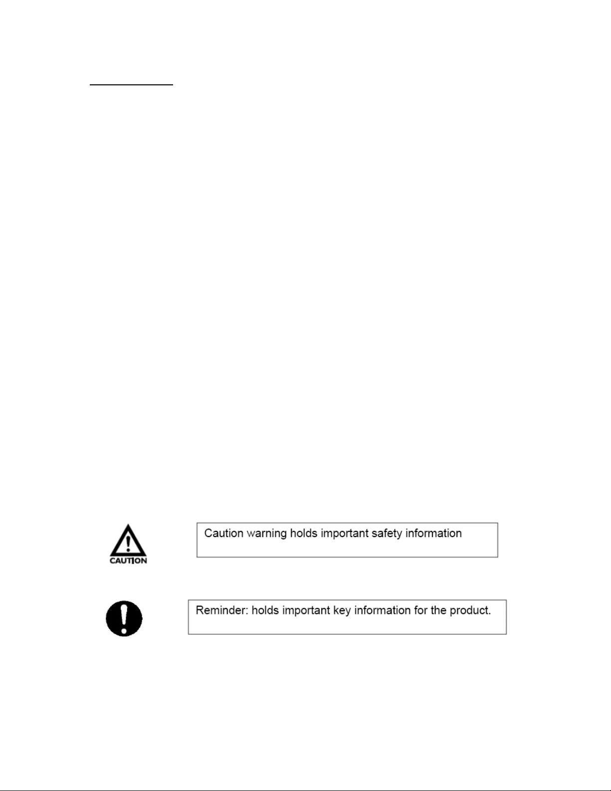
Observe the following important indicators.
2
Page 4

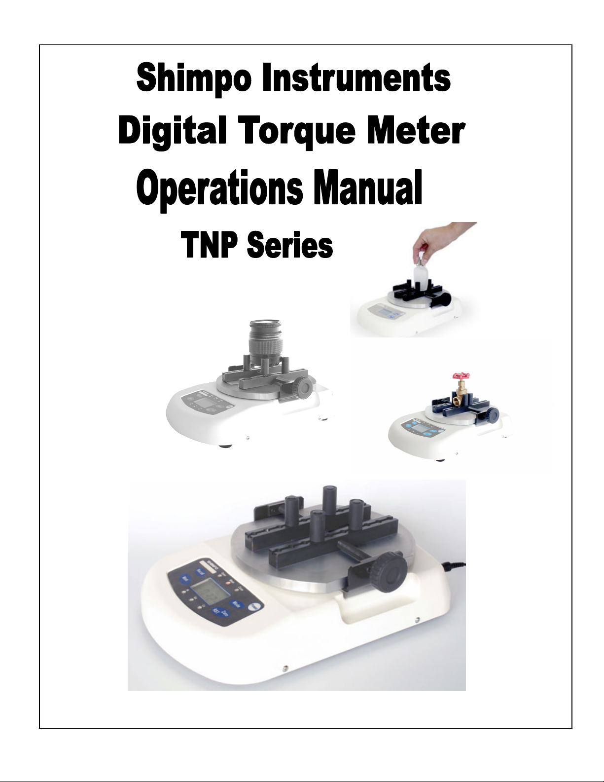
II. What is the TNP Torque Meter?
The TNP torque meter is a portable static torque measuring device that can be
used as a quality assurance tool for various applications that require
measurement of turning (both opening and closing) and twisting.
Some of the industries that can utilize this
equipment are:
• Pharmaceutical
• Food/ Beverage
• Cosmetic products
• Packaging
Equipped with internal rechargeable batteries, the
TNP can operate as a portable DC powered
device or thru the universal AC adapter.
Designed with a small footprint it can easily be transferred to maximize use
around the shop floor or the laboratory.
The programmable HI-LO set points make this unit ideal for pass-fail testing in a
production environment.
Do not test products that are filled with liquid as the TNP
torque tester is not protected from liquid spills.
III. Product Features
• High Accuracy: ± 0.5% F.S.
• Wide Torque Range: 0.5Nm, 2Nm, 5Nm and 10Nm (available models)
• Adjustable Sample Size: 10-190 mm diameter (0.39”-7.48”)
• Selectable units for measurement:
TNP-0.5 : mN-m, N-cm, g-cm, lb-in
TNP-2, 5, 10 : N-m, N-cm, kg-cm, lb-in
• Large Display: Easy to read digital display
• PC Output: USB interface with add in software (Digitorq)
• Flexible Power: Can run with built in rechargeable NiMH batteries or
Universal AC adapter
• Selectable Measuring Modes: Captures Peak Opening, Closing and
Average (CCW, CW)
• Portable: Small foot print, compact design, space saver
• Programmable HI and LO set points for Pass-Fail testing
• Store up to 1000 values into memory
• Selectable Display update time ( 8 times/second maximum)
3
Page 5
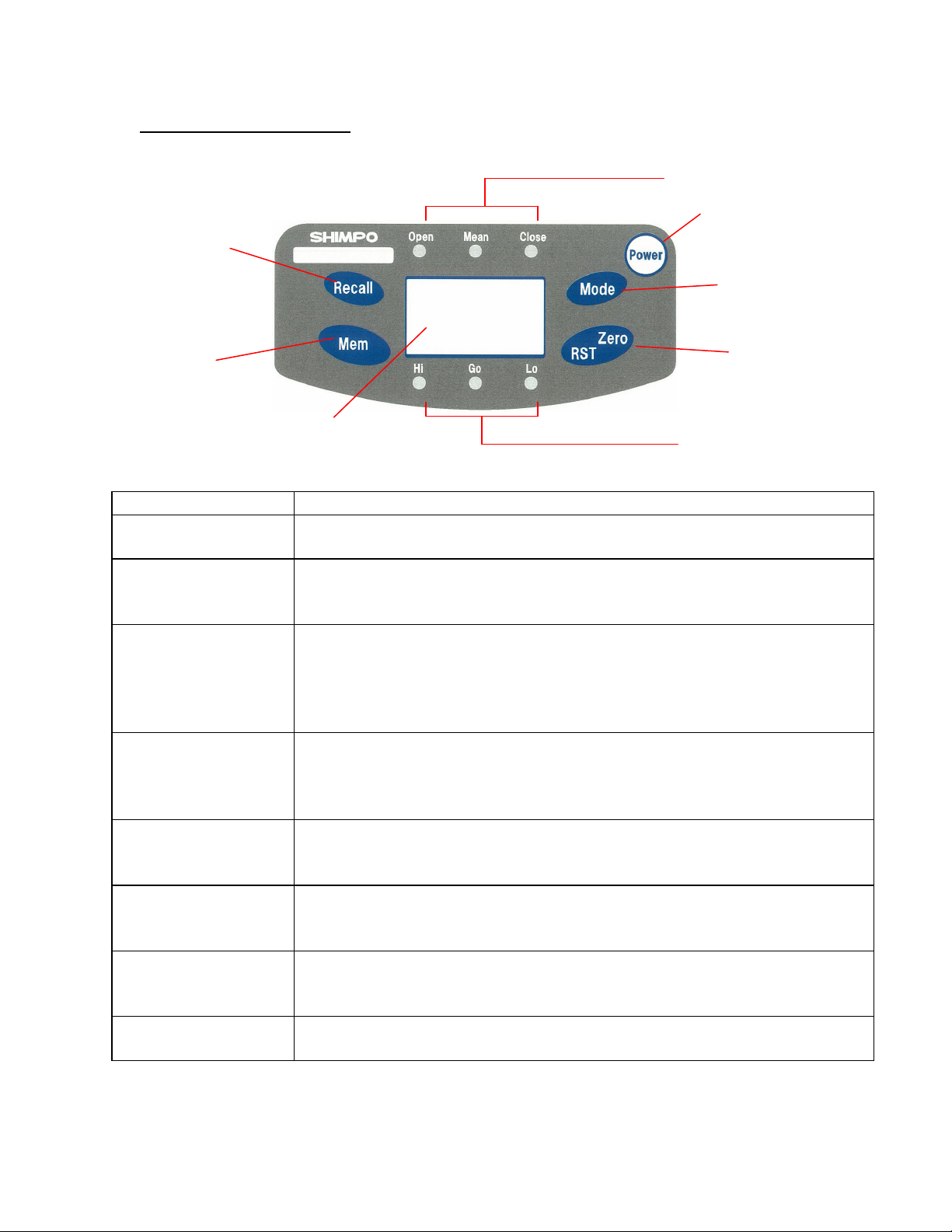
IV. Parts and Functions
Recall Key
Main Display
Parts Functions/Description
Power key
Turns the unit ON and OFF.
Recall data stored in OPEN and CLOSE modes.
Recall key
NOTE: in Average or Mean Mode, the Recall button has no function
Memory key for storing data in Open and Close Modes.
Note: In Mean mode the Mem key has no function. In this mode
Mem key
data cannot be stored in memory.
Mem combined with another key is used in secondary functions.
(Parameter and clear settings – see next section).
Selects mode of operation (CLOSE, MEAN, and OPEN)
Mode key
Serves as an exit function when in Memory recall.
Secondary function in parameter settings (see next section)
Tare or zero function for resetting and initializing values while in
Zero/RST key
Average or peak mode.
Secondary function in parameter settings (see next section)
Displays measured values and status indicators, which includes
Main Display
units of measure, battery status and function status.
Measuring mode
indicators
Comparator LED
Indicators
Red LED mode indicators. Informs which mode is selected “Open”,
“Mean” or “Close”.
Quick pass/fail visual indicators for all modes of measurement.
The LED indicator does not light when comparator feature is OFF.
Measuring mode indicators
Power key
Mode Key
Zero/RST Key Memory Key
Comparator LED indicators
4
Page 6
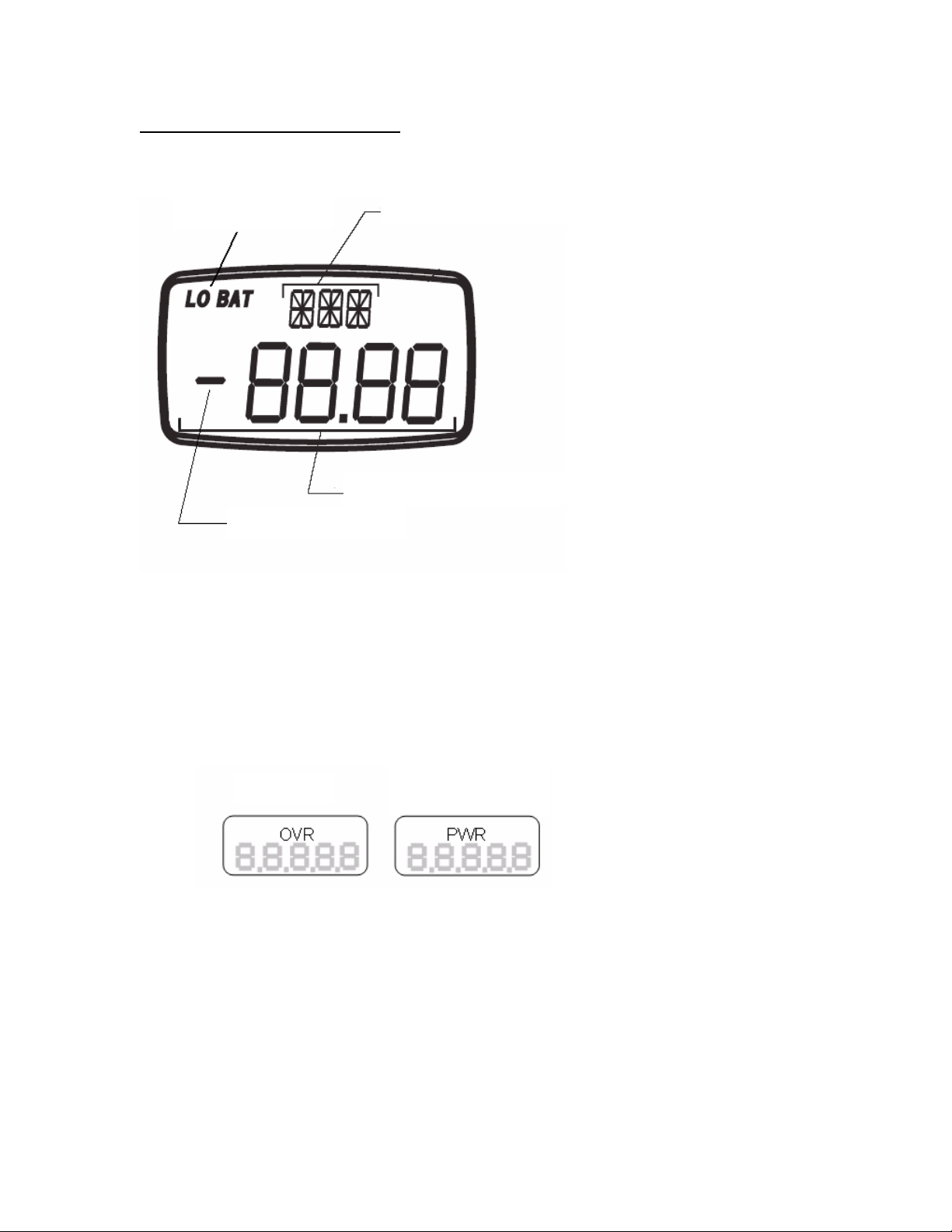
V. Main Display (Description)
1 minute warning
Battery Indicator
Direction Indicator
Units/Status Indicator
Main Display/ Setup Value
Extended Description
• Units/Status indicator – located on the upper part of the display this
shows the current units of measure selected for the torque meter. It also
serves as a sub display under function mode (F01, F02, F03, etc.)
Example: “OVR” indicates an overload condition the TNP went over its
rated capacity. “PWR”, the auto power off feature is set this indicator
serves as a 1 minute warning before the unit turns off.
Overload
before it turns off.
• Main display/Set up Values – shows the measured value in four digits
including decimal places. While under function mode, this displays the
options for each setting.
• Direction Indicator – indicates direction of applied torque based from F04
setting (Please see sign orientation information from function mode table).
By default, closing indicates a negative “-“values; Opening “no sign”.
5
Page 7
• Battery Indicator – shows the status of the TNP internal battery. “LO
BAT” appears on the display to indicate a low battery status. “BAT” is
shown when the TNP is charging. This indicator disappears when the
battery is fully charged or when the AC adapter is disconnected from the
TNP. It is important that the battery be cycled properly to achieve the
maximum life from it.
VI. Secondary Functions
Parameter window settings: by using certain key combinations the parameter window can
be accessed.
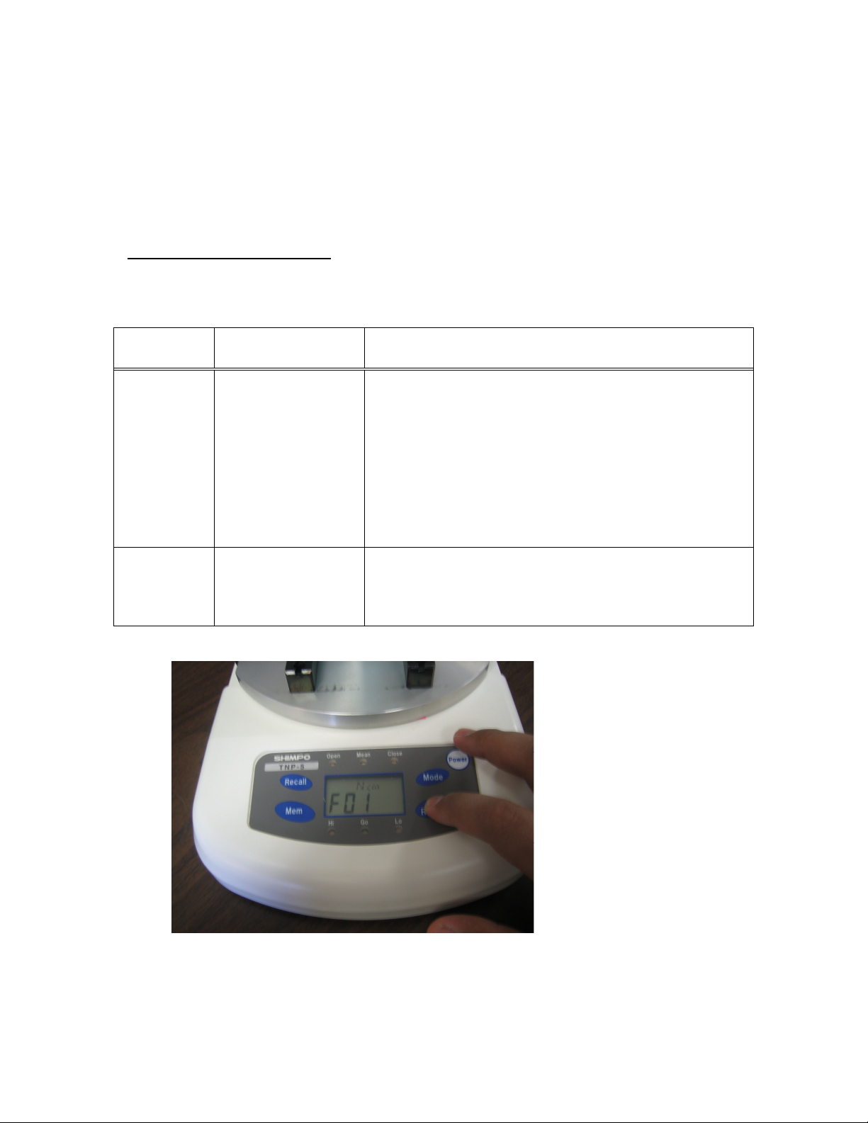
Operation
key
Operation How to operate
With Power off, press and hold the Zero/RST key
then power ON the torque meter. Continue
holding the ZERO/RST key until the display
Zero/RST
Power
Function mode
shows “F01”, Pressing MODE changes the value
of the selected function mode. Pressing the
“Zero/RST key” advances from one parameter
to the next. The lists of function are provided in
the next section. (See picture below for additional
description).
With Power off, press and hold the Mem key,
Mem
Power
Clear memory
data
then power ON the torque meter. Continue
holding the Mem key until “nonE” appears on
the display.
This picture indicates the torque meter is in Function Mode.
6
Page 8

If the display shows the normal operation of the torque meter, and no
F01 is seen on the display, the Zero/RST key was released earlier than
what is required. Turn off the torque meter and repeat the process.
VII. Function Mode Table
FUNCTION Sub display
Measuring unit F01
Options Initial setting
Changes units of measure
TNP-0.5 :
mN-m, N-cm, g-cm, lb-in
TNP-2, 5, 10 :
N-m, N-cm, Kg-cm, lb-in
TNP-0.5 : mN-m
TNP-2, 5, 10 : N-m
Display-(update rate) F02 Switch 1, 2, 4, 8 times/second
2
Auto power OFF F03 10 minutes or on 10 minutes
Sign Orientation F04
Upper comparator
value (Hi limit)
Lower comparator
value (Lo limit)
HI
LO
-0000 CCW (Open "-");
0000 CCW(Open "+")
0000 – 9999: with decimal
point. (Setting the values to
zero disables this function) .
0000 – 9999: with decimal
point (Setting the values to
zero disables this function).
0000
0000
0000
How to change value on the function selected?
To change the values of the function selected, use the Mode key button to scroll
through the options and the Zero/RST button to move to the next Mode.
Pressing the Mode button after setting the HI/LO limits exits out
of the function mode. You will need to reenter the settings to
change additional values.
7
Page 9

Operation diagram of how to access the Function Mode
Press and hold the Zero/RST key
Ncm
Kg
c
lb
i
Ncm
gcm
lbi
Turn OFF the TNP before starting
Power
Zero/RST
Power on then release the Power button
but continue to hold Zero/RST key until display F01
Function Mode – Measurement unit
TNP-2, 5, 10
Unit: N-m
Nm
Mode
Unit: N-cm
Mode
Unit: lb-in
Mode
Unit: Kg-cm
TNP-0.5
Unit: mN-m
mNm
Unit: N-cm
Mode
Mode
Unit: lb-in
Mode
Unit: g-cm
Zero/RST
Pressing Zero/RST, it moves to the next function setting.
Use the MODE key to change values of each function.
Use the Zero/RST key for moving to the next function
Mode
Mode
8
Page 10

02
f04
f04
Function Mode – Display (update rate)
1time/sec 2times/sec
f02
Zero/RST
Function Mode – Auto power OFF
Disable auto power OFF
f03
Zero/RST
Function Mode – Sign Orientation
Open “+”
Mode
f02
Mode
8times/sec
4times/sec
f02
Mode
f02
Mode
Pressing Zero/RST, it moves to the next function setting.
Set auto power OFF to
10 minutes
Mode
Mode
Pressing Zero/RST, it moves to the next function setting.
Mode
Mode
f03
Open “-“
Zero/RST
Pressing Zero/RST, it moves to the next function setting.
Use the MODE key to change values of each function.
Use the Zero/RST key for moving to the next function
9
Page 11

Function Mode – Upper comparator value (Hi Limit)
Present upper value
HI
Recall
HI
Move to the right
Move to right side one by one by pressing
Mem key.
Function Mode – Lower comparator value (Lo Limit)
Zero/RST
Pressing Zero/RST, it moves to the next function setting.
Present lower value
LO
Key operation is the same in entering the Hi limit value.
Zero/RST
Move to setting register/ standard display
Use the MODE key to change values of each function.
Use the Zero/RST key for moving to the next function
Recall
HI
Recall
Plus 1 by pressing
Recall key
HI
Press Mem key scrolls back to
the 1st digit position,
HI
Mem Mem
Move to the right
10
Page 12

VIII. Operation
Pretest Checklist:
Determine the size of the sample to be tested. Adjust the 4 jig on the testing
table accordingly. Center the sample and use the knob to secure the sample in
place (clockwise to tighten the jig to the sample material).
It is important to make sure that all the jigs are flush to the moving brackets.
Each one of these jigs has set pins which slides into place inside the grooved
brackets.
Measuring Modes
Measuring Modes available on the TNP: OPEN, CLOSE, MEAN
Select the measuring mode required for testing. Please check the settings below
on how to select the right mode for testing.
Open mode
Open
Mean Close
Nm Nm Nm
Mode
Mean mode
Open
Mean Close
Mode
Mode
Close mode
Open
Mean Close
Pressing the Mode key toggles through the mode available from the TNP, LED
indicators are provided to display current selected mode.
OPEN and CLOSE modes are PEAK Values captured by the TNP, these values
are not real time values, and are retained on the display until one of the following
occurs, the Zero/RST key is pressed or a higher peak value is detected (which in
this case, replaces the current value detected).
11
Page 13

Nm
Resetting the Peak values to Zero
Open
Mean Close
Nm
Zero/RST
Open
Mean Close
MEAN is real time value based on the average data captured in 1000 samples
per second.
The maximum display update for all modes is 8 times/second.
This update rate can be adjusted by changing F02 from function mode
(See section VII - Values available 1, 2, 4, 8 times/second).
Comparator Function
This compares the measured value to the upper and lower limits entered under
function mode for HI and LO limits.
If both HI and LO limits are set to “0000” this feature is not available
(deactivated).
The following conditions are valid under comparator mode:
• HI>LO
• HI=LO (HI Red LED indicator will be lit on the Comparator LED indicators).
Utilizing this feature makes it an ideal tool for quality assurance checks.
Example: HI is set to 100 and LO is set to 50. Based from the conditions met
the corresponding LED will light up (HI (Red LED), GO (Green LED), LO (Red
LED)).
Test 1 = 105 HI
Red LED
Test 2 = 45 LO
Red LED
Test 3 =65, GO
Green LED
100 Upper limit value
50
0
HI:ON
OK:ON
Lower limit value
LO:ON
From the previous example any values greater than 100 will light up the HI red
LED.
Any values lower than 50 will light up the LO red LED.
Values measured in between these values (100<X<50) will give a GO green LED
indicator.
12
Page 14

How to change the HI and LO values from the TNP torque meter?
• To set the HI and LO limits from the TNP torque meter access the function
mode. (See section VII).
• Power off the torque meter
• Press and hold the Zero/RST key then power on the torque meter.
• Continue to hold on the Zero/RST key until the main display shows F01
• Press the Zero/RST key until the main display shows HI limit
• Using the Recall key we can increment the highlighted digit from 0-9.
• Press the Mem key to move from left to right or to the next digit.
• Entering values that are invalid the display will blink momentarily indicating
wrong values entered to the HI and LO limits. (HI>LO, HI=LO).
After entering the LO limit value and pressing the Zero/RST button the
torque tester will go back to normal operation.
13
Page 15

XI. Zero adjustment / Tare the TNP
Taring or zeroing the value of the TNP initialize the torque meter to zero.
This function is performed by pressing Zero/RST button on the front panel. In
OPEN and CLOSE modes this zeros out the Peak values measured.
It is essential that the TNP be zeroed out before performing another
test. This ensures that the TNP is properly initialized and no
additional values are added to the measurement.
XII. Saving Data in Memory
Data can be stored in the TNP meter by pressing the Mem key. This feature is
only available in OPEN and CLOSE measuring modes.
NOTE: In MEAN or Average mode the Mem key has no function.
“Open”or“Close”
measuring mode
Nm
Memory registration
Mem
001
After 1sec, the peak value displayed will
automatically reset to zero; ready for
another test.
Nm
When the number of data points > 1000
Nm
After 1 sec, digits will return to original display.
Memory identification/Number
001
Taking a closer look at display the upper sub-display indicates the
memory identification or data number.
14
Page 16

XIII. How to recall stored Memory
Select Open or Close Mode, press the Recall key and the display will indicate the
number of data stored in memory.
Press Recall key second time to access the following information.
• AVERAGE Value
• MAX Value
• MIN Value
• Stored data (Data order of recall is based from the last data stored in
memory)
Displays Max Values after pressing Recall
To access the stored measured value use the Recall key to scroll thru the values.
(This will be after the MIN value is displayed). The display will flash two sets of
numbers, the first number indicates the memory ID and the second number is the
value stored on that memory ID.
NOTE: The order of values is from the last data stored to the first data stored. To
review previous values shown, scroll through the values using the Recall key.
15
Page 17

Nm
Nm
(1sec interval)
Nm Nm
(1sec interval)
Picture above indicates the memory ID followed by the stored data. Pressing the
mode button anytime exits out of the memory window. Below is a flowchart of
how the recall function works.
Recall
Power key
Recall
Average value
AVE
Recall
Maximum value
MAX
Recall
Last memory number, data display
Available Zero/RST key on main
display
Minimum value
Recall
MIN
CNT
Recall
Test number displayed
CNT
Recall
Recall
CNT
Alternating
display
Alternating
display
Alternating display:
(1sec.interval)
Shows last memory data
Returns to
measuring mode
Nm
Mode
16
Page 18

XIV. Clearing Stored Data
There are two types of memory clear available on the TNP torque meter.
• Single memory clear
• Clear all memory
Single Memory Clear
Single clear refers to erasing the stored data manually from the torque tester. The
erase process starts from the most recent to the very first data stored.
Clearing data that is within the set cannot be accomplished by a
single memory clear. The TNP does not allow the user to select the
memory to be deleted. (jump out of sequence).
How does it work?
First select from Open or Close Modes (Mean or average mode data cannot be
stored).
Press the Recall key to access memory, the first display you see will indicate the
number of data stored in the torque tester and the last value saved.
Example from the picture above shows 3 data is saved (003) and the last value is
12.6. Pressing the Zero/RST button, the last data is eliminated (CLr will appear
on the screen). Pressing the Zero/RST button again deletes the next data stored
in the TNP torque meter.
17
Page 19

Here is a flowchart of how the single clear works.
002
Last memory number
003
Zero/RST
Clear
(Appear 1 sec.)
When there is one last data, the last data is cleared by pressing Zero/RST
key. After that, “nonE” is displayed at main display for 2 seconds, then the
display returns to measuring mode as shown below:
Last memory number
001
Zero/RST
No data
Back to standard
measuring mode
(
Appear about 2 second)
After all the data are erased pressing the Zero/RST button returns the display to
normal measuring condition.
Clear all Memory
Clear all Memory or erasing all stored data in memory is possible by doing the
following.
• Power off the TNP torque meter
• Press the Mem key and continue to hold this key while powering the
torque tester. The TNP will initialize itself. You will see the model capacity
displayed on the front panel then followed by the message “nonE”. This
indicates that all data stored in memory have been erased or cleared.
press “Mem” (hold “Mem” key),
“Power”(off),
press “Power” (on)
Display shows no data
Back to standard
measuring mode
(Appear about 2 seconds)
18
Page 20

XV. Sample Applications
Cosmetic Cap Testing Beverage Cap Testing
Camera Lens Zoom testing
Torque Wrench application
Valve Open/Close testing
Application results can be
downloaded via free software
19
Page 21

XVI.Specifications and Drawing
20
Page 22

XVII.Other Shimpo Products
Please check Our website for other Shimpo force and Speed Products
www.shimpoinst.com
Force Products
Speed Products
21
 Loading...