

Page 1
FGV SeriesFGV Series
FGV Series
FGV SeriesFGV Series
Digital Force GaugesDigital Force Gauges
Digital Force Gauges
Digital Force GaugesDigital Force Gauges
Models FGVModels FGV
Models FGV
Models FGVModels FGV
General InformationGeneral Information
General Information
General InformationGeneral Information
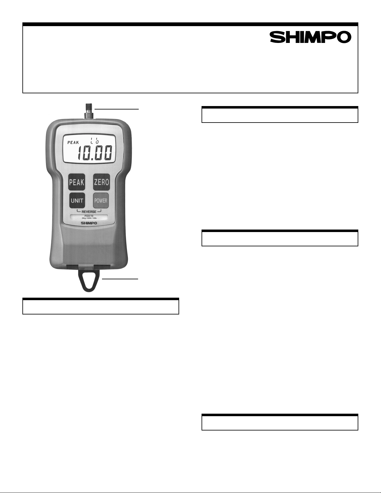
You have just received one of the world's smallest, rugged,
economical and versatile force gauges; its ergonomic de-
sign makes this gauge a friendly instrument to the human
hand. With just the touch of a button you can measure force
in any engineering units desired, i.e. lbs, kgs or N. Any
force from a few oz. up to 100 lbs can be accurately measured with one of the FGV family gauges. This series of fers
an RS232C and an analog output port for further processing the displayed measurements.
The unit's microprocessor enables it to measure forces very
accurately in the "average" or "peak" mode. Its LCD dis-
play is smartly designed to inform the operator at all times
of exactly what is going on.
If the hanger is used or the gauge is placed on a test stand,
reversing the display so that it can be read right-side-up is
simple: press only two buttons and the digits and units indicators reverse themselves instantly.
-0.5 — FGV-0.5 — FGV
-0.5 — FGV
-0.5 — FGV-0.5 — FGV
SHAFT
HANGER
-100-100
-100
-100-100
Instruction ManualInstruction Manual
Instruction Manual
Instruction ManualInstruction Manual
PP
recautionsrecautions
P
recautions
PP
recautionsrecautions
Do not use the gauge in hostile environments:
A.High humidity areas
B. High temperature environments
(see specifications table)
C. Caustic areas where various chemicals can seep into
the unit.
When not in use, place gauge back in its case to prevent
any damage due to an accidental drop etc. With a little care
you can have an instrument that can last and provide ser-
vice for many years.
OperationOperation
Operation
OperationOperation
When the carrying case is opened make sure you have all
the accessories that come with the instrument.
1. Charge the batteries for approx. 12 hrs. before using the
gauge (batteries come discharged from the factory).
When batteries are charging the BAT indicator is ON.
When the batteries are fully charged the indicator goes
OFF.
2. Hand tighten appropriate attachment to unit's measuring
shaft (do not use a wrench or any other device to tighten
the attachment).
3. Press the POWER switch and release. On the release of
the switch the display will momentarily show all 8's (digit
segment self-check) and then will show some zeros with
the last one or two digits changing to some random num-
bers. Also the unit of measurement (lbs, kgs or N) will
appear above the digits and stay as long as the instru-
ment is on.
Change Display UnitsChange Display Units
Change Display Units
Change Display UnitsChange Display Units
To change the display units, just press the UNIT button and
the units will change every time this particular button is
pressed.
1
Page 2
RR
everse the Displayeverse the Display
R
everse the Display
RR
everse the Displayeverse the Display
Low BatteryLow Battery
Low Battery
Low BatteryLow Battery
If unit is used with the hanger or mounted on a test stand
and the display must be reversed, follow this procedure:
1. Press the POWER switch and hold it; display will go
blank.
2. Press and hold UNIT switch.
3. Release POWER switch while you are still holding the
UNIT switch; display is still blank.
4. Press the POWER switch once more and release it while
still holding the UNIT switch. At this point you should
see the display reversed.
5. Release the UNIT switch; the display stays in that mode.
If you want to go back to the normal mode, repeat steps
1 through 5.
Select ASelect A
Select A
Select ASelect A
If you want to measure force in real time (average) the display will show just the digits and units of the force being
measured. If you want to measure "peak" force:
1. Press the PEAK button and the word PEAK will
appear in the upper left corner of the display.
2. The display will freeze after capturing the peak force.
3. Press ZERO to cancel previous peak and continue with
your tests.
If you want to go back to average mode press the PEAK
button again and the word PEAK will disappear from the
display.
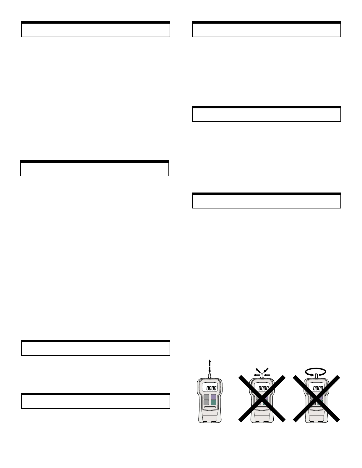
NOTE: It is very important that you measure forces (ten-
sion or compression) that are in line with the measuring
shaft and not at any angle (see fig. 1). Failure to observe
this directive will damage the instrument. Also, after the
gauge is positioned and ready to take a measurement (with
the proper attachment in place) tare the unit by pressing the
ZERO switch. In the PEAK mode to clear the display for
another measurement, press the ZERO switch.
verage or Pverage or P
verage or P
verage or Pverage or P
eakeak
eak
eakeak
When the battery charge starts to get low, a LO BAT sign
appears in the upper left corner of the display . At this point,
if necessary, the adapter/charger can be used to power the
unit indefinitely . With the power off it takes approx. 12 hrs.
to fully char ge. When the battery is fully charged the adapter/
charger cuts off completely to protect the battery.
AA
uto Puto P
A
uto P
AA
uto Puto P
If the power on the gauge is turned on and there is no activity for 10 minutes, the power is automatically cut-off to
conserve battery char ge. One minute before cut-off, the sign
PWR appears above the display digits to remind the operator that there is 1 minute left before power cut-off. If the
adapter/charger is powering the gauge, the Auto Power CutOff function becomes inactive.
TT
racking Fracking F
T
racking F
TT
racking Fracking F
A tracking function has been introduced to check and compensate for temperature drift. When measuring very minute
forces (a few oz.) and at a very slow rate, you may want to
turn off the tracking function. To turn the tracking function
on or off, follow the steps below:
1. Turn POWER off.
2. Press PEAK and UNIT switches simultaneously and hold
these until step 3 is complete.
3. Press POWER switch and release it to turn the power
on. If tracking function was on, the display will show
TRK OFF momentarily.
4. Release buttons PEAK & UNIT. The tracking function
is now off. Repeat above steps to turn it on. It is a good
idea to have this function on all the time unless it is absolutely necessary to cancel it.
ower Offower Off
ower Off
ower Offower Off
unctionunction
unction
unctionunction
Measure TMeasure T
Measure T
Measure TMeasure T
To measure tensile force use the hook attachment. The display will show the force measured and a minus sign (-) will
appear on the left of the display (right next to the digits).
Measure CompressionMeasure Compression
Measure Compression
Measure CompressionMeasure Compression
To measure compression force use the proper attachment.
No sign will appear on the left of the display during a com-
pression measurement.
2
ensionension
ension
ensionension
Fig. 1
Page 3

DimensionsDimensions
Dimensions
DimensionsDimensions
OverloadOverload
Overload
OverloadOverload
Even though each model is able to withstand an overload
of 200% of its rated capacity, caution should be exercised
that this does not happen very often otherwise the sensor
will be damaged. To protect the gauge and/or the sample
under test when a motorized stand or some other motorized device is used in conjunction with the gauge, two
overload output OC NPN transistors are available to be
used to disconnect power when the overload condition
reaches 120% of the gauge's rated capacity . One transistor
is for tension and the other for compression. See diagram
below (Fig 2).
RS232C PRS232C P
RS232C P
RS232C PRS232C P
The most important feature of the FGV family of gauges is
the availability of the RS232C communications port. Data
and commands can be linked to a PC or any other device
responding to RS232C signals for storage or further analy-
sis. Table 1 (below) describes the function of each pin of
the connector (HR12-10RC-10SDL) shown in Fig. 3.
PIN# DESCRIPTION
1 Analog signal output
2 Analog GND
3 Receive data (input)
4 Digital GND
5 Communication enable
6 Transmit data (output)
7 No connection
8 Compression overload output
9 Tension overload output
10 Frame GND
RS232C Output Specifications
Baud rate: 2400 bps
Data length: 8 bits
Parity: None
Stop bit: One
Logic level: ± 10 V
ortort
ort
ortort
Table 1
Fig. 2
Analog OutputAnalog Output
Analog Output
Analog OutputAnalog Output
An analog output signal is available for recording purposes.
The amplitude of this signal is ± 1 VDC. The voltage is
positive when compression testing is performed and negative for tension.
Signal Characteristics:
Amplitude: ± 1 VDC
Generated by: 12-bit D/A converter
Signal update: 140 times/sec
Load impedance: 10 KΩ minimum
Connector pins: Pin #1 signal output (analog)
Pin #2 GND (analog)
(see Fig.3 & Table 1)
NOTE: When the zero switch is pressed to tare the gauge
the analog output goes to 0V automatically.
(HR12-10RC-10SDL), HIROSE
ConnectionsConnections
Connections
ConnectionsConnections
FGV Output RS232C Connector
connector pin# on PC (D-sub 25pin)
3 (RxD) 2 (TxD)
6 (TxD) 3 (R xD)
4 (GND) 7 (GND)
5 (Enable) 4 (RTS)
Fig. 3
5 (CTS)
3
Page 4

Commands/RCommands/R
Commands/R
Commands/RCommands/R
esponsesesponses
esponses
esponsesesponses
The FGV series of force gauges has the ability to recognize
and respond to various commands from outside peripherals. If
for instance the gauge receives a legitimate command from a
PC, it will respond by sending back the same code indicating
to the PC that the command was recognized. If for example the
command is a request for average data output, it will send the
data and the code NA etc. If the gauge recognizes an error
while it is receiving a command, an error symbol is transmitted
back to the PC indicating the exact nature of the error.
Commands to FGV Gauge
AAcr: Tare
ABcr: Stop output
ACcr: Change to peak mode
ADcr: Change to average mode
AEcr: Peak reset
AFcr: Change units to kg (g)
AGcr: Change units to N
AHcr: Change units to lb (oz)
BAcr: Data output request
BBcr: Continuous data output request (10 times/sec)
BCcr: Model name confirmation request
BDcr: Units confirmation request
BEcr: Peak data output request
Response from FGV Gauge
NA!!!!!! cr: Average data output
NB!!!!!!cr: Peak data output
4-digit number with decimal point
sign (+ or –)
NE!!cr: Model number
02 03 04 05 06 07 08 09
FGV-0.5 FGV-1 FGV-2 FGV-5 FGV-10 FGV-20 FGV-50 FGV-100
NH!cr: Unit
0 1 2
N Kg (g) lb (oz)
Error symbols:
OBcr: Command error
ODcr: Overload error
OEcr: Parity error
OFcr: Format error
OGcr: Summing error
OHcr: Overrun error
CalibrationCalibration
Calibration
CalibrationCalibration
Required for Calibration:
1. A secure calibration stand to mount a force gauge upsidedown.
2. The appropriate calibration weight for your force gauge:
MODEL WEIGHT
FGV-0.5 200g
FGV-1 500g
FGV-2 1Kg
FGV-5 2Kg
MODEL WEIGHT
FGV-10 5Kg
FGV-20 10Kg
FGV-50 20Kg
FGV-100 50Kg
Calibration Procedure:
1. Turn POWER off.
2. Mount the force gauge upside-down on the calibration stand.
3. Attach the hook on the sensing shaft of the force gauge.
4. Press and hold the UNIT, PEAK and ZERO switches.
5. Press and release the POWER switch (while continuing to
press UNIT, PEAK and ZERO) until the smaller characters
at the top area of the display show CAL. Release the UNIT,
PEAK and ZERO switches. The force gauge is now in cali-
bration mode.
6. Press the UNIT switch. The display will show ZER. The
force gauge is now ready for zero point calibration.
7. Press ZERO to zero point calibrate. Wait 5 seconds. The
display will change to show PEK. Do not press any other
switches or move the sensing shaft during calibration.
8. Hang the calibration weight on the hook and stabilize; the
larger characters on the display will change. The force gauge
is now ready for full scale calibration.
9. Press the PEAK switch to begin full scale calibration. Do not
press any other keys or touch the weight during calibration.
After approximately 5 seconds the display will show END.
10. Press the UNIT switch. If calibration was successful, the
display will show OK momentarily , then automatically power
off. If calibration was unsuccessful, the display will show
ERR. Remove the calibration weight and repeat the procedure from step 6.
SpecificationsSpecifications
Specifications
SpecificationsSpecifications
FGV-0.5
FGV-0.5 FGV-1
FGV-1 FGV-2
FGV-2 FGV-5
FGV-5 FGV-10
FGV-10 FGV-20
FGV-20 FGV-50
FGV-50 FGV-100
MODELS
MODELS
FGV-0.5FGV-0.5
FGV-1FGV-1
FGV-2FGV-2
FGV-5FGV-5
FGV-10FGV-10
MODELSMODELS
8 oz
16 oz
2 lb
CAPACITY
CAPACITY
CAPACITYCAPACITY
RESOLUTION
RESOLUTION
RESOLUTIONRESOLUTION
ACCURACY
ACCURACY ±0.2% FS plus 1/2 digit at 73°F (23°C)
ACCURACYACCURACY
AVERAGE/
AVERAGE/
AVERAGE/AVERAGE/
PEAK MODE
PEAK MODE
PEAK MODEPEAK MODE
LOW BATTERY
LOW BATTERY
LOW BATTERYLOW BATTERY
INDICATION
INDICATION
INDICATIONINDICATION
SAMPLING
SAMPLING
SAMPLINGSAMPLING
OVERLOAD
OVERLOAD 200% of FS
OVERLOADOVERLOAD
AUTO POWER
AUTO POWER
AUTO POWERAUTO POWER
BATTERY
BATTERYBATTERY
RECHARGE
RECHARGE
RECHARGERECHARGE
TEMPERATURE
TEMPERATURE 32° - 104°F (0° - 40°C)
TEMPERATURETEMPERATURE
DIMENSIONS
DIMENSIONS 5.1"L x 2.9"W x 1.5"H (130 x 75 x 38)mm
DIMENSIONSDIMENSIONS
OVERLOAD
OVERLOAD
OVERLOADOVERLOAD
ACCESSORIES
ACCESSORIES
ACCESSORIESACCESSORIES
(INCLUDED)
(INCLUDED)
(INCLUDED)(INCLUDED)
ACCESSORIES
ACCESSORIES
ACCESSORIESACCESSORIES
AVAILABLE
AVAILABLE
AVAILABLEAVAILABLE
200 g
500 g
2 N
0.01 oz 0.001 lb 0.01 lb 0.1 lb
0.1 g
0.001 N 0.01 N 0.1 N
DISPLAY
DISPLAY 4-Digit LCD 12mm high. Reversible by a push of a button. Minus sign for tension.
DISPLAYDISPLAY
Yes (selectable)
Yes
DISPLAY
DISPLAY
DISPLAYDISPLAY
0.3 second
UPDATE
UPDATE
UPDATEUPDATE
35 times per second
RATE
RATE
RATERATE
POWER
POWER Rechargeable Ni-Cad batteries or AC through adapter/charger
POWERPOWER
OUTPUT
OUTPUT RS232C and ±1VDC (through a 12 bit D/A converter)
OUTPUTOUTPUT
Yes (not active if adapter/charger is in use)
OFF
OFF
OFFOFF
BATTERY
20 hrs. when fully charged
CHARGE
CHARGE
CHARGECHARGE
12 hrs. approx.
TIME
TIME
TIMETIME
WEIGHT
WEIGHT 1lb (450g)
WEIGHTWEIGHT
One NPN OC transistor for tension, one NPN OC transistor for compression
OUTPUT
OUTPUT
OUTPUTOUTPUT
AC adapter/charger, carrying case, hook ,chisel, flat head, notched head, hanger,
cone head, extension rod and analog output cable.
Test stands, RS232C cable, overload cable.
1000 g
5 N
5 lb
2 Kg
10 N
20 N
1 g 0.001 Kg 0.01 Kg
10 lb
5 Kg
50 N
FGV-20FGV-20
20 lb
10 Kg
100 N
FGV-50FGV-50
50 lb
20 Kg
200 N
FGV-100
FGV-100FGV-100
100 lb
50 Kg
500 N
4
SHIMPO INSTRUMENTS 1701 Glenlake Avenue, Itasca, IL 60143 USA "
#
(630) 924-7138 FAX (630) 924-0342
 Loading...