

Page 1
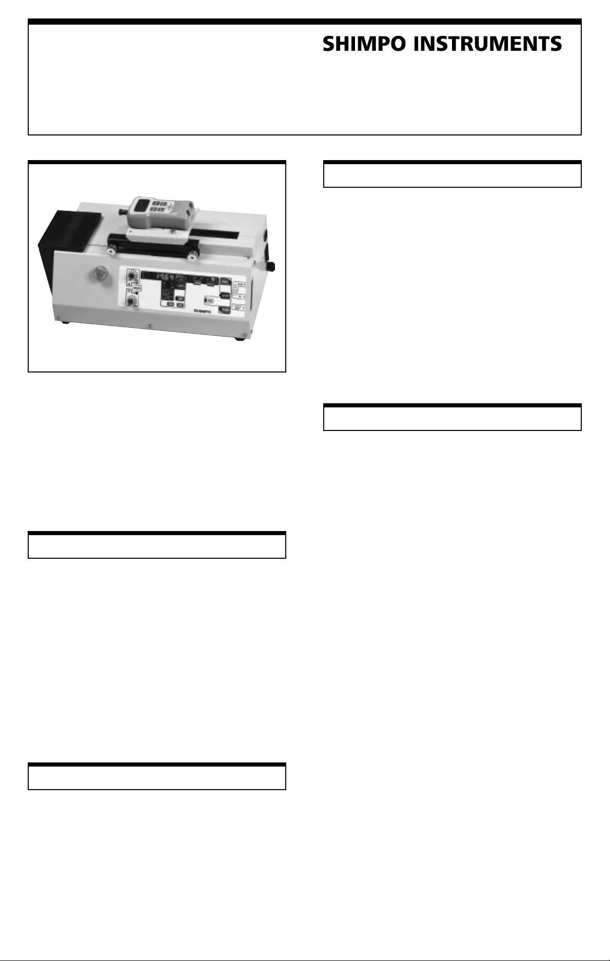
Models FGS-50PXH
& FGS-50PXL
Programmable Motorized
Test Stand
Congratulations on your purchase of a Shimpo FGS-PXH or
FGS-50PXL motorized test stand. W e trust you will enjoy many
years of professional results from your Shimpo stand.
Please read the entire instruction manual thoroughly before initial
set-up and operation; the information contained herein will aid
you in operating your Shimpo stand safely and with excellent
results.
If you have any questions regarding our product(s), call your
local Shimpo representative or contact Shimpo directly for
assistance.
Features and Benefits
Shimpo's FGS test stands are designed for a variety of tensile
and compression force testing (up to 110 pounds) and feature:
• All steel construction guarantees durability and stability
for production, laboratory and quality contr ol applications
• Dual speed controls are optimally positioned to adjust test
and return travel rates of the drive assembly
• Drive assembly accepts an optional universal mounting
plate, enabling the interfacing of a large selection of force
gauge models (contact Shimpo for specific models)
• 4½ digit LED display indicates displacement or rate of
the drive assembly
• Analog output (labeled “Length Out”) is convenient for
data acquisition requirements
Inspection
If any shipping damage occurs, do not unpack test stand. Notify
shipping carrier immediately for damage claim instructions.
Refer to nameplate to con firm model number ordered and
record serial number for future reference. Items included with
test stand are:
• (3) M5 x 6 and (4) M4 x 8 screws
• (1) 5mm Allen wrench
Instruction Manual
Important Safety Instructions
• Position test stand on a level, heavy-duty and vibration
free table
• Confirm that the test stand case is properly grounded to
the AC line
• Keep hands, hair and jewelry away from stand when drive
assembly is in motion
• Operate the membrane keypad with care; do not use sharp
objects that may puncture the overlay
• Ensure that AC power is removed from test stand before
making any adjustments
• If LED indicates drive assembly has been overloaded,
immediately turn the power switch to the off position and
remove the overload condition (wait at least two minutes
before reapplying power to the test stand)
Set-Up
1. Plug in line cord and turn on power switch located on rear
of stand. All display segments and LEDs will execute a
power-up self test for two seconds. After the self test, the
4-digit display defaults to length which is displayed in
inches (0.00).
2. Metric units (mm) can be obtained by changing a dip
switch. The dip switches to control the measurement units
(switch #1) or the home position (switch #2) are located at
the top of the cutout for the cable ports in the side of the
stand (see page 2, display panel diagram, #27). It is possible
to raise and lower these switches using a small instrument
(such as a mini screwdriver). The stand must be reset
(turned off and on) whenever one of these switches is
changed.
NOTE: When dip switch #1 is in the up position, the stand will
display inches (0.00); when in the down position, it will display
millimeters (00.0). When dip switch #2 is in the down position
the upper manual limit switch is the home location. When in the
up position the lower manual limit switch is the home position.
Mounting Shimpo Force Gauges
With the 5mm Allen wrench, remove the mounting plate from
the test stand. For the FGE/FGV series use four M4 x 8 mounting
screws (supplied with stand) when mounting force gauge to
mounting plate. When mounting DFS series use three M5 x 6
screws (supplied with stand) to mount force gauge to mounting
plate. Reinsert mounting plate to test stand.
NOTE: Nearly all manufacturers' gauges are compatible with
the FGS-50PXH and FGS-50PXL when used in conjunction with
the optional UNI-Plate.
Page 2
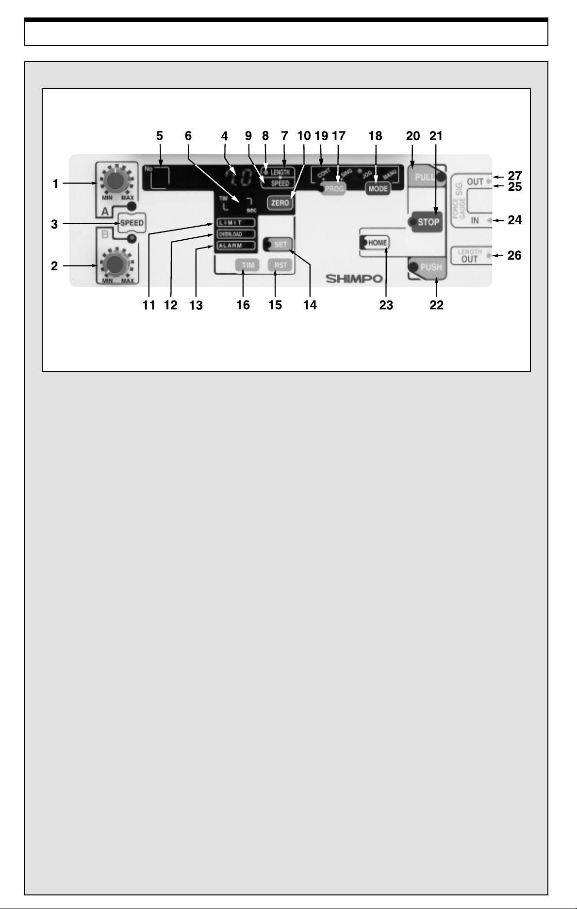
Display Panel
1. Speed A control knob: Changes the A speed of the force gauge plate
2. Speed B control knob: Changes the B speed of the force gauge plate
3. Speed select switch: Selects which speed control knob (A or B) is active
4. Movement distance/speed/cycle count display: Indicates movement distance/speed/number of cycles performed
5. Programmed point display: Displays program point (0-9)
6. Stop time display: Displays stop time when operating a program or cycle
7. Movement distance/speed/cycle count switch: Selects whether distance/speed/number of cycles performed is displayed
8. LED distance indicator: Indicates if distance is being displayed
9. LED speed indicator: Indicates if speed is being displayed
10. Zero switch: Resets distance measurement to zero
11. Limit switch LED: Indicates if one of the manual limit switches has been tripped
12. Overload LED: Indicates if the force gauge has been overloaded
13. Motor alarm LED: Indicates if the stand’ s motor has been overloaded
14. Program setting switch: Set program points
15. Setting reset switch: Clear and/or cancel a set point
16. Time set switch: Selects stop time for a program or cycle
17. Program switch: Selects a single program or a cycle program
18. Mode switch: Selects standard, jog, single cycle, or continuous cycle operation
19. Movement display LED: Displays type of mode or program operation
20. Pull switch: Begins movement in “pull” direction
21. Stop switch: Stops movement
22. Push switch: Begins movement in “push” direction
23. Home switch: Returns gauge to either the upper or lower manual limit switch
24. Force gauge input connector: Permits communication between digital gauges and the test stand
25. Force gauge output connector: Permits transfer of data from FGV series to computer when FGV is connected to the stand
26. Distance output connector: Permits connection for analog output voltage for distance/displacement measurement
27. English to Metric and home position dip switches (within communications cutout)
Page 3

Operation
Drive Assembly Control
Speed controls A & B can easily be adjusted and assigned to control
the test and return travel rates of the force gauge. The position of
the LED (A or B) determines which control is active.
The upper and lower travel limits can be adjusted by loosening
the thumb limit screws and sliding them to the desired position.
NOTE: Don’t forget to hand tighten the limit screws when the
desired position is reached.
Operating Procedures
The FGS-50PXH and FGS-50PXL feature two types of operation:
• Mode Operation
• Program Operation
Mode Operation
By pressing the “mode” button the LED will change between
four basic types of operation:
1. MANU - Stand moves in either the “push” or “pull” direction
(depending on the button depressed) and will continue to move
in direction selected until “stop” is pushed or until one of the
two manual switches are tripped.
2. JOG - Moves in either the “push” or “pull” direction as long as
the corresponding button is being depressed.
3. SING - Performs single cycles between the upper and lower
manual switches. The length of pause time (1-5 seconds) c an
be selected by depressing the “tim” button. The speed for the
“pull” direction will always be setting “A” and the “push”
dir ec t io n setting “B ” ( th e stand switches automatically). The
stand can run either compression or tension cycles, depending
on which direction the stand is in itially directed. The total
number of cycles run can be obtained by depressing the “length/
speed” button until there is no LED showing.
4. CONT - Same as the SING mode, except that the stand will
continuously cycle between the upper and lower manual
switches.
Program Operation
Before initiating the program mode it is best to adjust the speed
settings until each are at satisfactory levels.
The program will begin from the "home" position. The factory
setting for the home position is the upper manual limit switch.
NOTE: When dip switch #2 is in the down position the upper
manual limit switch is the home location. When in the up
position, the lower manual limit switch is the home position.
By pressing the “prog” button the LED will move between the
two types of program operation:
1. SING - The stand will run a single program.
2. CONT - The stand will continuously cycle through the
program.
The test stand is programmed as follows:
1. Press "home". This will be the starting position of the
program.
2. After selecting one of the two programs, press the “set”
button. The LED number in the far upper left corner of
the display will show a flashing “0” followed by a flashing
"-----".
3. Using the “push” and “pull” buttons, move the stand into
position.
4. Select speed “A” or “B” using the “speed” button.
5. Select the amount of stop time (in seconds) by pressing
the “tim” button. The LED will scroll through 1,2,3,4,5,P
(“P” stands for pause; the program will pause at this
position until either “push” or “pull” are pressed to resume
the rest of the program).
6. Press the “set” button again to store this first point. The
LED number in the upper left corner of the display will
change to the next digit.
7. To set the next point simply repeat steps 2-5. The LED in
the upper left corner of the display can display numbers 0-9,
up to ten potential set points.
8. When all points have been programmed, press the “set”
button again to store the program.
9. Press either the "push" or "pull" button to begin the program.
10. To cancel a set point, press the “rst” button while in the
“set” mode; press “rst” once more to move the next
programmed point into position.
11. If “stop” is pressed while the program is at one of its stop
positions, the entire program is canceled.
12. T o erase the whole program you must scroll through each
set point and erase them individually.
Input & Output Ports
Three communication/data ports are located on the right side of
the test stand. Use these ports along with the appropriate cable(s)
(optional) to download information from a compatible force gauge
and upload information to a compatible data acquisition device.
PORT 1: FGC.V.X Input Port
DFS Series (Requires DFS-CTRLCABLE) - Receives
overload information from a DFS series gauge. If an overload
condition exists, the drive assembly will stop, thus preventing
permanent load cell damage. As an added feature, the test stand
will stop at force setpoints when the "hi" and "lo" limits are
programmed on the DFS.
FGV Series (Requires FGV-CTRLCABLE) - When interfacing
to a FGV series force gauge, the test stand will receive overload
and measuring data. If an overload condition exists, the drive
assembly will stop, thus preventing permanent load cell damage.
NOTE: The force gauge must be turned on (display showing)
for the overload protection feature to work.
PORT 2: FGC.V Output Port
(Requires FGV-RS232 cable) - Transmits RS232C data to an
external device when a FGV series force gauge is mounted to
the stand (this port is not needed for the DFS series).
PORT 3: Length Output Port
(Requires FGV-ANALOG cable) - Transmits an analog output
voltage proportional to the length meter display . The relationship
between output and display is 10mV/mm. Since the length meter
data is generated by the test stand, this port can be used with any
force gauge mounted to the stand.
NOTE: If the LED display shows rate (mm/min), the voltage
output will still reflect length meter data.
Page 4

Troubleshooting
The stand does not turn on:
• Check all electrical components (power source, power cord, fuse, power switch, emergency cut-off switch)
The mounting plate (force gauge) does not move:
• Check manual limit switches and adjust accordingly
• Check to see if the full travel range has already been achieved
• Check to be sure you are in the correct operating mode
The stand will not accept my program:
• The mounting plate (force gauge) must be at the home position
Dimensions & Specifications
KEY:
mm
(in)
Model FGS-50PXH FGS-50PXL
Capacity 110 lb (50 kg)
Stroke 5.5" (140 mm)
Travel Speed Adjustable: 1.57-15.74"/min Adjustable: 0.39-3.93"/min
Display Four digit LED, 0.41" high (10.5 mm).
Power 120 VAC, 60 Hz
Weight 40 lb (18 kg)
OPTIONAL ACCESSORIES UNI-Plate, FGV-CTRLCABLE, FGV-RS232, FGV-ANALOG,
NOTE: The display ranges for length and rate are larger than what’s listed in the specifications. This is due to a
mechanical backlash which may occur if the drive assembly is subjected to excessive changes in direction.
(Horizontal - Standard) (Horizontal - Low Speed)
(40-400 mm/min) (10-100 mm/min)
Reads in inches (0.01 resolution) or millimeters (0.1 resolution)
DFS-CTRLCABLE, DFS-RS232 and DFS-ANALOG
Warranty
LIMITED EXPRESS WARRANTY: Shimpo Instruments warrants, to the original purchaser of new products only, that this product shall be free from defects in
workmanship and materials under normal use and proper maintenance for one year from the date of original purchase. This warranty shall not be effective if the product
has been subject to overload, misuse, negligence, or accident, or if the product has been repaired or altered outside of Shimpo Instruments’s authorized control in any
respect which in Shimpo Instruments’s judgment, adversely affects its condition or operation.
DISCLAIMER OF ALL OTHER WARRANTIES: The foregoing warranty constitutes the SOLE AND EXCLUSIVE WARRANTY , and Shimpo Instruments hereby
disclaims all other warranties, expressed, statutory or implied, applicable to the product, including, but not limited to all implied warranties of merchantability and fitness.
LIMITATION OF REMEDY: Under this warranty , Shimpo Instruments’ SOLE OBLIGATION SHALL BE TO REPAIR OR REPLACE the defective product or part, at
Shimpo Instruments’ option. Shimpo Instruments reserves the right to satisfy warranty obligation in full by reimbursing Buyer for all payments made to Shimpo Instruments,
whereupon, title shall pass to Shimpo Instruments upon acceptance of return goods. To obtain warranty service, Purchaser must obtain Shimpo Instruments’ s authorization
before returning the product, properly repackaged, freight pre-paid to Shimpo Instruments.
INDEMNIFICATION & LIMITATION OF DAMAGES: Buyer agrees to indemnify and hold Shimpo Instruments harmless from and against all claims and damages
imposed upon or incurred arising, directly or indirectly, from Buyer’ s failure to perform or satisfy any of the terms described herein. In no event shall Shimpo Instruments
be liable for injuries of any nature involving the product, including incidental or consequential damages to person or property, any economic loss or loss of use.
MERGER CLAUSE: Any statements made by the Seller’s representative do not constitute warranties except to the extent that they also appear in writing. This writing
constitutes the entire and final expression of the parties’ agreement.
 Loading...