

Page 1

FGS-250PV Series Flex-StandFGS-250PV Series Flex-Stand
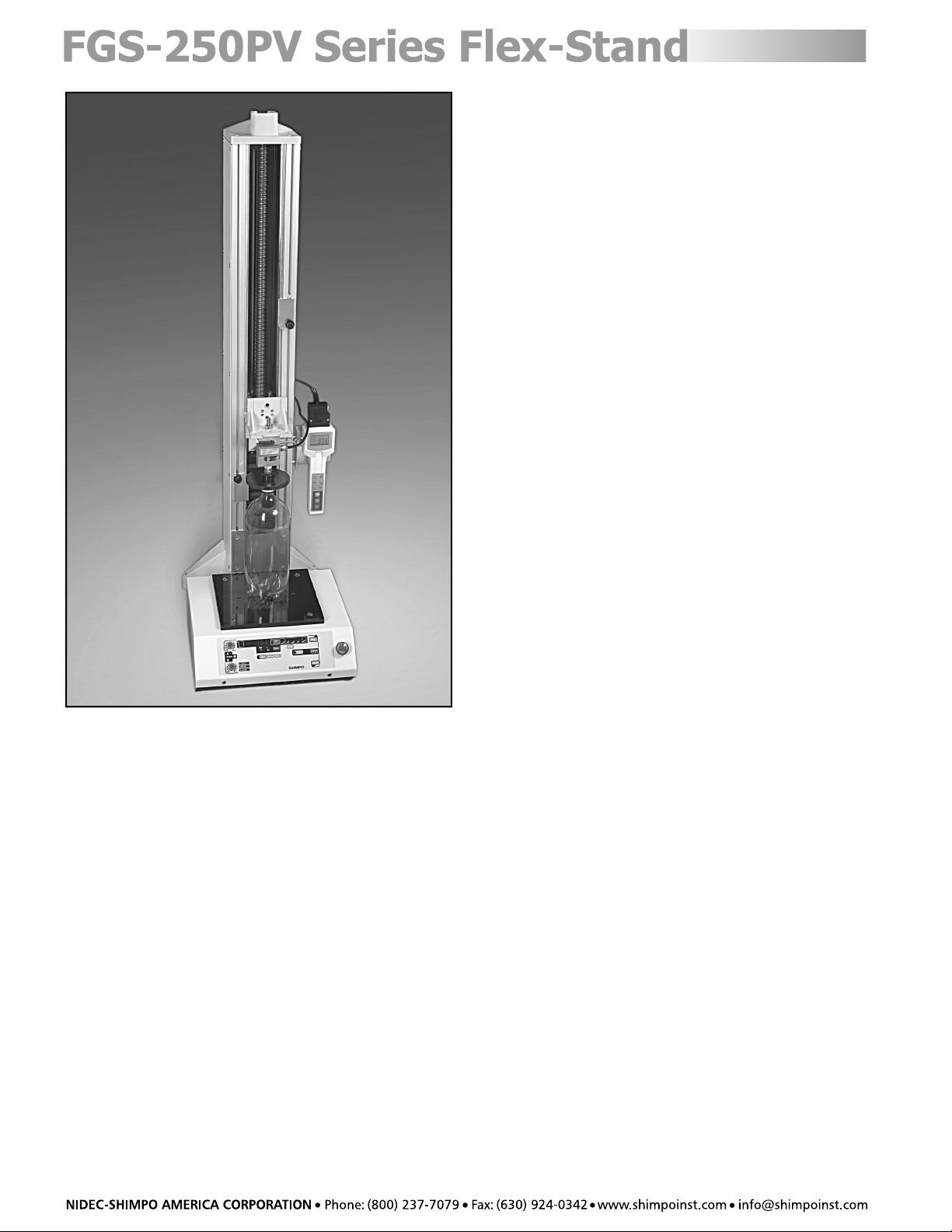
FGS-250PV Series Flex-Stand
FGS-250PV Series Flex-StandFGS-250PV Series Flex-Stand
Instruction Manual
Page 2
Contents
Inspection/Standard Accessories .................................. 3
Features and Benefits .................................................. 3
Important Safety Precautions ...................................... 3
Display Panel ................................................................ 4
Terminals & Switches ....................................................5
Set-Up .......................................................................... 5
Operation .................................................................... 6
Setting a Force Limit .............................................. 6
MANU (Manual) .....................................................6
JOG (Jog) ............................................................... 6
SING (Single) .......................................................... 6
CONT (Continuous)................................................7
PROG (Program Operation) ................................... 7
RS232C Output Format ................................................ 9
Attaching Gauges ........................................................9
Congratulations on your purchase of a Shimpo
FGS-250PVH, FGS-250PVM and/or FGS-250PVL
programmable motorized test stand. We trust you will
enjoy many years of professional results from your
Shimpo product.
Please read the entire instruction manual thoroughly
before initial set-up and operation; the information
contained herein will aid you in operating your Shimpo
programmable motorized test stand safely and with
excellent results.
If you have any questions regarding our product(s), call
your local Shimpo representative or contact Shimpo
Instruments directly for assistance.
Attaching a Force Gauge to the
Force Gauge Plate .................................................9
Modifying the Force Gauge Plate
for Load Cell Use ................................................. 10
Attaching the DRI Force Gauge Plate
and Force Gauge ................................................. 10
Dimensions and Specifications ................................... 11
Troubleshooting ........................................................ 12
Warranty .................................................................... 12
2
Page 3
Inspection/Standard Accessories
If upon delivery, shipping damage is detected, do not
operate the unit. Notify shipping carrier immediately
for damage claim instructions. Refer to nameplate and
record the serial number for future reference.
Items included with the FGS-250PVH, FGS-250PVM or
FGS-250PVL are:
• (1) Force gauge attachment plate
• (1) DRI mounting plate and fasteners
• (1) Table plate
• (4) M6x14 socket bolts
Important Safety Precautions
Always wear eye protection when testing
materials.
When programming forces in the continuous
mode, ensure that the force values are
programmed correctly (example: -5; Hi limit is
greater than -25; Low limit).
Do not store in oily, dusty, humid or wet areas.
Features and Benefits
Shimpo’s FGS-250PVH, FGS-250PVM or FGS-250PVL
Flex-Stand offers many features and benefits, including:
• User programmable set points: speed, distance, stop
time permit custom, automated testing
• Zero load programmability allows user to set
distance from when force is first detected
• High and low force settings permit non-destructive
testing
• Programmable cycling allows running a
predetermined number of cycles and/or cycle
between force setpoints
• 31 inches of travel enable testing of large samples
or applications requiring extremely long travel
ranges
• Compatibility with nearly all manufacturer's gauges
enables flexibility in testing applications
• Gauge overload protection prevents downtime
waiting for repair
• RS232 and analog distance outputs allow graphing
and analysis of data
• High, standard, and low speed models available for
rapid and precise testing applications
• Manually adjustable upper and lower distance limits
restrict movement for precise testing
• Solid all steel construction contributes to precision
movement
• English and metric units of measure ensure
adaptability to all testing requirements
Position test stand on a level, heavy-duty table.
Confirm that the test stand case is properly
grounded to the AC line.
Keep hands, hair and jewelry away from stand
when drive assembly is in motion.
Operate the membrane keypad with care; do
not use sharp objects that may puncture the
overlay.
Ensure that AC power is removed from test
stand before making any adjustments.
If ALARM LED indicates drive assembly has been
overloaded, immediately press the emergency
stop switch. Reset the emergency stop switch,
reverse the direction of travel and turn the
power switch to the “off” position. Wait at
least two minutes before reapplying a load and
turning the power back on.
3
Page 4
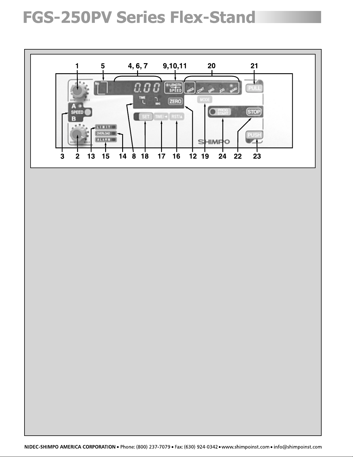
Display Panel
NO.DESIGNATION
1. A SPEED Control
2. B SPEED Control
3. SPEED: Selects speed control knob A or B. (Indicated w/red LED)
4. LENGTH, SPEED or CYCLE Display: Displays length, speed or cycle of a program when power is on.
(Note: Cycle Display can only be selected in mode SING, CONT or PROG)
5. No: Displays program point or step (0-5)
6. !: Indicates high limit value in all modes
7. ": Indicates low limit value in all modes
8. TIME: Displays user selected delay time between program cycles
9. LENGTH, SPEED or CYCLE: Selects display of length, speed or cycle of a program
10. LED LENGTH Indicator: Indicates that length is being displayed. (w/Red LED)
11. LED SPEED Indicator: Indicates that speed is being displayed. CYCLE display is indicated when both Length and
Speed LED’s are off
12. ZERO: Resets length measurement to zero
13. LIMIT LED: Indicates one of the manual limit switches has been tripped
14. OVERLOAD LED: Indicates that the force gauge has been overloaded
15. ALARM LED: Indicates test stand’s motor has been overloaded
16. RST/!: Changes the increment point upward
17. TIME/#: Changes digit position when programming force limits; also changes delay time between cycles
18. SET: Stores a program cycle to a value that the user selects using RST/! and TIME/#
19. MODE: Selects mode of operation. (Manual [MANU], Jog [JOG], Single[SING], Continuous [CONT] or Program [PROG])
20. Operation Display: Informs user of current mode of operation
21. PULL: Test stand moves in an upward direction
22. STOP: Stops test stand movement
23. PUSH: Test stand moves in a downward direction
24. PROG START: Start the program
4
Page 5

Terminals & Switches
NO.DESIGNATION
1. Emergency Stop
2. Plug receptacle for force gauge
3. Power Switch
4. Power Cable
5. OUT: Permits transfer of force data from FGV, DFS or DRI series of force gauges and distance data from
programmed set points
6. IN: Permits communication between digital gauges and the test stand
7. LENGTH: Permits connection for analog output voltage related to distance
Set-Up
Connect all cables and power cords before applying
power to the test stand and force gauge. Apply power
to the force gauge before applying power to the test
stand; this is necessary so that the test stand will
recognize which Shimpo force gauge is being used.
To identify whether the stand is in metric or English units,
turn the power on (power SW is located in the back of
the unit); metric units will display one decimal place (0.0),
while English units display two decimal places (0.00).
To switch from English to metric units, push “SPEED” and
“RST/!” switches while turning the power on. To return
to English units, turn the test stand off, then push
“SPEED” and “TIME/$” switches while turning the power
back on.
5
Page 6

Operation
There are five modes of operation: MANU (Manual),
JOG (Jog), SING (Single). CONT (Continuous) or
PROG (Program). The user can select one of these
modes by pressing the “MODE” button until the desired
mode of operation is illuminated.
In this mode of operation the user can display length or
speed. Display length by pressing the “LENGTH/SPEED”
button until the LED adjacent “LENGTH” is illuminated.
To display speed, push the “LENGTH/SPEED” button until
the LED adjacent “SPEED” is illuminated.
It is possible to restrict the range of travel with manual
limits. To manually adjust distance limits, loosen each of
the two set screws holding the limit switch brackets; these
set screws/brackets prevent the force gauge or load cell
platform from traveling by activating internal limit
switches. Adjust the top set screw/bracket to set the
upper distance limit and the bottom set screw/bracket
to set the lower distance limit.
Setting a Force Limit
It is possible to set one force limit when using a Shimpo
DFS, DRI or FGV force gauge with the appropriate cable
and operating the test stand in the manual, jog, single,
and program mode. To program a force limit (when in
one of these modes), press the “SET” button on the front
panel display. Note that the display “No” box shows
“Fv”. The “F” and the two arrows inform the user that
he will be programming a force limit. Use the “TIME/#”
to change digit position and “RST/!” to increment each
digit until the desired limit force is displayed. Press the
“TIME/#” button until no digits are blinking. This allows
the user to select a negative sign by pressing the “RST/!”
button. With no negative sign displayed, the test stand
force limit is programmed as a compression force limit;
with the negative sign displayed, the test stand force
limit is programmed as a tension force limit. Press “SET”
to store the force limit in memory.
The manual, jog, and single modes share the same
programmed force limit.
Two force limits can be set when operating in the
continuous mode. The instructions for programming
two force limits are located in the Operation section under
CONT (Continuous) on page 7.
MANU (Manual)
Press “MODE” button until “MANU” LED is illuminated.
This mode of operation is ideal for manually recording
force measurements. The test stand will only operate
between the limits that are set by the test stand user.
These limits can be either manually adjusted (distance
limits) or programmed with force limits when a Shimpo
force gauge is used (see the “Setting a Force Limit” section
above for force limit programming details).
The test stand will move in the downward or upward
direction when the respective “PUSH” or “PULL” button
is selected. The stand will continue to move in the
selected direction until one of the following occurs: the
“STOP” button is pushed, one of the manual limit switches
is tripped, the emergency reset button is pushed or the
force limit is reached.
NOTE: In this mode of operation, no RS232C output is
produced.
JOG (Jog)
Press MODE button until “JOG” LED is illuminated.
This mode of operation is identical to “MANU”, except
that the movement in any direction will only occur while
either the “PUSH” or “PULL” button is depressed.
See the “Setting a Force Limit” section (left) for force
limit programming details.
NOTE: In this mode of operation, no RS232C output is
produced.
SING (Single)
Press MODE button until “SING” LED is illuminated.
This mode of operation is ideal for completing one cycle
between manual distance limits and/or force limit. The
initial starting direction can be either in the tension or
compression direction depending on whether the “PULL”
or “PUSH” buttons are pressed.
See the “Setting a Force Limit” section (left) for force
limit programming details.
The test stand will move downward or upward after
automatically zeroing the force value of the Shimpo gauge
when the respective “PUSH” or “PULL” button is selected.
The stand will continue to move until one of the following
events occurs: the “STOP” button is pushed, one of the
manual limit switches is tripped, the emergency reset
button is pushed or the force limit is reached. If the stand
is stopped for any of these reasons, the gauge’s value will
be reset to zero once either the “PUSH” or “PULL” button
is pushed again to resume movement.
In this mode of operation, the user can display length,
speed or cycle count. Display length by pressing the
“LENGTH/SPEED/CYCLE” button until the LED adjacent
“LENGTH” is illuminated. To display speed, push the
“LENGTH/SPEED/CYCLE” button until the LED adjacent
“SPEED” is illuminated. Finally, to display cycle count,
press the “LENGTH/SPEED/CYCLE” button until there are
no LED’s illuminated. When the stand platform is moving
in the “down” direction, the LED next to “SPEED B” is
active; when the stand is moving in the “up” direction,
the LED next to “SPEED A” is active.
NOTE: An RS232C output is produced when using this
mode of operation; refer to “RS232C Output Format” on
page 9 for details.
6
Page 7

CONT (Continuous)
Press “MODE” button until “CONT” LED is illuminated.
This mode of operation is ideal if the user wants the test
stand to repeatedly cycle up and down continuously or
for a user-programmed number of times. The stand will
start in either direction depending on whether “PUSH”
or “PULL” is selected.
Length, speed or cycle count can be displayed as
described in the “SING (Single)” section on page 6.
NOTE: An RS232C output is produced when using this mode
of operation, refer to “RS232C Output Format” on page
8 for details.
To begin programming the test stand, press the “SET”
key; the display will indicate a “C” in the “No” box. The
“C” designates that the digits programmed into the
adjacent LED’s will determine the number of cycles (number
of times) a program will run. Using the “TIME/#” and
the “RST/!” buttons, select the number of cycles you
want the program to complete (0001-9999) or select four
“0’s” if you want the program to run continuously; press
“SET” to store the number of cycles.
The letter “Ft“ appears in the LED’s in the “No” box; this
informs the user that the upper force limit should be
programmed. Use the “TIME/#” and “RST/!” buttons to
select the desired force limit. Use “TIME/#” to change
digit position and “RST/!” to increment each digit until
the desired limit force is displayed. NOTE: Pressing the
“TIME/#” button until no digits are blinking allows the
user to select a negative sign by pressing the “RST/!”
button. With no negative sign displayed, the test stand
platform is programmed to move downward (this denotes
compression). With the negative sign displayed, the test
stand platform will move upward (this (-) denotes tension).
Press “SET” to store the upper force limit in memory. The
down arrow LED (Fu) will light indicating that the test
stand is ready to have its lower force limit programmed.
Program the force limit using the “TIME/#” and “RST/!”
buttons. Use “TIME/#” to change digit position and
“RST/!” to increment each digit until the desired limit
force is displayed. NOTE: The upper limit must be greater
than the lower limit (F
upper>Flower
; -5>-20). Again press
“SET” to store the lower force limit into memory.
You may delay the time between upward and downward
movements by selecting 0, 1, 2, 3, 4 or 5 seconds using
the “TIME/#” button. You may view distance traveled
by pressing “LENGTH/SPEED/CYCLE” until the LED
adjacent “LENGTH” is lit. Speed can be displayed by
pressing “LENGTH/SPEED/CYCLE” until the LED adjacent
“SPEED” is lit. Finally, the number of cycles completed
can be displayed by pressing “LENGTH/SPEED/CYCLE” until
no LED’s are lit.
The test stand will move downward or upward after
automatically zeroing the force value of a Shimpo gauge
when the respective “PUSH” or “PULL” button is selected.
The stand will continue to move until one of the following
events occurs: the “STOP” button is pushed, one of the
manual limit switches is tripped, the emergency reset
button is pushed or the force limit is reached. If the
stand is stopped for any of these reasons the gauge’s
value will be reset to zero once either the “PUSH” or
“PULL” button is pushed again to resume movement.
PROG (Program Operation)
Press the “MODE” key until the LED adjacent to “PROG”
is lit.
NOTE: An RS232C output is produced when using this
mode of operation, see “RS232C Output” section on
page 9 for details.
Before programming the stand, it is best to get the two
speed levels set appropriately. One should be set for the
speed the user wants their test performed at and the
other should be set at the highest acceptable level to have
the stand moving when not performing the actual force
test (this is usually at the maximum the stand will allow).
To begin programming the test stand, press the “SET”
key; the display will indicate a “C” in the “No” box. The
“C” designates that the digits programmed into the
adjacent LED’s will determine the number of cycles
(number of times) a program will run. Using the “TIME/#”
and the “RST/!” buttons, select the number of cycles
you want the program to complete (0001-9999) or select
four “0’s” if you want the program to run continuously.
Press “SET” to go to the next step.
See the “Setting a Force Limit” section on page 6 for
force limit programming details.
The display in “No” box now shows “H”; the “H”
designates the home position. Select the “PUSH” or
“PULL” button to set the HOME position; press “SET”.
The test stand platform will automatically move to the
appropriate (manually set) distance limit position.
The display in “No” box now shows “F”; the “F” designates
the auto zero function. This function is only available
when using the FGV or DRI Shimpo force gauges. Use
the “TIME/#” and “RST/!” buttons to program the “zero”
force.
NOTE: The recommended minimum zero force that the
user should program into the test stand is 0.2% of the
full scale (rating of the force gauge), i.e. if the
programmer is using an FGV-200H force gauge, the
programmed “zero” force should be 0.4 lb (0.002 X 200
= 0.4). If no force is programmed in this step and the
display reads all zeros, the test stand will not zero the
distance and this feature is inoperative. Press the “SET”
button to move on to the next step. This very useful
function allows the operator to reset the distance display
and RS232 output data to zero once the force gauge
senses a force measurement.
7
Page 8

The display in the “No” box now shows “t”, which
designates the tare function at “0” position. Select “on”
or “off” by pressing “RST/!” and press “SET”. The tare
function allows the use of fixtures/grips on the force
gauge and then setting the force gauge display to zero.
This function is useful as some fixtures/grips weigh more
than others and this function sets the display to zero
provided that fixture/grip does not weigh more than
50%* of the gauge’s capacity.
*NOTE: Shimpo recommends only taring approximately
20% of the gauge’s rated capacity; this guarantees that
the gauge’s full capacity will still be available for measuring.
The display in the “No” box shows “0”, and the “LENGTH/
SPEED/CYCLE” display shows “----”. The “0” designates
that the test stand begins each cycle from this position.
Using the “PUSH” or “PULL” buttons, adjust the test stand
to the position from which the force gauge will begin
force/distance tests. Select speed “A” or “B” (using the
“SPEED” button) at which the stand should return to
this zero position. A time delay (pause) up to 5 seconds
can be programmed between programmed points. Use
the “TIME/$” button to cycle through “0”, “1”, “2”, “3”,
“4”, “5” or “P”. If “P” is selected, the user must press
“PROG START” to restart the test stand program. Position
“0” is called the set point zero position; the test stand
will return to this position at the beginning of each
programmed cycle. The force gauge will also tell the
test stand to stop and return to set point 0 if a
programmed force limit is reached. If the force gauge
never reaches a programmed force limit, the test stand
will execute an entire cycle and return to the set point
zero position and then begin the next cycle. (To delete
an unwanted position press “RST/!”. Press the “SET”
key to move on to the next programming step.)
The display in “No” box shows “3” and the “LENGTH/
SPEED/CYCLE” display shows “----”. Repeat these steps
outlined in the above paragraph up to a maximum of 5
points. If no additional steps are desired, press the
“SET” key while the “LENGTH/SPEED/CYCLE” display
shows “----” to store the program.
Run the program by pressing “PROG START” on the display
panel.
To reset the program memory, press and hold “RST/!”
and then press “SET”. The display will read “CCCC”.
Length, speed or cycle count can be displayed as
described in the SING (Single) mode of operation section,
page 6.
The display in the “No” box shows “1” and the “LENGTH/
SPEED/CYCLE” display shows “----”. The “1” designates the
next position of a cycle that the test stand will move to;
this position is defined as set point 1. Using the “PUSH” or
“PULL” buttons, move the force gauge to position 1. Ensure
that the correct LED adjacent the “SPEED A” or “SPEED B” is
illuminated so that the test stand will travel at the intended
speed. NOTE: If the programmed force limit is detected by
the force gauge, the test stand will not move through the
entire programmed distance and the force gauge will return
to set point zero. Press the “SET” key.
The display in the “No” box shows “2, and the “LENGTH/
SPEED/CYCLE” display shows “----”. The “2” designates
the next position of a cycle that the test stand will move
to; this position is defined as set point 2. Using the “PUSH”
or “PULL” buttons, move the force gauge to position 2.
Ensure that the correct LED adjacent the “SPEED A” or
“SPEED B” is illuminated so that the test stand will travel
at the intended speed. NOTE: If the programmed force
limit is detected by the force gauge, the test stand will
not move the entire programmed distance and the force
gauge will return to set point zero. Press the “SET” key.
8
Page 9

RS232C Output Format
SING/CONT Mode
Counter Direction Force Distance
ZZ{Space}0003{Space}A{Space}-0021.5{Space}+032.8{Cr}
NOTE: Direction B: PUSH, A: PULL
Data will be sent when stand reaches a manual limit switch or a programmed force limit.
PROG Mode
Counter Program # Force Distance
ZZ{Space}0003{Space}1{Space}-0021.5{Space}+032.8{Cr}
Data will be sent when the test stand force gauge/load cell platform reaches every set position or if a load exceeds
the force limit.
NOTE: If the auto zero function is selected, data will be output at the first zero position, when the test stand force
gauge/load cell platform reaches every set position (except the set point zero position), or if the force gauge exceeds
a force limit.
Attaching Gauges
Attaching a Force Gauge to the Force Gauge Plate
This plate should be attached to the test stand using M6 threaded screws. Hole position is selected according to
force gauge model used. See the plate illustration below for attachment details.
1. FGV/E series
2. DFS series
3. FGV-H/FGE-H
9
Page 10

Modifying the Force Gauge Plate for Load Cell Use
The force gauge plate should be removed from the mounting platform and reattached as shown below.
4. LC-50S/100S/200S
5. LC-500S
Attaching the DRI Force Gauge Plate and Force Gauge
Items included with the DRI force gauge plate are:
• (1) DRI mounting plate
• (2) Threaded spacers
• (2) Spring washers
• (2) Flat washers
• (2) Plate to threaded spacer mounting screws
• (3) DRI mounting screws
Attach two threaded spacers to the right side of the test stand mounting holes shown in figure 1 below.
Place one spring washer and one flat washer on each of the plate to threaded spacer mounting screws. Insert
through the two holes on the short squared end of the mounting plate. Fasten the screws to the two installed
threaded spacers. (See figure 2 for positioning details).
Mount the DRI to the plate using the DRI mounting screws (provided).
10
Figure 1 Figure 2
Page 11

Dimensions and Specifications
MODEL:
CAPACITY:
TRAVEL SPEED:
STROKE:
DISPLAY:
OPERATING MODE:
COMMUNIICATION:
LIMIT SWITCH REPEATABILLITY:
ZEROING FEATURE REPEATABILITY:
DEFLECTION:
POWER:
WEIGHT:
DIMESIONS:
KEY:
FGS 250PV PROGRAMMABLE MOTORIZED TEST STAND SPECIFICATION
FGS-250PVL (low speed)
500lb (250kg, 2,500N)
.49” – 4.92”/min (12.5 – 125 mm/min) 1.97 – 19.70”/min (50 – 500 mm/min) 5.12 – 49.23”/min (130 – 1250 mm/min)
31.10” (790 mm)
Four digit LED, 0.41” high (10.5 mm), test stand can change english to metric
MANU, JOG, SING, CONT, PROG
Sensor: FGV, FGV-H, DFS, DRI (Remote Load Cell) To PC: RS-232C (Baud rate: 9600bps, data length: 8bit: 1bit:, parity: none)
± 0.0006” (0.015 mm) at max. speed
Max. 0.015” (0.383 mm) at max. speed
0.033 (0.85 MM) at max capacity
120VAC, 60Hz
115.7 lb (52.5 kg) 115.7 lb (52.5 kg) 126.8 lb (57.5 kg)
14.42” (366 mm) x 50.22” (1275 mm) x 20.52” (521 mm)
FGS-250PVM (standard speed)
± 0.0016” (0.04 mm) at max. speed ± 0.0036” (0.092 mm) at max. speed
Max. 0.065” (1.649 mm) at max. speed Max. 0.172” (4.355 mm) at max. speed
FGS-250pvh (high speed)
in
(mm)
11
Page 12

Troubleshooting
The following are general checkpoints; please call your local Shimpo representative or contact Shimpo Instruments
directly for further assistance.
The stand does not come on:
• Check all electrical components (power source, power cord, power switch, emergency cut-off switch)
The stand does recognize the RS232 output/input:
• Check all connections between the test stand and the force gauge and/or computer
The force gauge/load cell mounting plate does not move:
• Check power connections and power source, ensure that test stand power is on
• Check manual limit switches and adjust accordingly
• Check to see if the full travel range has already been achieved
• Check to be sure you are in the correct mode of operation
The stand will not accept a program:
• Move force gauge/load cell mounting plate to Home position
• Check to see if you are in the correct mode of operation (PROG)
Warranty
LIMITED EXPRESS WARRANTY
Shimpo Instruments warrants, to the original purchaser of new products only, that this product shall be free from defects in workmanship and
materials under normal use and proper maintenance for one year from the date of original purchase. This warranty shall not be effective if
the product has been subject to overload, misuse, negligence, or accident, or if the product has been repaired or altered outside of Shimpo
Instruments’s authorized control in any respect which in Shimpo Instruments’s judgment, adversely affects its condition or operation.
DISCLAIMER OF ALL OTHER WARRANTIES
The foregoing warranty constitutes the SOLE AND EXCLUSIVE WARRANTY, and Shimpo Instruments hereby disclaims all other warranties,
expressed, statutory or implied, applicable to the product, including, but not limited to all implied warranties of merchantability and fitness.
LIMITATION OF REMEDY
Under this warranty, Shimpo Instruments’ SOLE OBLIGATION SHALL BE TO REPAIR OR REPLACE the defective product or part, at Shimpo
Instruments’ option. Shimpo Instruments reserves the right to satisfy warranty obligation in full by reimbursing Buyer for all payments made to
Shimpo Instruments, whereupon, title shall pass to Shimpo Instruments upon acceptance of return goods. To obtain warranty service, Purchaser
must obtain Shimpo Instruments’s authorization before returning the product, properly repackaged, freight pre-paid to Shimpo Instruments.
INDEMNIFICATION & LIMITATION OF DAMAGES
Buyer agrees to indemnify and hold Shimpo Instruments harmless from and against all claims and damages imposed upon or incurred
arising, directly or indirectly, from Buyer’s failure to perform or satisfy any of the terms described herein. In no event shall Shimpo Instruments
be liable for injuries of any nature involving the product, including incidental or consequential damages to person or property, any economic
loss or loss of use.
MERGER CLAUSE
Any statements made by the Seller’s representative do not constitute warranties except to the extent that they also appear in writing. This
writing constitutes the entire and final expression of the parties’ agreement.
12
Copyright© Nidec-Shimpo America Corporation 2001. All rights reserved. Product specifications are subject to change without notice.
 Loading...