

Page 1

Page 2

Product Overview
Thank you for choosing the FGS-200PV motorized test stand. Read this manual
thoroughly prior to operation. This holds important information on the test stand
and its various functions. Keep this manual accessible for future reference.
The FGS-200PV is rated for 200 lbs capacity. Some of the key features of this
stand:
• USB communication (USB 1.1)
• Force vs. Distance Graph
• Force vs. Time Graph
• Multiple test sets (separated by sets)
• Programmable functions (Top Load Test, Standard Test, Break Test)
• Intuitive graphing functions (Graph capture, cross hair point check)
• Standard functions similar to previous test stand (Manual, Single, Jog,
Continuous, Program)
• Software is included with USB and FGS-FGV-200P communication cable
Compatibility
The FGS-200PV is compatible with the FGV-X/FGV-200HX force gauges
(excluding the FGV-500HX and FGV-1000HX models).
This test stand is also designed to work with the new FGV-XY series
Note: The test stand communicates to the force gauge via special DB9 cable
(FGS-FGV200P) The baud rate of the test stand is set at 19200 baud, it is
required that the Force gauge attached should have the same baud rate set for
proper communication.
See software section for PC interface requirements
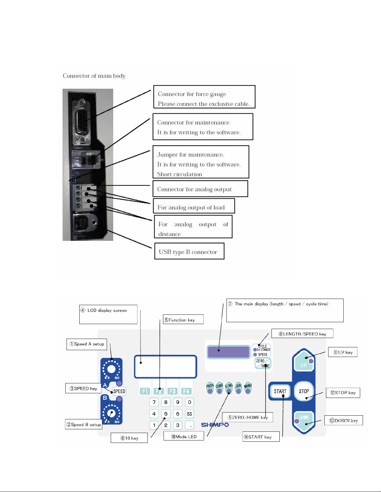
Description of Parts
There are two limit switches located on the side of the column. This limit
switches serves as mechanical stops for the force gauge bracket. This provides
a secondary safety stop in case of wrong entry on the program parameter.
To operate the limit switch, twist and push to slide in place.
Emergency Stop button located on the upper right section of the work table. This
is a master stop that will stop any movement and operation from the test stand.
It overrides all control functions from the test stand including software operation.
To reset simply turn counter clockwise and the button will release in place.
Page 3
.
Control Panel
Page 4

How to set up communication with the Test stand
1. Set the force gauge to 19200 Baud rate
2. Attach the force gauge to the mounting bracket
3. Attach the force gauge to the test stand using the FGS-FGV200P cable.
4. Important to follow the sequence of powering up the test stand
a. Turn on the Force gauge and allow initialization process
b. Turn on the force gauge, check if the model number of the attached
force gauge is reflected momentarily on the LCD.
c. Press Reset to reset to acknowledge the communication of the
force gauge.
Note: If the model number of the force gauge is not shown
a. Check the communication cable if it is firmly in place.
b. Verify if the force gauge is set to the right baud rate
c. Restart the power up procedure make sure that the force gauge is turned
on first before the test stand.
5. Choose the HOME position and press the ZERO/HOME button to accept
the new HOME position.
6. Using the function keys (F4) select the required MODE for testing. Each
time F4 or MOD button is pressed a corresponding LED indicator lights up
on the front display indicating the mode of the test stand. Pressing F4 or
MOD button after PROG, allows the user to go to the unit selection set
up. The following settings can be changed.
a. Distance – Millimeters or English units
b. Force – kg, lbs, N, oz, g (selection varies depending on the
attached force gauge).
Note: Pressing the F4 or MOD button after changes are made, scrolls
thru the available selection.
The Function keys changes selection depending on the window displayed.
Description of Different MODEs
1. MANU (Manual Mode) The simplest mode from the test stand. This
allows the user to reposition the force gauge bracket anywhere in the
column. Can be used for simple testing where one direction for test is
required.
Available Set up Options
a. Force limits can be entered to stop the test stand from moving.
Entering zero value disables the force limit function.
b. Speed is selected based from SPEED A or SPEED B. (Operation –
manual adjustments using the speed knobs).
Operation: The test stand moves based from the selected direction for test.
The test stand will continue to move towards the selected direction until
one of the conditions are met:
• One of the Limit switch has been activated
Page 5

• The STOP Button is pressed
• The set forece limit has been breached.
2. JOG (Jog Mode) Adjustment mode the test stand bracket will move based
on the activation of the UP and DOWN button. Unlike Manual Mode the
test stand bracket will stop as soon as the direction buttons are depressed
(momentary movement)
3. SING (Single Mode) Single operation for both direction. The test stand will
not only perform compression , but tension as well. The value for P1 and
P2 are based from which direction buttons is first pressed.
Available Set UP Options:
• Force Limits for both direction
• Dwell or hold time after the required distance or force had been
detected
• Tare function.
Operation: The test stand will perform one complete set of compression
and tenstion test.
Note: The test stand speed is manually adjsuted from the speed knobs
The test stand will move to the first selected direction then afterwards
move to the opposite direction.
4. CONT (Continuous Mode) this is similar to Single mode with multiple
cycles.
Available Options
• Force Limits for both direction
• Dwell or hold time after the required distance or force had been
detected
• Tare function.
• Speed can be entered using the key pads
Operation: The test stand will perform repeated sets of compression and
tenstion test. Ideal for fatigue testing.
5. PROG ( Program Mode) There are 3 program modes set to the test stand
a. TOP – Top Load Test
b. STD – Standard Test
c. BREAK – Break Test
TOP Load test is designed for bottle testing where a required amount of force
is needed within a particular displacement.
Under this mode there are five optional test points, which can be programmed
for down or up direction.
Page 6

NOTE: Entering a zero value for distance on any of the test points disable
that particular test point.
Available Set up Options:
• Threshold – this value is used to determine if the compression plate
made contact with test sample. It is recommended that a max
value of 0.2% of FS be used as the threshold value for testing.
• Cycles – number of repetition for test that requires more than one
test to be performed on a particular cycle. Max cycle from the test
stand can be set to as high as 9,999 times.
• AP (Approaching Point Distance) - Approaching distance from the
set HOME position. This function is very useful for testing samples
with different heights. Setting the value to “0” disables this function
and sets the threshold value as the main control for determining
where the test points starts (P1—P5).
• Force – force limits to prevent the force gauge bracket to move
forward or backwards once the set force has been detected.
• Direction – UP or Down direction for testing.
• Time – or Dwell time once the set distance has been reached.
STD or Standard Mode
This is the same as the regular test stand, allows users to have a preload value
to be set on the test stand to simulate real application conditions.
Similar to the TOP load test it has the same parameters and available options
with the absence of the threshold value which is replaced by PL or preload.
• Cycles – number of repetition for test that requires more than one test to
be performed on a particular cycle. Max cycle from the test stand can be
set to as high as 9,999 times.
• AP (Approaching Point Distance) - Approaching distance from the set
HOME position. This function is very useful for testing samples with
different heights. Setting the value to “0” disables this function and sets
the threshold value as the main control for determining where the test
points starts (P1—P5).
• Force – force limits to prevent the force gauge bracket to move forward or
backwards once the set force has been detected.
• Direction – UP or Down direction for testing.
• Time – or Dwell time once the set distance has been reached.
NOTE: In both test types if the value for distance is set to zero the program
ignores that test point.
Important to have the HOME position predetermined before entering parameter
settings.
Page 7
If the AP or Approaching distance is set wrong and the force gauge detects a
force prior to its completion. The test sand will terminate and end the program
and will stop.
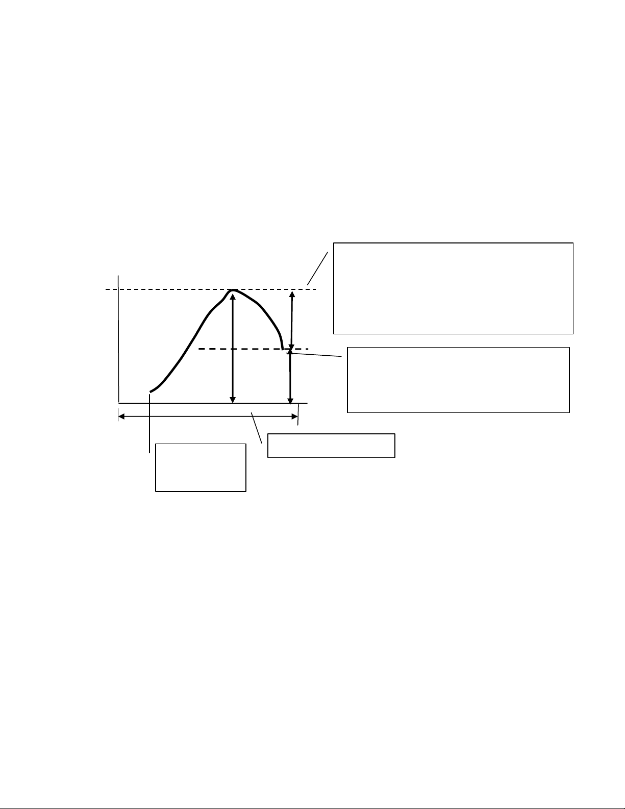
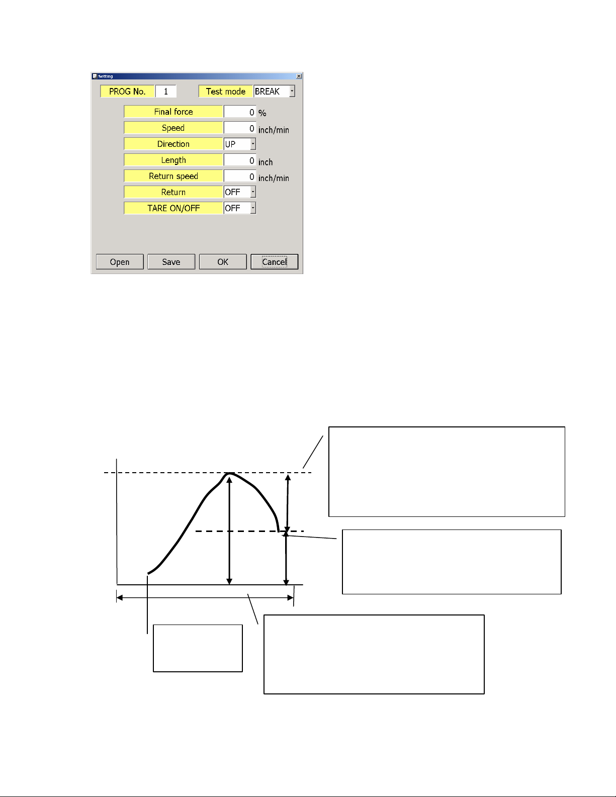
BREAK or Break Mode
The way the test stand determines the break point is to it detects the percent
drop from the Maximum peak value recorded.
MAXforce: 100g
Force
final_force is based on percentage of
MAXforce
Setting range : 0.5 – 100 %
MAXforce×final_force[%] = 100g x 10% = 10g
10g
100g – 10g = 90g, so after detect
90g
below 90g, test is finished. and
then, go back to start point
automatically.
100m
Tare ON/OFF
avairable.
From the diagram above the settings are as follows
Percent drop is set to 10 percent
Detected max value to be 100g
NOTE: Recommend not to set the percent drop less than 0.5%, this may trigger
false detection of the break point (Noise and vibration from the movement).
Distance
Operating Distance;
Page 8
Software for the FGS-200
System Requirements
• Minimum 512 RAM
• Windows 2000 (service pack 4) or Windows XP (service pack 2)
• 1 Gigabyte disk space
• USB 2.0 port
Materials
• FGS-FGV200P Communication Cable
• USB A to USB B Cable (6.6ft included in the test stand)
• Installation CD
Required programs:
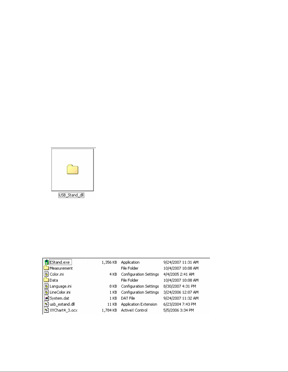
The installation CD should have the EStand_USB driver folder
Files in this folder
• Usb_estand.dll
• Usb_estand.inf
• Usb_estand.sys
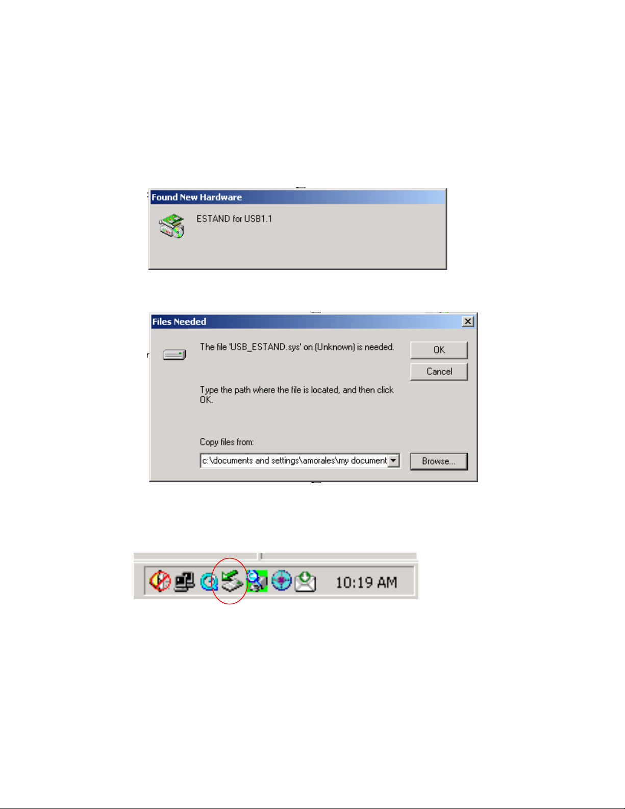
Program folder should contain the following files.
How to install the USB drivers?
Page 9
There are two ways to install the USB drivers.
• Go the USB_Stand_dll folder and right click on the USB_estand.inf file.
Select install from the options available.
• Depending on the Operating system, you may need to install the USB
driver particularly on the USB port that will be used.
a. Plug in the USB cable and allow the computer to detect the new
hardware.
This will appear on the window after the USB connection is detected.
Please select cancel on this window and look for the icon for the USB
device located on the bottom of the screen.
b. Double click on the Icon for the USB device
Page 10
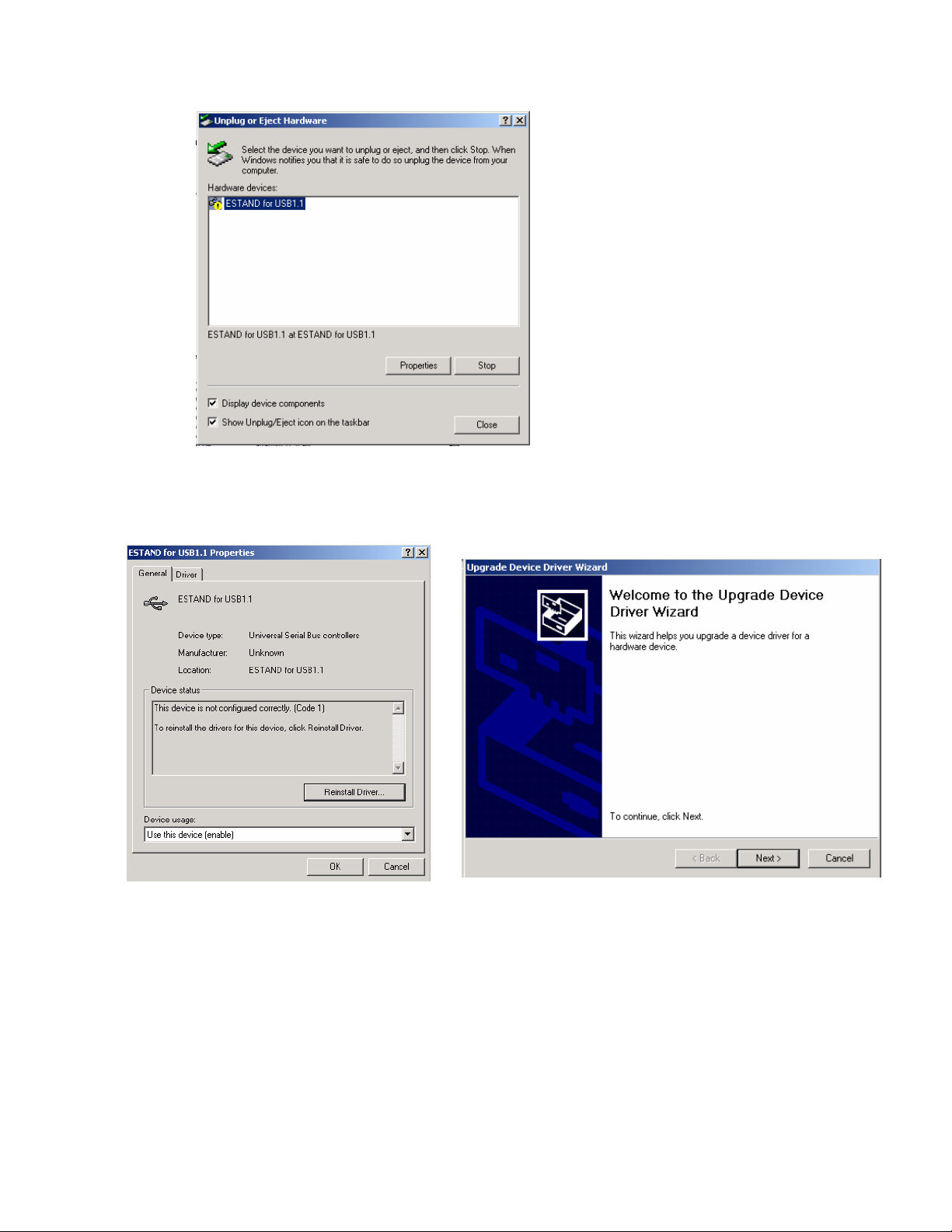
This window will appear on the screen. The yellow mark indicates that the USB
device is not recognized.
c. Select properties
d. Select Reinstall Driver, and follow the Driver Wizard
e. Select Next to proceed. From the location of the device driver
select specific location as the option as shown on the next page.
Page 11

f. Select Next and Have a disk button, browse to the location of the
USB driver folder
Page 12

g. Select the usb_estand.inf file then open. This will install the driver
to the particular port where the test stand is connected.
Browse the location of the USB_stand dll folder.
Page 13

Select finish to exit and complete the installation for the USB driver.
To test the communication, go back to the software folder.
(Make sure that the icon for the test stand is extracted together with
the other files on the zip. This will prevent OCX and runtime error from
occurring).
Open the folder and select EStand.exe icon to open the program
Page 14

The initial screen will appear within 5 seconds with the force gauge
type information.
If the program will not communicate an offline error will appear and the
force gauge information will not be reflected on the main screen.
• When this happens check the cable both the USB and the FGSFGV200P cable going towards the test stand.
• Sequence of powering up the devices are not correct. Turn off
the test stand and the force gauge.
o Turn on the force gauge
o Turn on the test stand
o Open the software
Note: If an OCX or runtime error appears, please check the Windows version
installed on the PC, this may need to be updated to service pack 4 for Windows
2000 and Service Pack 2 for Windows XP.
Description of the Software
Initial window
Initial Window holds information on the software version and controller version. It
also works as a test for proper communication from the test stand to the PC.
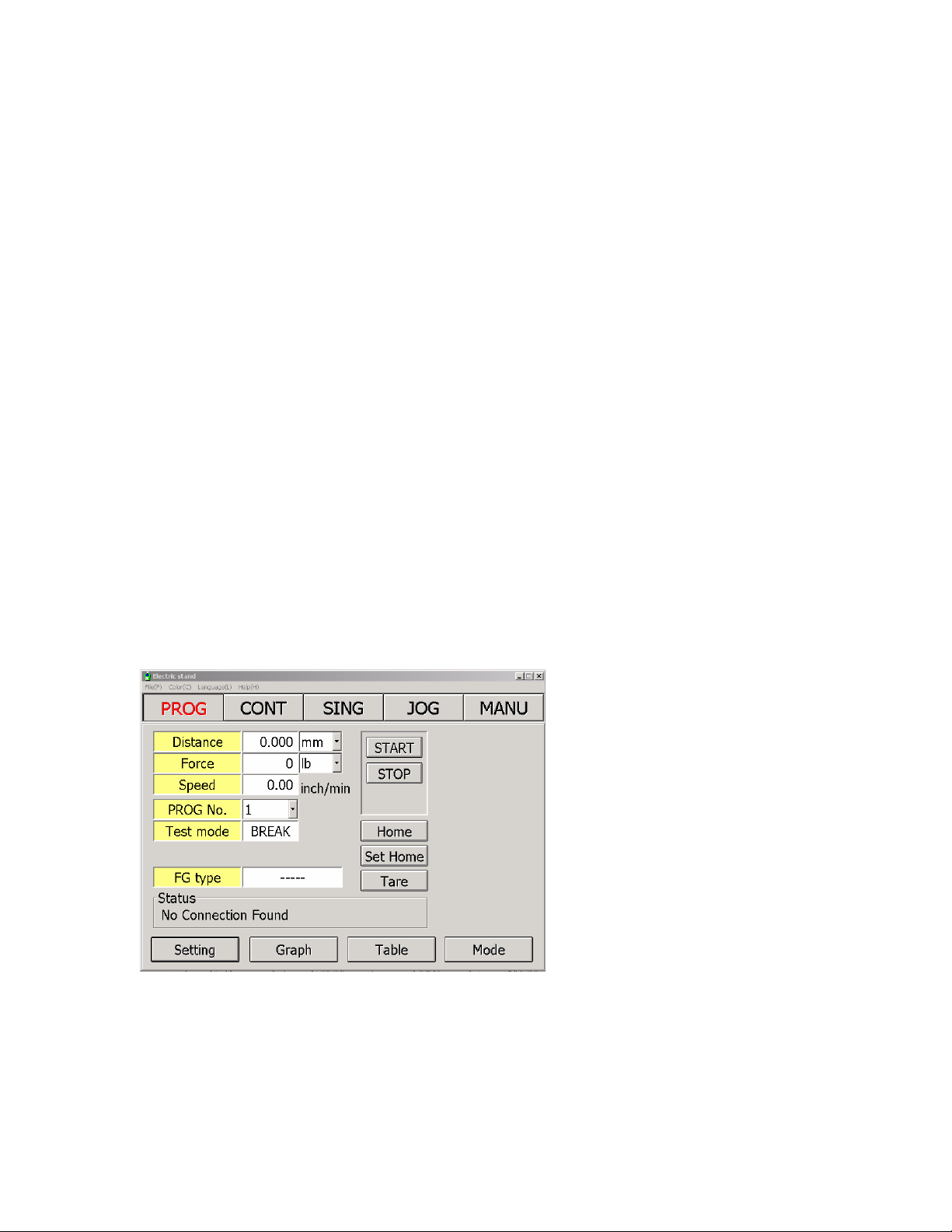
Main Window
The main window is a software replica of the test stand front panel.
It holds information pertaining to the condition and mode of the test stand.
Page 15

Modes
Available Menu on the Main Window
• File - exits out the program
• Color Scheme - changes the color of the window and its peripherals
• Language – this will be a future update to reflect different language on the
main window. Current version English only
• Modes buttons are located on top of the window, selected mode is
highlighted in red (Screen above indicates that the software is in
Continuous mode).
• Status indicator and Status message indicates condition of
the set up
• Start and Stop button are available (depending on mode
selected)
• Tare function for zeroing out the force gauge and
initializing the test
• Set Home button for changing the position of the reference
point or HOME position.
• HOME button for immediate return to reference point.
Page 16

Operating State
How to select the units for force and distance?
From the main window the units can be selected and changed. Force and
distance fields contain drop down windows for units of measure available. For
distance the fixed units are millimeters or Inches.
For Force, units vary depending on the model number of the force gauge. For
small force capacity (FGV-0.5X – FGV-2X) the available units are (Oz, g, lbs, N)
For models higher than 2 lbs (Kg, N, Lbs)
NOTE: Each the units are changed the previously saved data on the test
windows are erased. Only the existing values are converted to the selected
units.
Page 17
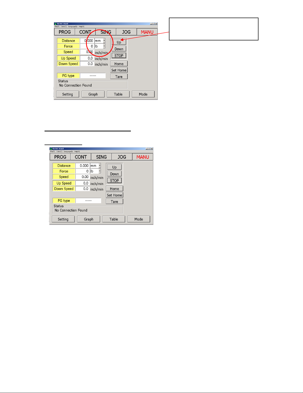
Drop down selection box for
force and speed
1
Description of Different Modes
Manual Mode
Speed can be adjusted from the main window. Enter value on the UP and Down
entry box.
Manual Mode or simple UP/ Down Test has the following settings
Page 18

• Tension Limit force – sets the maximum amount of force allowed for pull
or tension test. Values entered have units based from the selected units
of measure from the main Window.
• Compression Limit force – sets the maximum allowed compression or
push force.
Setting zero values on the tension and compression limit force disables this
function.
If the limits are reached the test stand will stop operation.
The UP and Down buttons allows the test stand to move in the selected direction.
It will continue to move until one or more of the following situation occurs.
• Limit Switch Activated (HI or Low).
• Stop condition is requested
• Set Limit force detected.
A warning message will appear if the entered value is set beyond what the
attached gauge can measure. Caution is required to prevent damaged on the
force gauge.
Page 19

The graph has an extension of the control features of the main window. Data
can be observe as the test progresses.
Comments can be entered to easily identify results.
Table Data
Separates the values based on the number of cycles.
• Table Type, has two formats point by point data or a summarize data
where max min and average values are reflected.
• Time Stamping is available on all graph window.
• A small summary table is also available for immediate review of each
cycle
• Table button sets the graph in a table format without the graph options.
• Clear button acts as a master reset for the mode. It erases all previously
saved data.
• Print prints the current screen for easy portability
• Save records the data set and the settings for the current test
• Load, loads previously saved data.
Graph Type: Allows the following graph types to be displayed on screen
• Force vs. Distance
• Force vs. Time
Page 20

Note all saved data on the table can be retrieved using Microsoft Excel (.csv file
extension.
Jog Mode
Jog mode or simply fine adjustment allows operation of test stand from the front
panel. The force gauge bracket moves depending on the length of time the UP or
down buttons are pressed from the test stand front panel.
Single Mode
This test performs one complete set for both compression and tension test.
Speeds for UP and Down Direction are entered from the main window.
NOTE: Point 1 and point 2 is determined based from, which direction is first
selected.
Force gauge bracket goes back to initial position after the test is completed.
Page 21

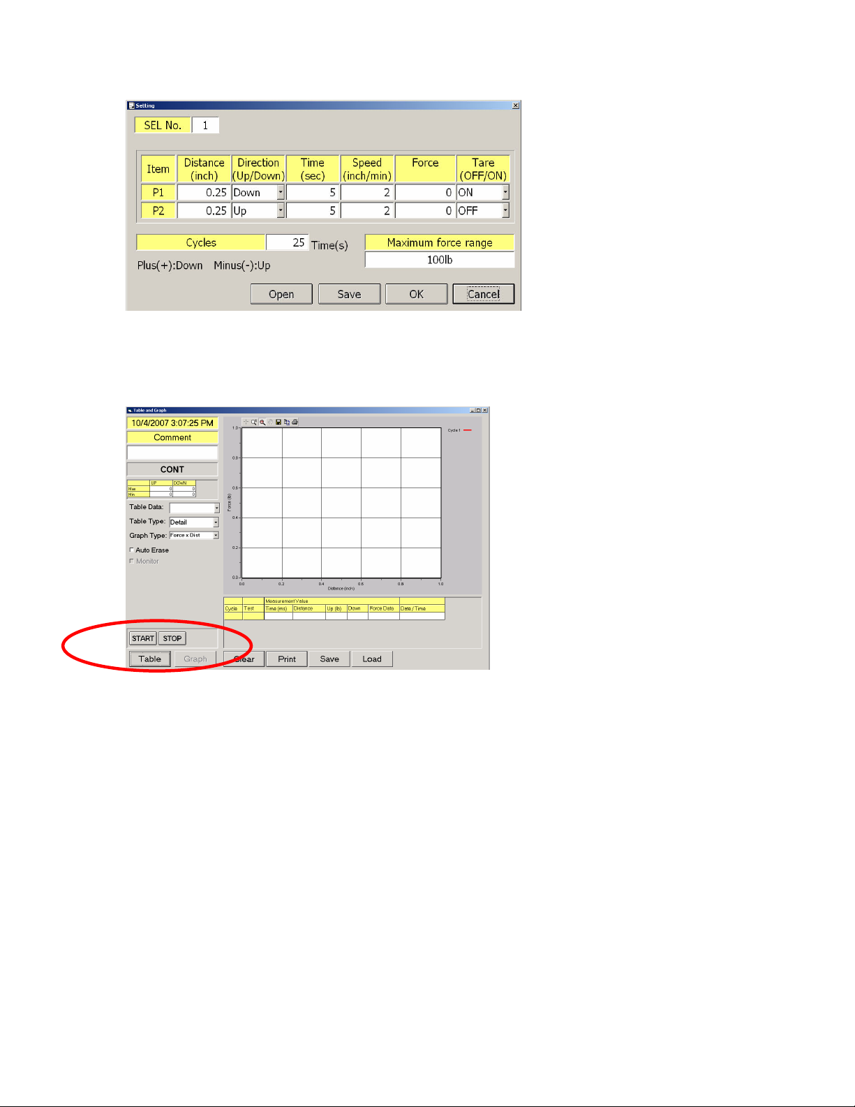
Settings window for single mode allows additional functions such as
Tare function both for P1 and P2,
P1 and P2 hold time or dwell time
Graphing function similar to Manual Mode, where the data are separated into
cycles
Continuous Mode
Continuous mode can be used for fatigue testing of small plastic materials
It allows distance to be entered for 2 points (P1 and P2).
Directions can also be defined based on the application.
Time can be set to hold the position after the set distance is reached.
In addition to this function cycles can be entered to perform multiple cycles on
one test. Limitation on the number of cycles is based from the availability of
computer resources (RAM and disk space).
Page 22

There are five available settings that can be stored in the program. Each one is
assigned by number.
This features allows easy access for comparing results by switching programs
back and forth Cuts down set up time where experimental results are
compared.
Note: The reference point has to be established correctly prior to using the
program selection. If each test set up has different home position, the settings
has to be adjusted to accommodate this change.
Page 23
P1 and P2 are determined based on the direction.
Standard function such as force limit which is Force in Continuous can be found.
Speed of the test is set from the setting window unlike the previous two programs
where the adjustments are entered on the main window.
Start and Stop replaced the UP and Down buttons from Manual and Single
Programs.
Note: The test stand is rated for 9999 cycles, but the PC software may perform
less depending on the availability of resources from the host PC.
Tare function should also be observed when activated on P2. The force gauge is
designed to shift zero when requested to tare values under load.
Example
The force gauge is showing a compressed reading of 5 lbs when a request of
tare is sent. The force gauge will show zero while on load (0.2% of FS) but after
the test is completed and it goes back to home the force gauge will indicate -5 to
compensate for the zero shifts.
Page 24

Recommend to tare the force gauge prior to the test to minimize additional forces
added on the data table.
A legend for each graph is set to identity force curves.
Limited to 24 colors, then the software recycles the color to be used.
Program Mode
Main feature of the test stand, it has 3 different types
STD-Standard
TOP – Top Load Test
BREAK – Break Test
TOP Mode
Indicates the existing setting on the program
Enable buttons
Page 25
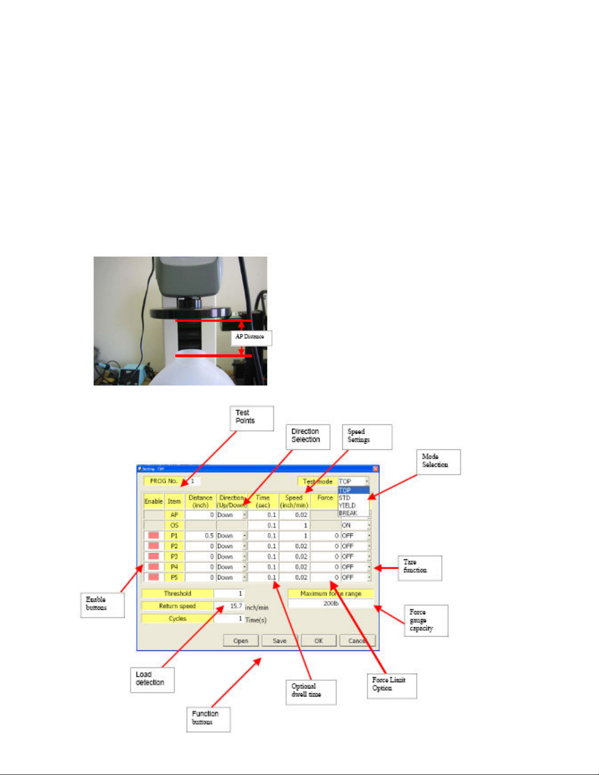
Test mode drop down window allows selection of test type
Enable buttons are also located on the setting window,
Red means enabled.
Threshold value can be entered which will determine the location of the top
portion of the test sample.
Note: if AP distance is set to wrong the program will terminate and exit out of the
program.
Zero values on distance will be ignored by the program even if there are time and
speed values entered.
Page 26

Standard Mode (STD)
STD or standard Testing works the same as a regular test stand with the addition
of the preload function.
The ideas is to have a preload value set to the test sample then start the test
from that initial condition.
Example springs with nominal force when attached to the end product being
tested for additional force
Non-Vibration rubber testing simulating conditions on a motor mount where initial
compression or shear force is present on actual application.
Cushion testing on the seals of a pneumatic cylinder.
The main window for Standard Mode is similar to TOP mode.
5 program settings can be stored on the program.
Page 27

Enable buttons
Standard mode is similar to TOP mode with the additional feature of allowing the
user to return to initial position after test and the preload function where force can
be entered to simulate actual conditions.
Pre-load setting
Return to Start point Option
Monitor function (available in program mode with 1 cycle)
Page 28
This function allows examination of results for long periods of time. It records
data and graph the max value on a particular date. This function helps in
quantifying the consistency of the end products.
Useful for auditing quality results over a period of time.
Note: If more than one test is performed in a day, it will only record the last
one and used that as the basis for the graph value.
Break Mode
Break mode is defined in the FGS-200 program as a percent drop from the
highest recorded max value on the test.
The percent drop can be adjusted based on the application and requirements of
the end user.
It is however advised to keep this value higher and with considerations on the
speed settings. Even though the test stand can detect the percent drop, if the
speed is higher the program may overshoot.
Values lower than 1% are prone to false activation due to possible vibration o
noise on the set up.
Break is designed for one cycle test, an optional continuance of the test if no
break is detected is possible by turning off the return position option.
Page 29
Break setting option include a length option
Priority of the test stand is Force, if no break or percent drop is detected on a
certain length the test stand stops or return to initial position.
Additional adjustments can then be made to increase the pull or decrease the
compression distance of the test sample.
Force
MAXforce: 100g
100m
Tare ON/OFF
avairable.
10g
90g
Distance
Operating Distance;
.
final_force is based on percentage of
MAXforce
Setting range : 0.5 – 100 %
MAXforce×final_force[%] = 100g x 10% = 10g
100g – 10g = 90g, so after detect
below 90g, test is finished. and
then, go back to start point
automatically.
Page 30

FGS-200PV
SPECIFICATIONS
Capacity 100 kgf (200 lbs.)
Reduction Ratio 1:20
Precision Ball Screw Pitch 4mm / 1 Rotation
Stroke 400 mm (15.7 inch)
Travel Speed 0.6 mm/min (0.02 inch/min) - 400 mm/min (15.7 inch/min)
Drive Systeem Servo Motor (Trapezoidal thread (pitch 4mm / 1 rotation)
Speed Setting Selectable Speed Knobs (Speed A and Speed B)
Display 5 digit LED
Cycle (max) 1 - 9,999 times
Analog Signal Output 5 mV/ mm max +/- 2 V (400 mm)
Emergency Switch Push/Twist and release emergency stop button
Operating Modes
MANU MANUAL - Operates to selectable force limits
JOG JOG - Operates while direction key is pressed
SING SINGLE - Operates one cycle between upper and lower force limits
CONT CONTINUOUS - Cycles test between upper and lower force limits.
PROG PROGRAM - Specific Program Tests (each can store 5 programs on each type)
TOP: Top Load test with threshold option
STD: Standard test with preload option
BREAK: Break point test with force drop detection
Communication Feature USB 1.1 communication from Test stand to PC
Force Gauge Compatibility FGV-X and DFS models (Made after 1991)
Communication Software Windows based program, virtual front panel compatible with Windows XP/2000
Alarm Overload protection for test stand motor (stops motor when overload condition occurs).
Work Space 200 mm (7.87 inch) X 280 mm (11.02 inch)
Operating Temperature 0 - 45 degrees Celcius (Non-condensing)
Power Supply 120 V AC
Weight 23 Kg
Page 31
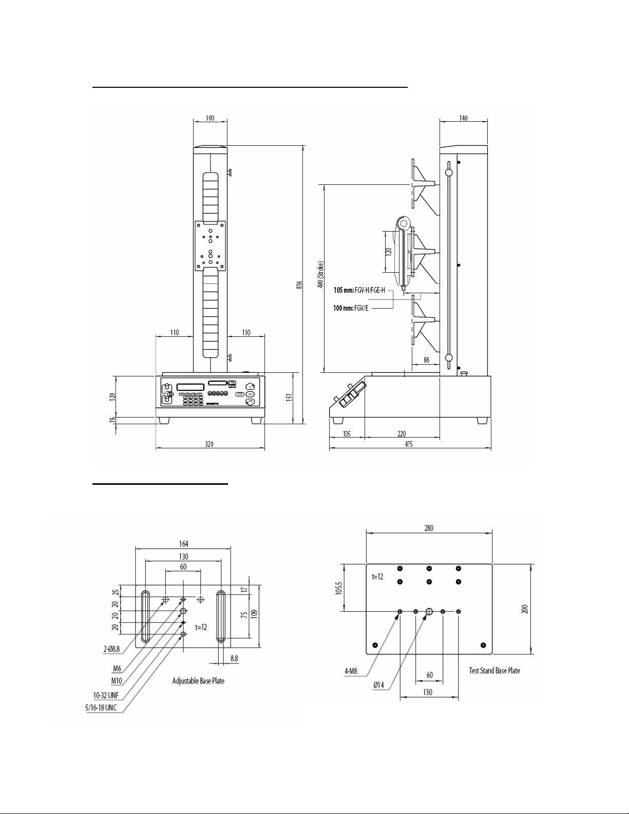
Drawings and Dimensions (All measurements in mm)
Base Plate Dimensions
 Loading...