

Page 1
DigitalDigital
Digital
DigitalDigital
Stroboscope/TStroboscope/T
Stroboscope/T
Stroboscope/TStroboscope/T
Model DTModel DT
Model DT
Model DTModel DT
-721-721
-721
-721-721
achometerachometer
achometer
achometerachometer
Operational Precautions
! Do not operate or store instrument in the following
places:
Explosive areas
Near water, oil, dust or chemicals
Areas where temperature is above 104°F (40°C).
! Do not look at the emitted light for long periods of
time; it can be harmful to the eyes.
! Do not disassemble or repair unit while in operation.
! To mount the strobe on a tripod (or any other
mounting surface), use screw 1/4 - 20unc, length
8mm or shorter , for the tripod screw hole on the bottom.
Instruction ManualInstruction Manual
Instruction Manual
Instruction ManualInstruction Manual
Features
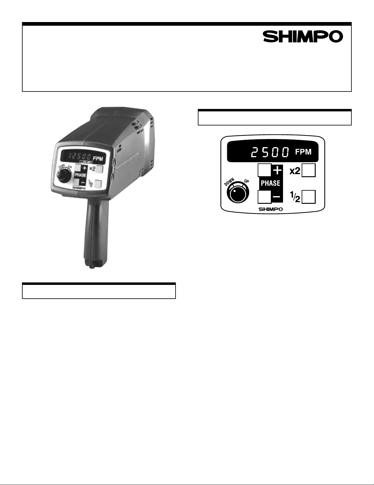
Setter
The setter changes the flashing rate. Turn CW to
increase the rate, turn CCW to decrease rate.
x2 Switch
Pressing "x2" will double and display the flashing rate.
1/2 Switch
Pressing the "1/2" will divide flashing rate by two and
display it.
Plus (+) Switch
When object appears to be standing still, pressing "+"
will give the illusion that the object is moving towards
the opposite direction of rotation. This action increases
the rate slightly (phase shift) and is used to place the
object in desired position.
Minus (–) Switch
When object appears to be standing still, pressing "–"
will give the illusion that the object is moving towards
the rotating direction. This action decreases the rate
slightly (phase shif) and is used for the same reason as
above.
Input and Output Connectors
Phonejack (3.5 mm)
Tip: Signal
Sleeve: GND
Power switch with lock option
Power cord
Page 2
Operation
Memory
Internal Triggering
1. Firmly plug power cord into a 100VAC (Japan), 120 VAC
(US) or 230 VAC (Europe) single phase.
2. Aim light beam at object under observation. The best
distance between the strobe and moving object is
approximately 2 ft.
3. Measure rpm by turning setter. Turn setter to adjust the
flashing rate to the rotational speed of the object. To
reach the desired rate faster, use the 1/2 or x2 switches.
External Triggering
1. Connect wires according to connector pin designation:
Tip: signal
Sleeve: Gnd
2. Plug power cord into a 100VAC (Japan), 120 VAC (US)
or 230 VAC (Europe). Pull power trigger switch and
lock it. When the ext. phone jack is inserted in unit, the
strobe automatically switches from the internal mode to
the external.
3. The strobe will flash every time the sensor puts out a
pulse. See specifications table for input signal require-
ments.
When the strobe is turned off and on again at a later time, it
will start to flash at the previous displayed rate regardless if
the setter has been moved or not.
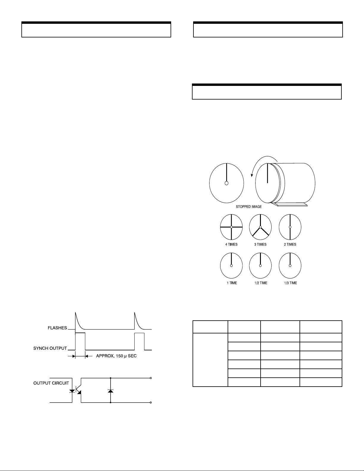
True RPM
All strobes give the illusion of stopped motion when flashing
in submultiples of the true speed.
To obtain the correct rpm, turn knob from highest fpm
downward. When the first single image appears, read the
true rpm. To verify it, press "1/2". A single image will appear
again.
4. If the input signal frequency exceeds upper or lower
limits, the alarm mark will be displayed and the strobe
will stop flashing.
Synchronous Output Signal
The Synchronous output signal appears on the tip of the
output phonejack.
See table for more information.
Rotation of shaft
(rpm)
at
1,500 rpm
Number of
flashes (rpm)
6,000 4 times 4
4,500 3 times 3
3,000 2 times 2
1,500 1 times 1
750 1/2 times 1
500 1/3 times 1
Flashes/
rpm shaft
Number of
stopped images
Page 3
Specifications
Flash Tube Replacement
MODELMODEL
MODEL
MODELMODEL
FLASHING RANGEFLASHING RANGE
FLASHING RANGE 40 — 12,500 FPM (Flashes Per Minute)
FLASHING RANGEFLASHING RANGE
ACCURACYACCURACY
ACCURACY ±0.02% of reading
ACCURACYACCURACY
RESOLRESOL
UTIONUTION
RESOL
UTION 0.1 , 40.0 – 4,999.9 FPM
RESOLRESOL
UTIONUTION
DISPLDISPL
AA
YY
DISPL
A
Y 5-Digit LED, 0.3" (8 mm) height
DISPLDISPL
AA
YY
RR
AA
TETE
R
A
TE Divide by 2, Multiply by 2
RR
AA
TETE
UPDAUPDA
TE TIMETE TIME
UPDA
TE TIME Ext. mode: varies with flashing rate
UPDAUPDA
TE TIMETE TIME
OPEROPER
AA
TING TIMETING TIME
OPER
A
TING TIME Continuous
OPEROPER
AA
TING TIMETING TIME
FLASH TUBE POWER/LIFEFLASH TUBE POWER/LIFE
FLASH TUBE POWER/LIFE Xenon, 10 W, 100 million flashes
FLASH TUBE POWER/LIFEFLASH TUBE POWER/LIFE
FLFL
ASH DURASH DUR
FL
ASH DUR
FLFL
ASH DURASH DUR
SIGNAL OUTPUTSIGNAL OUTPUT
SIGNAL OUTPUT NPN Open Collector (24 VDC max.,
SIGNAL OUTPUTSIGNAL OUTPUT
PHASE SHIFPHASE SHIF
PHASE SHIF
PHASE SHIFPHASE SHIF
EXTEXT
. TRIGGER. TRIGGER
EXT
. TRIGGER a) 12-24 VDC thru a 3-wire NPN output
EXTEXT
. TRIGGER. TRIGGER
INPUT SIGNALINPUT SIGNAL
INPUT SIGNAL b) 12 VDC thru a 2-wire proximity
INPUT SIGNALINPUT SIGNAL
POWER REQUIREMENTSPOWER REQUIREMENTS
POWER REQUIREMENTS 115 VAC ±10% 60/50 Hz
POWER REQUIREMENTSPOWER REQUIREMENTS
AA
TIONTION
A
TION 10 - 15 µs
AA
TIONTION
TT
T Internal mode only by using the “+”
TT
DTDT
- 721(AC)- 721(AC)
DT
- 721(AC)
DTDT
- 721(AC)- 721(AC)
0.2 , 5,000.0 – 7,999.8 FPM
0.5 , 8,000.0 – 9,999.5 FPM
1.0 , 10,000.0 – 12,500.0 FPM
50 mA) 150 µs typical
and “–” switches
sensor (requires external power supply)
sensor (leakage current 1 mA max.,
Load current 8 mA min.)
c) Switch or Relay contact
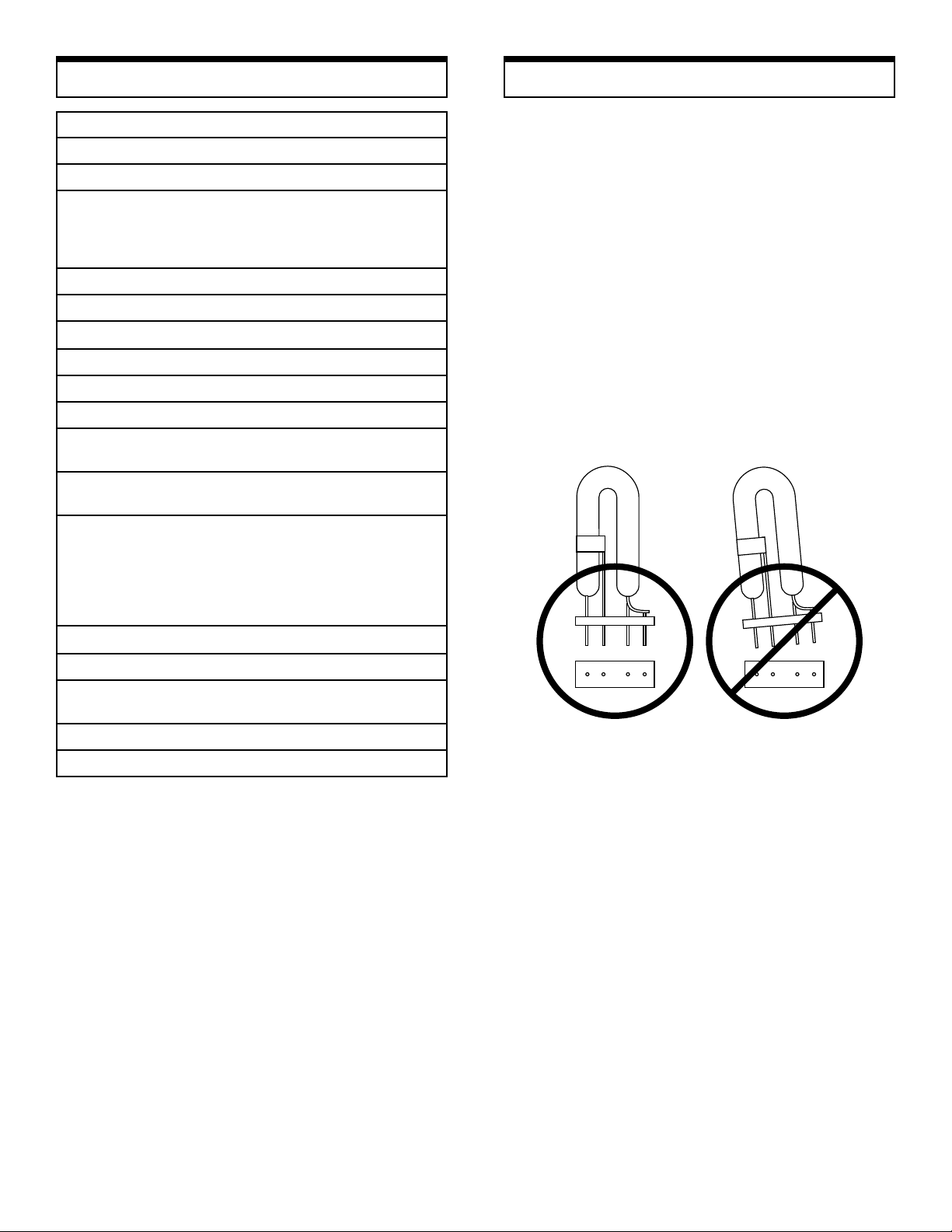
When FPM reading is displayed but unit is not flashing,
flash tube may need to be replaced.
1. Unplug line cord from power line. Turn power switch
OFF. Wait a few minutes until stroboscope is cool
before replacing flash tube.
2. Remove protective window by removing the 4 screws.
3. Use a rag and pull the tube out of its socket by rocking
it slightly up and down. Do not use bare hands to
remove tube, it may break and cause injury.
4. Insert new tube using the technique mentioned above.
Make sure that the tube is placed properly in the socket
otherwise it will touch the reflector. Tube should be set
symetrically within the neck of the reflector.
5. Replace protective window.
OPEROPER
AA
TING TEMPERTING TEMPER
OPER
A
TING TEMPER
OPEROPER
AA
TING TEMPERTING TEMPER
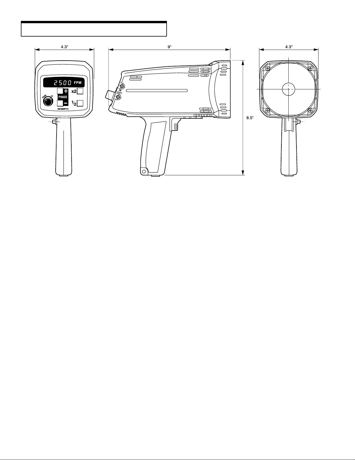
DIMENSIONSDIMENSIONS
DIMENSIONS 9" L x 4.3" W x 8.5" H
DIMENSIONSDIMENSIONS
WEIGHTWEIGHT
WEIGHT 1.5 lbs. (0.7 Kg)
WEIGHTWEIGHT
ACCESSORIES AVAILABLEACCESSORIES AVAILABLE
ACCESSORIES AVAILABLE Carr ying Case
ACCESSORIES AVAILABLEACCESSORIES AVAILABLE
AA
TURETURE
A
TURE 32° – 104° F (0 – 40° C)
AA
TURETURE
(Height includes handle)
Page 4
Dimensions (mm)
"""""""""""""""""""""""""""""""""""""""""""""""""""""
SHIMPO ONE-SHIMPO ONE-
SHIMPO ONE-
SHIMPO ONE-SHIMPO ONE-
LIMITED EXPRESS WARRANTY: Shimpo Instruments warrants, to the original pur-
chaser of new products only , that this product shall be free from defects in workmanship
and materials under normal use and proper maintenance for one year from the date of
original purchase. This warranty shall not be effective if theproduct has been subject to
overload, misuse, negligence, or accident, or if the product has been repaired or altered
outside of Shimpo Instruments’s authorized control in any respect which in Shimpo
Instruments’s judgment, adversely affects its condition or operation.
DISCLAIMER OF ALL OTHER WARRANTIES: The foregoing warranty constitutes
the SOLE AND EXCLUSIVE WARRANTY, and Shimpo Instruments hereby disclaims all
other warranties, expressed, statutory or implied, applicable to the product, including,
but not limited to all implied warranties of merchantability and fitness.
LIMITATION OF REMEDY: Under this warranty, Shimpo Instruments’s SOLE
OBLIGATION SHALL BE TO REPAIR OR REPLACE the defective product or part, at
Shimpo Instruments’s option. Shimpo Instruments reserves the right to satisfy warranty
"""""""""""""
YEAR WYEAR W
YEAR W
YEAR WYEAR W
ARRANTYARRANTY
ARRANTY
ARRANTYARRANTY
obligation in full by reimbursing Buyer for all payments made to Shimpo Instruments,
whereupon, title shall pass to Shimpo Instruments upon acceptance of return goods. T o
obtain warranty service, Purchaser must obtain Shimpo Instruments’s authorization before
returning the product, properly repackaged, freight pre-paid to Shimpo Instruments.
INDEMNIFICATION & LIMITATION OF DAMAGES: Buyer agrees to indemnify and
hold Shimpo Instruments harmless from and against all claims and damages imposed
upon or incurred arising, directly or indirectly, from Buyer’s failure to perform or satisfy
any of the terms described herein. In no event shall Shimpo Instruments be liable for
injuries of any nature involving the product, including incidental or consequential damages
to person or property, any economic loss or loss of use.
MERGER CLAUSE: Any statements made by the Seller’s representative do not constitute warranties except to the extent that they also appear in writing. This writing con-
stitutes the entire and final expression of the parties’ agreement.
"""""""""""""
"""""""""""""""""""""""""""""""""""""""""""""""""""""
 Loading...