

Page 1
PP
anel Mount Tanel Mount T
P
anel Mount T
PP
anel Mount Tanel Mount T
achometerachometer
achometer
achometerachometer
Model DTModel DT
Model DT
Model DTModel DT
FeaturesFeatures
Features
FeaturesFeatures
This microprocessor-controller digital tachometer can be
used in any direct rpm application where no special gears
or generators are required. Here are some of its outstanding features:
!
Mounts easily — no brackets or screws required.
!
Any AC line voltage between 85 and 264 (50/60 Hz)
can power the unit.
!
Parameters are easily set via front panel membrane
switches.
!
Parameter settings are stored in a nonvolatile
memory.
!
Pulses per revolution range is 1 - 9999.
!
Signal LED on front panel.
-5TP-5TP
-5TP
-5TP-5TP
Instruction ManualInstruction Manual
Instruction Manual
Instruction ManualInstruction Manual
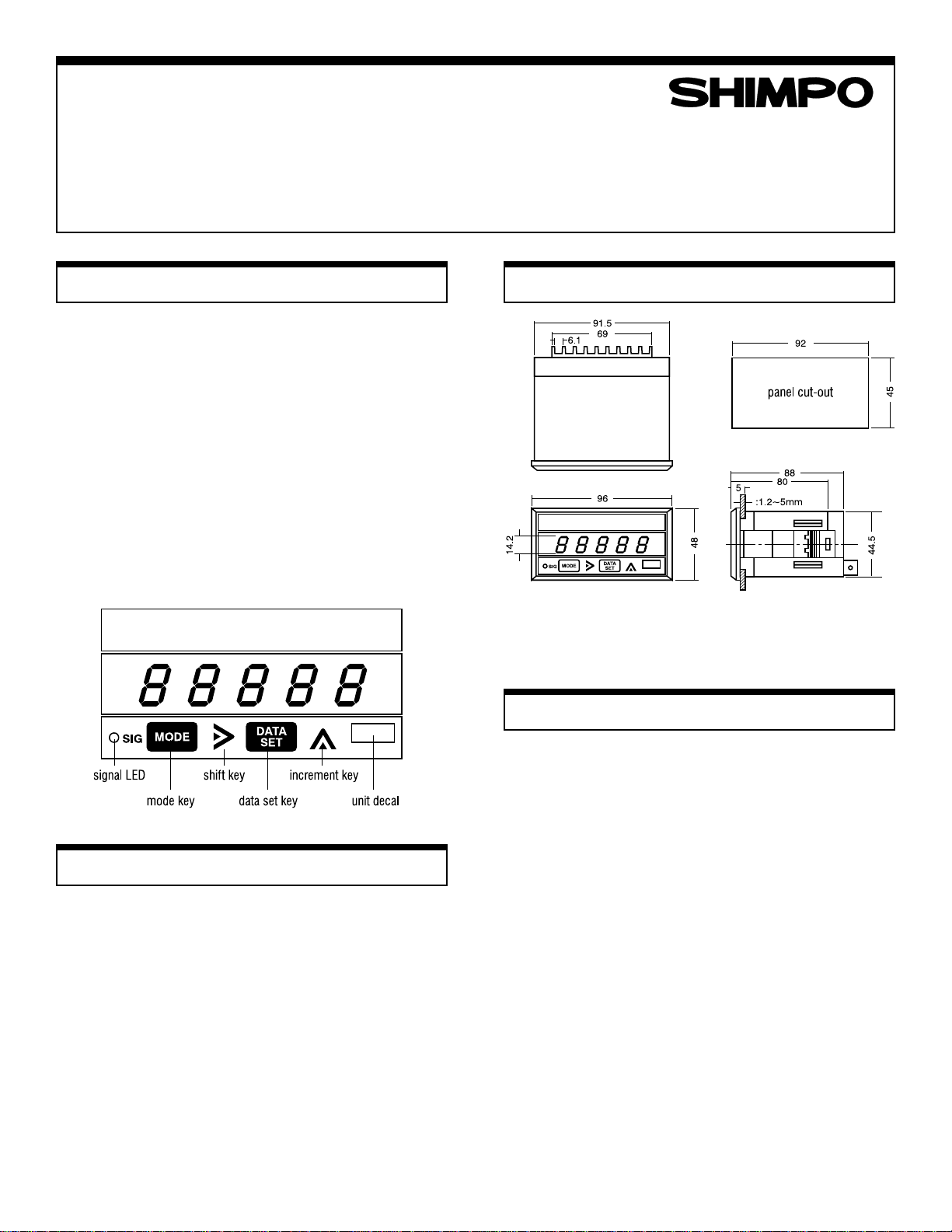
Dimensions (mm)Dimensions (mm)
Dimensions (mm)
Dimensions (mm)Dimensions (mm)
Operational POperational P
Operational P
Operational POperational P
!
If the unit is used in a caustic environment, we
suggest you use a NEMA 4X enclosure.
!
Keep unit free of vibration and shock.
!
When installing unit, keep power and sensor wires
separate. Tie cable shield to terminal E (earth ground).
!
After inserting wires, tighten terminal screws securely.
recautionsrecautions
recautions
recautionsrecautions
InstallationInstallation
Installation
InstallationInstallation
Our 1/8 DIN case design eliminates the need for brackets
and screws for installation. With the tachometer in a level
position, insert it into the panel cutout. Gently push the
face of the unit until the front bezel locks into place. If the
tachometer case is loose, adjust the integral bracket with
the enclosed tool.
Page 2
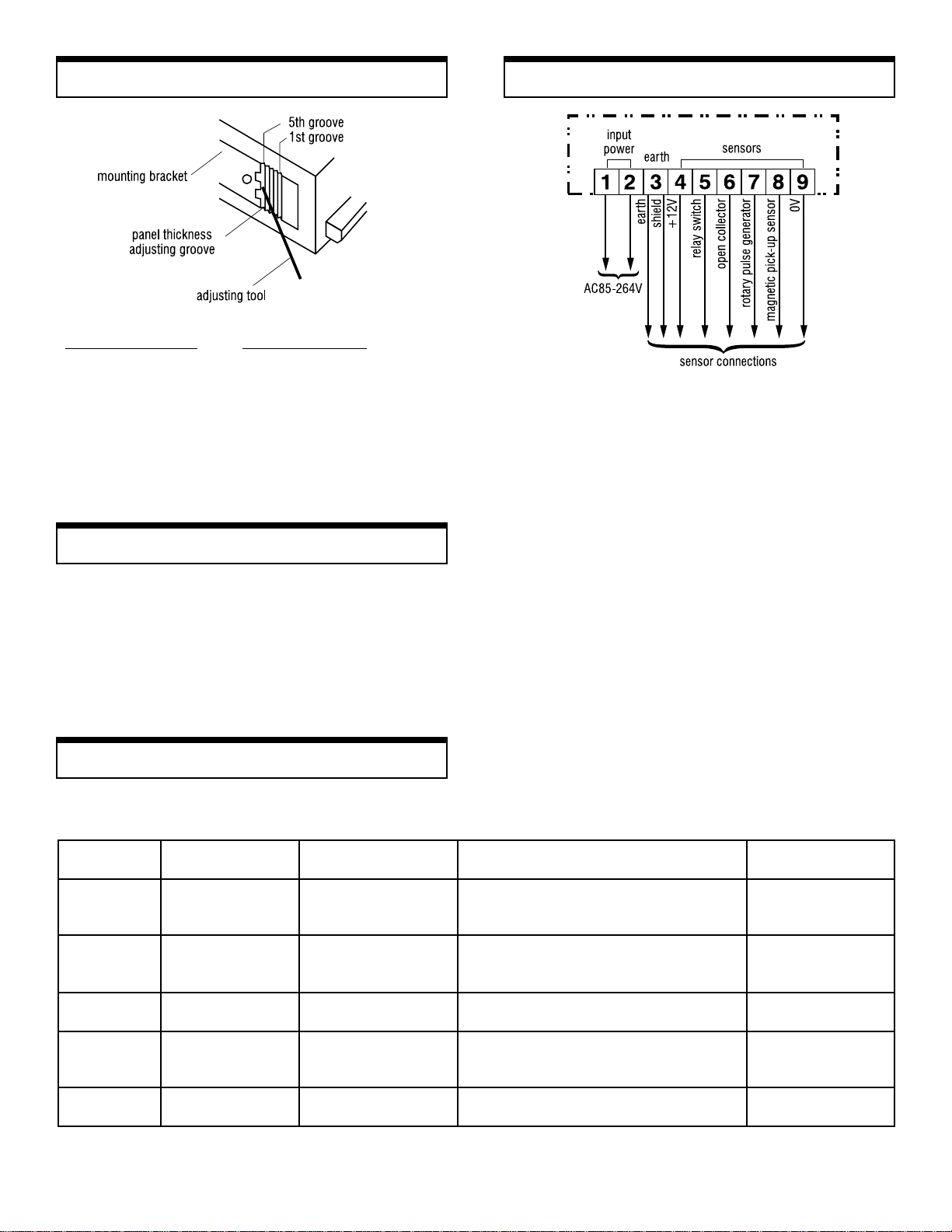
Mounting Bracket AMounting Bracket A
Mounting Bracket A
Mounting Bracket AMounting Bracket A
djustmentdjustment
djustment
djustmentdjustment
Panel Thickness
Thickness of Panel Adjusting Groove
1.2 – 1.6 mm 5th groove (factory setting)
1.8 – 2.5 mm 4th groove
2.8 – 3.6 mm 3rd groove
4.0 – 4.5 mm 2nd groove
5.0 mm 1st groove
RR
emoving Unitemoving Unit
R
emoving Unit
RR
emoving Unitemoving Unit
From the rear of the tachometer, alternately push the unit
from the left and right. This will free it for easy removal.
ConnectionsConnections
Connections
ConnectionsConnections
1&2 Line voltage input. AC voltage must be between 85
and 264 volts.
3 Earth ground. Connect all cable shielding to this
terminal.
4 12 VDC 50mA max. This sensor power supply is for
any sensor that requires external power
5 Switch closure input. To be used with a relay or
solenoid. The input frequency must be less than 20Hz.
6 For use with open collector sensors. Connect the
sensor's signal output wire. No need for an external
pull-up resistor.
7 Terminal to accept signals from rotary encoders or
pulse generators.
8 Standard input terminal for magnetic pick-ups and
proximity switches.
9 Signal ground or common.
SensorsSensors
Sensors
SensorsSensors
Shimpo offers a large selection of sensors to meet you application needs. The chart below shows
the optimum sensor to use when designing your system. Please call us for more information.
SENSOR FREQUENCY TYPE TERMINAL NUMBERS FREQUENCY OR RPM RANGE
RE1B–60C
RE1B–600C
RE1B–1000C
BI2–S12
DJ2–G
SE–G
RS220H
MCS–625
3030AN
MP–10
3070A*
Switch Closure Relay or Solenoid 5, 9, <20 Hz
* explosion proof
2
Rotary Pulse Generator
Proximity Switch
Proximity Switch
Proximity Gear Sensor
Retro Reflective Sensor
Magnetic Pick-up
3, 4, 7, 9,
3, 4, 7, 9,
3, 4, 7, 9,
4, 6, 9,
4, 8,
3, 4, 7, 9,
3, 4, 7, 9,
3, 4, 6, 9,
3, 8, 9,
3, 8, 9,
8, 9,
0–5000 rpm
0–3000 rpm
0–1800 rpm
0–2 KHz
0–1 KHZ
0–8KHz
0–500 Hz
0–250 Hz
Min. 5 I/s with 16 pitch gear .005" clearance
Min. 1 I/s with 12 pitch gear .005" clearance
OPERATION
TEMPERATURE
+14° F to +122° F
+14° F to +122° F
+14° F to +122° F
-13° F to +158° F
-4° F to +140° F
-4° F to +158° F
+14° F to +140° F
-22° F to +120° F
-100° F to +225° F
-40° F to +221° F
-100° F to +200° F
Page 3
Mode SelectionsMode Selections
Mode Selections
Mode SelectionsMode Selections
The DT-5TP operates in two modes. Mode 1 is programmed
when setting up rpm applications, and mode 5 is for
diagnostic testing:
Mode Function Application
1 Rate Direct r pm
measurement measurements
Setting PSetting P
Setting P
Setting PSetting P
PP
arameter 1: Pulses per Rarameter 1: Pulses per R
P
arameter 1: Pulses per R
PP
arameter 1: Pulses per Rarameter 1: Pulses per R
Sensing GearSensing Gear
Sensing Gear
Sensing GearSensing Gear
Here is how to change the parameter from 1 to 60 pulses
per revolution ("p/r"):
arametersarameters
arameters
arametersarameters
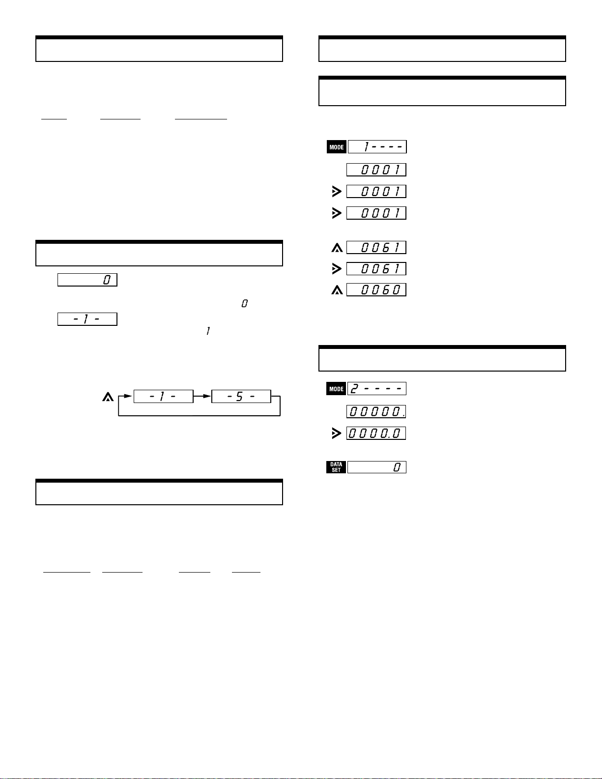
1.Set unit to mode 1.
evolution ofevolution of
evolution of
evolution ofevolution of
5 Self test Diagnostic test of LED
display and input
circuitry
Setting ModesSetting Modes
Setting Modes
Setting ModesSetting Modes
1.Apply any voltage between 85–264
VAC (50/60Hz) to terminals 1 and
2. The display will show
2.Press mode and data set keys for at
least 5 seconds.
3.Press the increment key to select
the desired mode. The display will
shift between mode 1 and mode 5.
4.Press mode key to activate mode 1
or mode 5.
will then appear.
(factory setting)
2.Press mode key.
3.Press shift key to select the
desired digit.
4.Press the increment key 6 times.
5.Press shift key.
6.Press the increment key 9 times.
.
Parameter 1 is now set for 60p/r.
PP
arameter 2: Decimal Parameter 2: Decimal P
P
arameter 2: Decimal P
PP
arameter 2: Decimal Parameter 2: Decimal P
1.Press mode key.
2.Press shift key to select position
of decimal point.
ointoint
oint
ointoint
Mode 1: RMode 1: R
Mode 1: R
Mode 1: RMode 1: R
The DT-5TP can directly measure any rotational rate
speed. The two parameters listed below may need to be
changed during system set-up.
Parameter Function Setting Range
1 Pulses per 1p/r 1–9999
2 Decimal point none 0–4th place
ate Measurementate Measurement
ate Measurement
ate Measurementate Measurement
Factory
revolution of
sensing system
Parameter settings are now complete.
Press data set key to begin counting.
3
Page 4

Mode 5: Self TMode 5: Self T
Mode 5: Self T
Mode 5: Self TMode 5: Self T
estest
est
estest
SpecificationsSpecifications
Specifications
SpecificationsSpecifications
This mode lets you check the LED display and input
circuitry.
1. After disconnecting sensor, press
mode and data set keys for five
seconds.
2.Press increment key until
display
shows mode 5.
3.Press mode key to test display
segments and decimal points.
4.Press mode key. The display will
show
will flash.
5. Press the data set key. The unit
is
now ready for counting.
and the signal
Model DT-5TP
Mode Rate Measurement
Display Range 0.0000–9.9999
0.000–99.999
0.00–999.99
0.0–9999.9
0–99999
Measuring range 10–99999 rpm (at 1p/r), 0.2–30000 rpm
Display period 1 sec. (1 p/r input 60 rpm or over)
Display Red LED (0.56" or 14.2 mm high)
Time base Controlled by a 4.194304 MHz crystal
Accuracy ±0.008% ± 1 digit
Measuring system CPU controlled
Input no. of p/r 1–9999 (programmable)
Input signal
characteristics
Input signal amplitude Sine wave (0.3–30 VP–P)
Input impedance Approx. 10 k ohms
Voltage output 12 VDC ±5% (50 mA max) to power sensors
Ambient temperature 32°–113° F (0°–45° C)
Power consumption 1W
Voltage requirements 85–264 VAC (50/60Hz)
Dimensions 3.46"L x 1.88"H x 3.78"W (88L x 48H x 96W
Weight 0.55 lbs (250g)
(at 60p/r)
1–6 sec. (1 p/r input 10–60 rpm)
Sine wave–max frequency 10 KHz
Square wave–max frequency 30 KHz
Open collector–max frequency 30 KHz
Contact closure–max frequency 20 Hz
Square wave LO: 0–1.5 V, HI 4–30 V
mm), includes bezel, fit 1/8 DIN cutout
Error CodesError Codes
Error Codes
Error CodesError Codes
Display Type of Error What to Do
EE-02 Internal memory Press data set key. Interrupt power at terminals 1 and 2.
EE-03 Memory recall 1. Press data set key.
2a. Press increment key. Display should show
2b. Press data set key. Display should show
2c. Press shift key. Display should show
2d. Press mode key. Display should show
and reset to . If display goes to or and
locks up, turn power off and on again and repeat above steps.
SHIMPO INSTRUMENTS 1701 Glenlake Avenue Itasca, IL 60143 USA (630) 924-7138 Fax (630) 924-0342
Page 5

PP
anel Mount Tanel Mount T
P
anel Mount T
PP
anel Mount Tanel Mount T
achometerachometer
achometer
achometerachometer
Model DTModel DT
Model DT
Model DTModel DT
FeaturesFeatures
Features
FeaturesFeatures
This microprocessor-controller digital tachometer can be
used in any direct rpm application where no special gears
or generators are required. Here are some of its outstanding features:
!
Mounts easily — no brackets or screws required.
!
Any DC line voltage between 9 and 35 VDC can
power the unit.
!
Parameters are easily set via front panel membrane
switches.
!
Parameter settings are stored in a nonvolatile
memory.
!
Pulses per revolution range is 1 - 9999.
!
Signal LED on front panel.
-5TP (VDC)-5TP (VDC)
-5TP (VDC)
-5TP (VDC)-5TP (VDC)
Instruction ManualInstruction Manual
Instruction Manual
Instruction ManualInstruction Manual
Dimensions (mm)Dimensions (mm)
Dimensions (mm)
Dimensions (mm)Dimensions (mm)
Operational POperational P
Operational P
Operational POperational P
!
If the unit is used in a caustic environment, we
suggest you use a NEMA 4X enclosure.
!
Keep unit free of vibration and shock.
!
When installing unit, keep power and sensor wires
separate. Tie cable shield to terminal E (earth ground).
!
After inserting wires, tighten terminal screws securely.
recautionsrecautions
recautions
recautionsrecautions
InstallationInstallation
Installation
InstallationInstallation
Our 1/8 DIN case design eliminates the need for brackets
and screws for installation. With the tachometer in a level
position, insert it into the panel cutout. Gently push the
face of the unit until the front bezel locks into place. If the
tachometer case is loose, adjust the integral bracket with
the enclosed tool.
Page 6

Mounting Bracket AMounting Bracket A
Mounting Bracket A
Mounting Bracket AMounting Bracket A
djustmentdjustment
djustment
djustmentdjustment
Panel Thickness
Thickness of Panel Adjusting Groove
1.2 – 1.6 mm 5th groove (factory setting)
1.8 – 2.5 mm 4th groove
2.8 – 3.6 mm 3rd groove
4.0 – 4.5 mm 2nd groove
5.0 mm 1st groove
RR
emoving Unitemoving Unit
R
emoving Unit
RR
emoving Unitemoving Unit
From the rear of the tachometer, alternately push the unit
from the left and right. This will free it for easy removal.
ConnectionsConnections
Connections
ConnectionsConnections
1&2 DC input terminals. Power required: 9–35 VDC, 1W.
3 Earth ground. Connect all cable shielding to this
terminal.
4 12 VDC 50mA max. This sensor power supply is for
any sensor that requires external power
5 Switch closure input. To be used with a relay or
solenoid. The input frequency must be less than 20Hz.
6 For use with open collector sensors. Connect the
sensor's signal output wire. No need for an external
pull-up resistor.
7 Terminal to accept signals from rotary encoders or
pulse generators.
8 Standard input terminal for magnetic pick-ups and
proximity switches.
9 Signal ground or common.
SensorsSensors
Sensors
SensorsSensors
Shimpo offers a large selection of sensors to meet you application needs. The chart below shows
the optimum sensor to use when designing your system. Please call us for more information.
ROSNESEPYTYCNEUQERFSREBMUNLANIMRETEGNARMPRROYCNEUQERF
C06B1ER
C006B1ER
C0001B1ER
21S2IB
G2JD
GES
H022SR
526SCM
NA0303
01PM
*A0703
hctiwS
erusolC
* explosion proof
2
esluPyratoR
rotareneG
hctiwSytimixorP
hctiwSytimixorP
raeGytimixorP
rosneS
evitcelfeRorteR
rosneS
pu-kciPcitengaM
dioneloSroyaleR,9,5zH02<
,9,7,4,3
,9,7,4,3
,9,7,4,3
,9,6,4
,8,4
,9,7,4,3
,9,7,4,3
,9,6,4,3
,9,8,3
,9,8,3
,9,8
mpr00050
mpr00030
mpr00810
zHK20
ZHK10
zHK80
zH0050
zH0520
NOITAREPO
ERUTAREPMET
F°221+otF°41+
F°221+otF°41+
F°221+otF°41+
F°851+otF°31F°041+otF°4F°851+otF°4-
F°041+otF°41+
F°021+otF°22-
ecnaraelc"500.raeghctip61htiws/I5.niM
ecnaraelc"500.raeghctip21htiws/I1.niM
F°522+otF°001-
F°122+otF°04-
F°002+otF°001-
Page 7

Mode SelectionsMode Selections
Mode Selections
Mode SelectionsMode Selections
The DT-5TP operates in two modes. Mode 1 is programmed
when setting up rpm applications, and mode 5 is for
diagnostic testing:
Mode Function Application
1 Rate Direct r pm
measurement measurements
Setting PSetting P
Setting P
Setting PSetting P
PP
arameter 1: Pulses per Rarameter 1: Pulses per R
P
arameter 1: Pulses per R
PP
arameter 1: Pulses per Rarameter 1: Pulses per R
Sensing GearSensing Gear
Sensing Gear
Sensing GearSensing Gear
Here is how to change the parameter from 1 to 60 pulses
per revolution ("p/r"):
arametersarameters
arameters
arametersarameters
1.Set unit to mode 1.
evolution ofevolution of
evolution of
evolution ofevolution of
5 Self test Diagnostic test of LED
display and input
circuitry
Setting ModesSetting Modes
Setting Modes
Setting ModesSetting Modes
1.Apply any voltage between 9–35
VDC to terminals 1 and 2.
The display will show
2.Press mode and data set keys for at
least 5 seconds.
3.Press the increment key to select
the desired mode. The display will
shift between mode 1 and mode 5.
4.Press mode key to activate mode 1
or mode 5.
.
will then appear.
(factory setting)
2.Press mode key.
3.Press shift key to select the
desired digit.
4.Press the increment key 6 times.
5.Press shift key.
6.Press the increment key 9 times.
Parameter 1 is now set for 60p/r.
PP
arameter 2: Decimal Parameter 2: Decimal P
P
arameter 2: Decimal P
PP
arameter 2: Decimal Parameter 2: Decimal P
1.Press mode key.
2.Press shift key to select position
of decimal point.
ointoint
oint
ointoint
Mode 1: RMode 1: R
Mode 1: R
Mode 1: RMode 1: R
The DT-5TP can directly measure any rotational rate
speed. The two parameters listed below may need to be
changed during system set-up.
Parameter Function Setting Range
1 Pulses per 1p/r 1–9999
2 Decimal point none 0–4th place
ate Measurementate Measurement
ate Measurement
ate Measurementate Measurement
Factory
revolution of
sensing system
Parameter settings are now complete.
Press data set key to begin counting.
3
Page 8

Mode 5: Self TMode 5: Self T
Mode 5: Self T
Mode 5: Self TMode 5: Self T
estest
est
estest
SpecificationsSpecifications
Specifications
SpecificationsSpecifications
This mode lets you check the LED display and input
circuitry.
1. After disconnecting sensor, press
mode and data set keys for five
seconds.
2.Press increment key until
display
shows mode 5.
3.Press mode key to test display
segments and decimal points.
4.Press mode key. The display will
show
will flash.
5. Press the data set key. The unit
is
now ready for counting.
and the signal
Model DT-5TP (VDC)
Mode Rate Measurement
Display Range 0.0000–9.9999
0.000–99.999
0.00–999.99
0.0–9999.9
0–99999
Measuring range 10–99999 rpm (at 1p/r), 0.2–30000 rpm
Display period 1 sec. (1 p/r input 60 rpm or over)
Display Red LED (0.56" or 14.2 mm high)
Time base Controlled by a 4.194304 MHz crystal
Accuracy ±0.008% ± 1 digit
Measuring system CPU controlled
Input no. of p/r 1–9999 (programmable)
Input signal
characteristics
Input signal amplitude Sine wave (0.3–30 VP–P)
Input impedance Approx. 10 k ohms
Voltage output 12 VDC ±5% (50 mA max) to power sensors
Ambient temperature 32°–113° F (0°–45° C)
Power consumption 1W
Voltage requirements 9–35 VDC
Dimensions 3.46"L x 1.88"H x 3.78"W (88L x 48H x 96W
Weight 0.55 lbs (250g)
(at 60p/r)
1–6 sec. (1 p/r input 10–60 rpm)
Sine wave–max frequency 10 KHz
Square wave–max frequency 30 KHz
Open collector–max frequency 30 KHz
Contact closure–max frequency 20 Hz
Square wave LO: 0–1.5 V, HI 4–30 V
mm), includes bezel, fit 1/8 DIN cutout
Error CodesError Codes
Error Codes
Error CodesError Codes
Display Type of Error What to Do
EE-02 Internal memory Press data set key. Interrupt power at terminals 1 and 2.
EE-03 Memory recall 1. Press data set key.
2a. Press increment key. Display should show
2b. Press data set key. Display should show
2c. Press shift key. Display should show
2d. Press mode key. Display should show
and reset to . If display goes to or and
locks up, turn power off and on again and repeat above steps.
SHIMPO INSTRUMENTS 1701 Glenlake Avenue Itasca, IL 60143 USA (630) 924-7138 Fax (630) 924-0342
 Loading...