

Page 1
Model DT-315P
DIGITAL STROBOSCOPE
INSTRUCTION MANUAL
Page 2
1. CAUTION
* Do not operate or store in the following places:
1. Explosive areas
2. Places where water, oil, chemicals, or dust, etc. exists
3. Places where the temperature is over 104°F (40°C)
* Avoid looking at the emitted light for long periods of time.
It may hurt your eyes.
* Do not attempt to dismantle or repair this unit.
* Use tripod screws 1/4-20unc, length 8mm or shorter for the tripod screw
holes on the bottom.
* Charge the battery before using the unit for the first time.
* After the power has been on for 10 minutes, the flashes will stop and the
display will flicker to protect the life of the xenon lamp. To continue
measuring, re-power on.
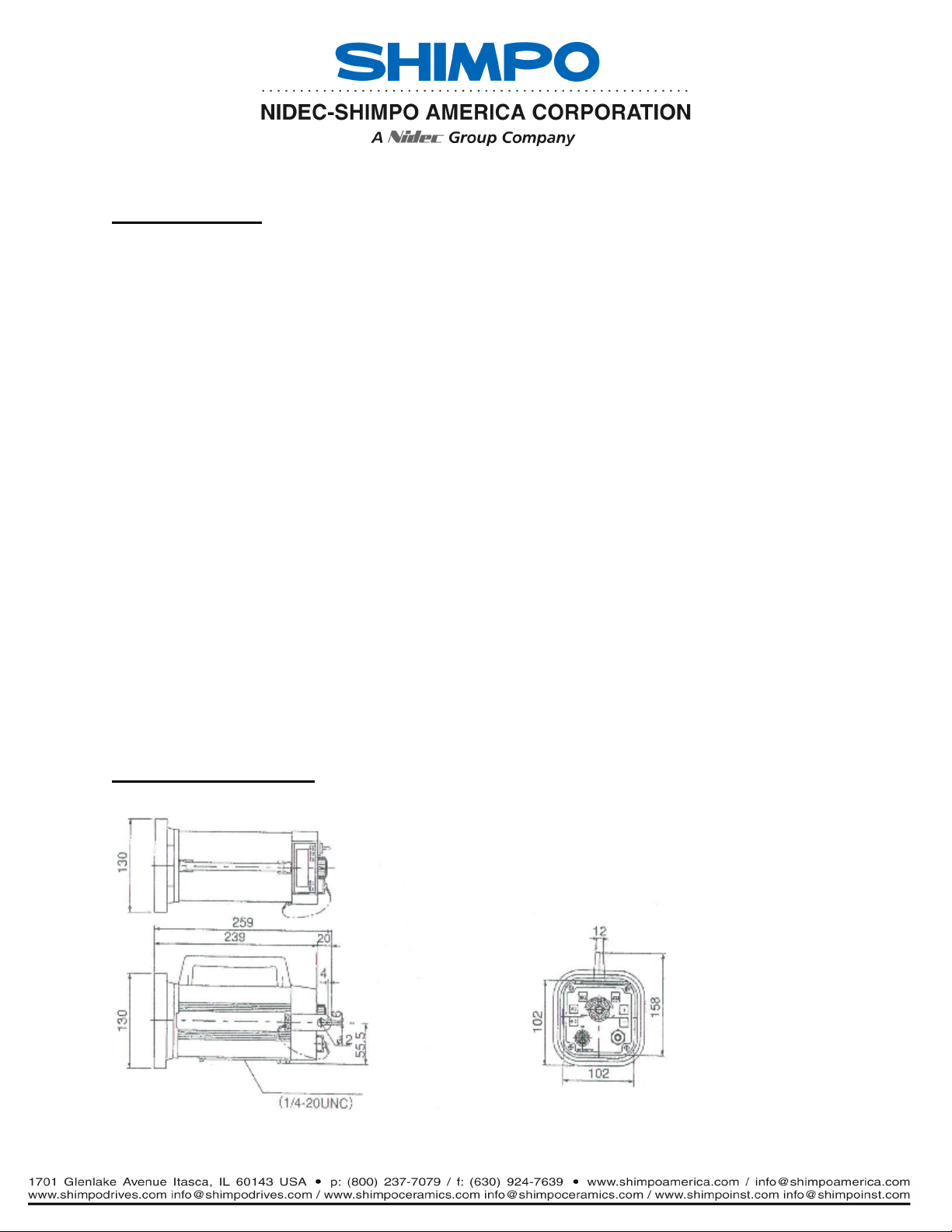
2. DIMENSIONS
Page 3
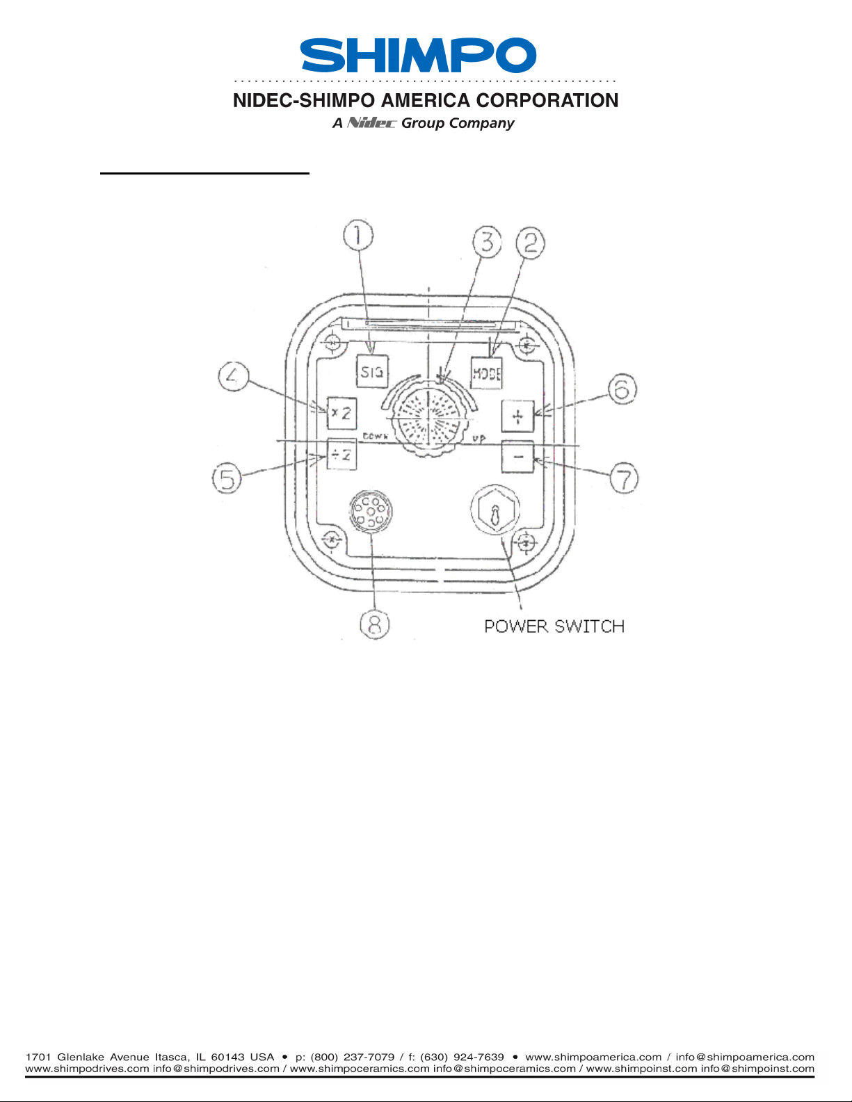
3. DESIGNATIONS
1. SIGNAL SWITCH
When the SIG button is depressed, the unit switches from the external
mode to the internal mode and vice-versa and the appropriate LED
lights.
2. MODE SWITCH
When the unit is switched to external mode, every time the mode
button is depressed, the strobe will move; rpm(fpm)-deg-m.sec.
rpm(fpm) ---- displays flashes per minute
External input: 100~3,000 FPM
deg ---- displays flash delay in degrees
m.sec ---- displays the flash delay in m.sec.
Page 4

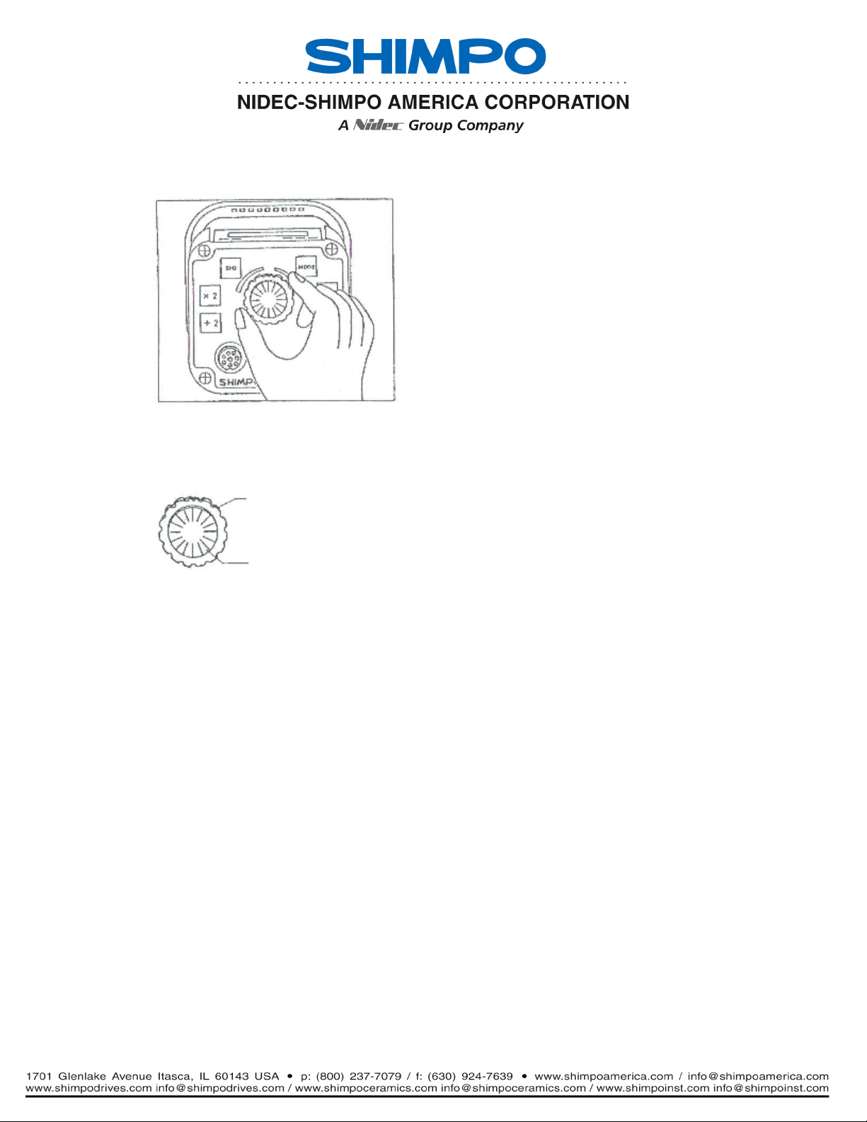
3. SETTER DIAL
The setter dial changes the flashing rate.
External dial ---- used for coarse adjustment:
clockwise for increasing rate.
counter-clockwise for decreasing rate.
The setter returns to mid-position.
Internal dial ---- used for fine tuning:
One turn of the dial will change 10 digits in the
display.
4. x2 SWITCH
In the internal mode, every time the x2 button is depressed, the
flashing rate is doubled.
5. ÷2 SWITCH
In the internal mode, every time the /2 button is depressed, the
flashing rate is decrease by half.
6. PLUS SHIFT SWITCH
When the object appears to be standing still, pressing this button will
give the illusion that the object is moving toward the rotating direction
at a speed of 1 rotation in 6 seconds.
7. MINUS SHIFT SWITCH
When the object appears to be standing still, pressing this button will
give the illusion that the object is moving in reverse of the rotating
direction at a speed of 1 rotation in 6 seconds.
Page 5

8. INPUT & OUTPUT CONNECTOR
PIN#1 +12V
PIN#2 Synchronized Output
PIN#3 Input Signal
PIN#4 0V
PIN#5 --PIN#6 +15V
PIN#7 0V
PIN#8 Earth Ground
4. OPERATION INTERNAL SIGNAL MODE
Interior signal mode INT
Mode can be changed alternatively by
SIG switch.
External signal mode EXT
Tune mode rpm display
Delay mode Deg display
Ms Conversion display
Mode can be changed in order by MODE
switch.
1. Firmly plug power cord into a 120VAC (USA) or 230VAC (Europe)
single phase outlet.
2. Turn power switch on.
3. Press the SIG button if the INT lamp does not light up.
4. Aim the light beam at the object under observation.
The best distance between the strobe and the moving object is
approximately 2 ft. (50 cm),
Page 6
5. Measuring rpm is done by turning the setter dial.
Turn the EXTERNAL KNOB to adjust the flashing rate to the
rotating speed of the object. The greater the turning
angle, the faster the flashing rate.
Turn the INTERNAL KNOB to adjust the flashing rate to
the rotating speed of the object precisely until the object
appears to be standing still.
When the frozen motion is obtained, press the x2 or ÷2 button:
When the x2 button is pressed, 2 frozen figures can be seen overlapped by
180 degree phase shift.
When the ÷2 button is pressed, a freed figure can be seen.
At this moment, the actual rpm of the rotating shaft can be displayed.
The phase shifted frozen motion can also be seen when the displayed rpm is
1/2, 1/3, 1/4, etc., of the rotating shaft. When the x2 or ÷2 buttons are
used effectively, the correct rpm can be attained.
When the + button is pressed, the frozen figure will shift towards the
rotating direction.
Page 7

4. OPERATION EXTERNAL SIGNAL MODE
Interior signal mode INT
Mode can be changed alternatively by
SIG switch.
External signal mode EXT
Tune mode rpm display
Delay mode Deg display
Ms Conversion display
Mode can be changed in order by MODE
switch.
1. Connect signal wires with main body of the instrument after soldering
the wires with connectors.
2. Firmly plug power cord into a 120VAC (USA) or 230VAC (Europe)
single phase outlet.
Page 8

4. Turn power switch on.
* Tune Mode RPM flashing
When receiving the input signal, the flashing will start and the input
signal will be converted and displayed in rpm. At this moment the
setter dial does not interfere.
* Delay Mode
When the input signal cycle is 360°, the flashing can be delayed by 1~359°.
The delayed angle is adjusted by the setter dial. The display unit can be
selected in deg. or ms.
deg flashing --- shows angle display
ms flashing --- shows time, converted from angle
Page 9

* In delay mode, the correct delayed angle can only be obtained with a stable
input signal.
If the input signal frequency exceeds the upper and lower limits, the alarm mark
will be displayed and the strobe will stop flashing.
IN RPM DISPLAY MODE
When the input signal exceeds 500Hz, the over mark will light.
When the input signal is lower than 1.6Hz, the under mark will light.
IN DEG, MSEC DISPLAY MODE
When the input signal exceeds 60Hz, the over mark will light.
When the input signal is lower than 3.3Hz, the under mark will light.
Page 10

SYNCHRONOUS SIGNAL OUTPUT
The synchronous signal is output from #2 pin connector.
MEMORY
All previous settings are stored in the memory. When the power is turned on
again, the strobe will revert back to the previous settings. If the memory data is
lost by over limit noise, press x2 and + buttons at the same time, then switch on
the power. This returns the strobe back to the factory settings.
Page 11

NOTE:
TRUE RPM
All strobes give the illusion of stopped motion when flashing submultiple of the
true speed.
* To obtain the correct rpm; Turn the dial from high rpm down to low rpm. When
the first single image appears, read the true rpm. To verify the rpm, press the
÷2 button. A single image will appear again.
FLASH TUBE REPLACEMENT
Indications:
• Lamp life is about 100 million flashes.
• Rotation speed is displayed, no flash is emitted.
• When the flash is intermittently emitted, this indicates the lamp must
be replaced.
• Only replace flash tube with the specified lamp: (FLASHTUBE311-2).
Directions:
(1) After unplugging the line cable from the power line, let the
stroboscope sit for about 30 minutes or longer. Be sure stroboscope is
cool to the touch before replacing the lamp.
(2) Remove the lamp protection window by loosening the 4 screws on the
window. Insert a fine screw driver into a hole of the protection window
and pull out.
Page 12

(3) Remove the reflector and pull out the lamp base. Caution, do not pull
out the lamp glass directly.
(4) Do not touch the flash tube with fingers. Use a clean cloth. Press the
lamp base to the socket in the proper direction to install the new
lamp.
(5) Important: In order to maintain protection against water, be sure to
mount the reflector in the center. Fix the reflector on the former
position and fix the protective window with fingers. Use a clean cloth.
Press the lamp base to the socket in the proper direction to install the
new lamp.
Page 13

* BATTERY CHARGER
1. Turn off the power. Plug the strobe into the SHIMPO provided AC
adapter/charger and charge the battery for approximately 10 hours.
The AC adapter/charger can be used to power the strobe for up to 10 hours,
then it must be disconnected in order to preserve battery life. The same is
true when charging the battery without the strobe flashing.
2. During operation, if the battery is fully discharged, the following message will
be displayed and the flashing will stop.
Page 14

Do not charge the battery in the following manner.
Do not use another brand of AC adapter.
Do not charge for over ten hours.
Do not charge the battery in a flammable material area.
BATTERY REPLACEMENT
The life of the built-in battery is 300 charges. If the recharging time shortens, the
battery is almost worn out. The battery must be replaced with a new one.
Page 15

CONTINUOUS OPERATION BT EXTERNAL POWER
* The strobe can be operated by using the provide AC adapter. Do not operate
the strobe over 10 hours to avoid overcharging the built-in battery.
If you operate the strobe with the AC adapter provided, remove the plug
connector from the built-in battery. Refer to the BATTERY REPLACEMENT
process.
* Operate by other power
If you operate the strobe by other power, remove the plug connector from the
built-in battery.
External power specifications
9~14.5VDC MAX 40mA
If the power is too high, the following message will be displayed.
Plug
Page 16

SPECIFICATIONS DT-315P
INTERNAL SIGNAL MODE
FLASHING RANGE 60.0~3,300FPM
DISPLAY ACCURACY ± 0.01%
DRIFT ± 0.01% (at 0 ~ 40°C)
UPDATE TIME (Approx.) 0.2 seconds
TONE OUTPUT SIGNAL
OTHER FUNCTIONS x1/2. x2 Flashings, Phase shift adjustment
EXTERNAL SIGNAL MODE
FLASHINGS In synchronous mode: 60~3,000FPM
In delay mode: 200~3,000FPM
DELAY ANGLE SETTING
RANGE (In delay mode) 0~359° Set by 1°
RPM in synchronous: e, 60~3,000FPM
DISPLAY
or 0~300mS conversion display
DISPLAY ACCURACY ± 0.01% plus ±1 digit in synchronous mode
+0 -0.2mS plus ±1 digit in delay mode
UPDATE TIME 1 second
H level 2.5~12V *50µS or over for H.L level
INPUT SIGNAL L level 0~0.4V *Trigger at rising edge
*Approx. 10KΩ impedance
Operate by built-in battery: 6.8~11.0V
SENSOR POWER Operate by adapter: 10.2~12.2V
Operate by DC: 9~14.5V: 7.8~14.1V
DELAY ANGLE in delay mode 0~359°
Page 17

SPECIFICATIONS
DISPLAY 5 digit, 7 segment red LED (Character height 0.39 in. (10mm)
SETTER FLASHING DELAY AGLE: JOG SHUTTLE
MODE, DISPLAY UNIT: TACT SWITCH
FLASHTUBE Xenon lamp: FLASHTUBE311-2
FLASHTUBE POWER MAX. 10W
FLASHTUBE TIME Approx. 0.30µSec
* Operation by built-in battery
Nicd battery, 8KR-2000sce SANYO
Operating time: approx. 1 hour (Full charge at 3,000 FPM)
Battery charge time: approx. 10 hours
Charge with the provided adapter.
Do not charge battery over 24 hours.
Operation during charging is possible.
When you are charging during use, do not
POWER use over 10 hours continuously
* Operate by external power
Unplug the connector of the built-in battery
before operating the strobe by external
power to avoid overcharging of the battery.
DC: 9~14.5V, Max 24W
(current consumption is 24W/input voltage)
or operate by provided adapter
AC: 100V ±10%, 50Hz, Max. 40VA
OPERATING TEMPERATURE 0-104°F (0-40°C)
WEIGHT Approx. 4.63 lbs (2.1kg)
POWER PLUG PJ-2 (Sato parts) or the equivalent
ACCESSORIES INPUT/OUTPUT SIGNAL PLUG, AC adapter
 Loading...