

Digital Force GaugeDigital Force Gauge
Digital Force Gauge
Digital Force GaugeDigital Force Gauge
Models DFS — 0.5, 1, 2, 5, 10, 20, 50, 100
DFS — 0.5R, 1R, 2R, 5R, 10R, 20R, 50R, 100R
ContentsContents
Contents
ContentsContents
Instruction ManualInstruction Manual
Instruction Manual
Instruction ManualInstruction Manual
Safety Precautions ....................................................2
Factory Settings ........................................................2
How to Change Units ...............................................3
How to Change Measuring Modes..........................3
Memory Modes......................................................... 4
Single (on-demand) Mode........................................4
Statistics.....................................................................4
Continuous Memory Mode......................................5
Standard Memory Mode .........................................5
Memory Back-up......................................................5
Comparator...............................................................5
How to Set Limits (HI/LO)......................................6
Parameter Setting.....................................................6
How to Select Parameters........................................7
Measuring Time & Peak Fast Mode.......................7
Setting Measuring Time & Peak Fast Mode..........8
Auto-Power-Off ........................................................8
Setting of Initial Conditions ....................................9
Output Selection .......................................................9
RS232C Output ......................................................10
Selecting Memory Mode ........................................ 11
Error Codes............................................................. 1 1
Low Battery Indication ..........................................11
External Control Input (TARE, HOLD) ..............12
External Input Selection ........................................13
Outputs(Analog, Comparator,
Digimatic, RS232C)........................................14, 15
Memory Data Output thru RS232C .....................16
Commands (External Control
Command thru RS232C).....................................17
Overload Output & Flow Control ........................18
Calibration ..............................................................19
Warranty .................................................................19
Specifications ..........................................................20
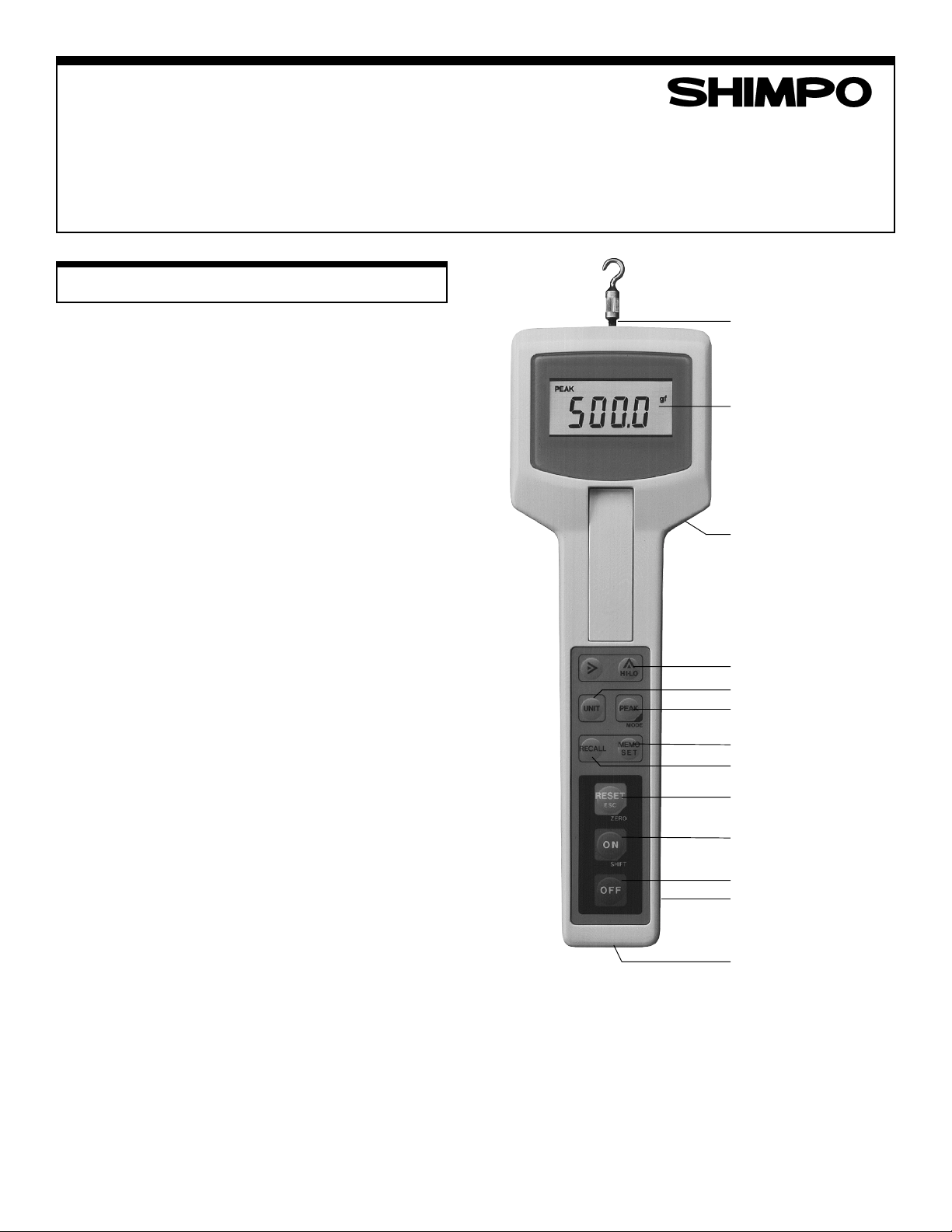
SHAFT
DISPLAY
AC ADAPTER
COMPARATOR
UNITS SELECTOR
PEAK MODE
MEMORY
MEMORY RECALL
RESET/TARE
POWER ON/SHIFT
POWER OFF
OVERLOAD OUTPUT
CONNECTOR
OUTPUT CONNECTER
1
Safety PSafety P
Safety P
Safety PSafety P
recautionsrecautions
recautions
recautionsrecautions
Factory SettingsFactory Settings
Factory Settings
Factory SettingsFactory Settings
1. Do not use any attachment that appears to be damaged.
2. Attachment must be properly installed. Hand tighten it.
Do not use wrenches or any other tools.
3. Do not exceed attachment capacity.
4. When installing gauge on a stand make sure to use all
necessary screws to secure unit.
5. Use eye protection devices when testing materials that
may shatter.
CautionCaution
Caution
CautionCaution
1. Do not use or store unit in extreme temperatures.
Note: Operating temperature is 0-45°C.
2. Do not use or store unit in oily, dusty or water splashing
areas.
3. If display shows stop test immediately and
release load. Over-load condition may damage the load
cell.
4. Do not apply force at an angle and avoid twisting the
shaft.
5. If gauge is not going to be used for a while, remove
batteries to avoid corrosion of battery terminals.
6. Use AC adapter that comes with the unit only. Any
other adapter will damage circuity.
7. Do not use any chemicals to clean outside case (including gasoline, alcohol e.t.c). Just use ordinary soapy
damp cloth.
8. Do not attempt to disassemble gauge. The warranty will
be voided.
Before UsingBefore Using
Before Using
Before UsingBefore Using
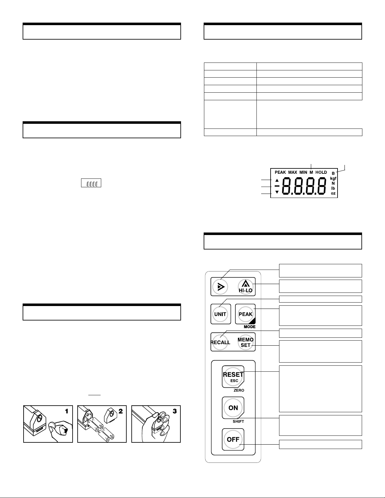
All DFS models come from the factory with the batteries not
installed. Before attempting to use the gauge install the four
AA batteries (provided) observing Figs. 1, 2 and 3 below.
Remove battery plate with a coin or appropriate screw driver.
Install 4-AA batteries as shown in Fig. 2 observing proper
polarity. Make sure lip engages properly before tighting the
battery plate screw.
Note: When the AC adapter is used, the batteries act as a
memory back up system only.
Each force Gauge comes from the factory with the settings
shown in the table 1 below
UNIT lb. or oz. (Depending on capacity)
MEASURING MODE Average
UPDATE TIME 0.125 seconds
AUTO POWER OFF 3 minutes
MEMORY MODE on demand mode (single data input)
OUTPUT RS232
INPUT Tare Function
Comparator indicator (over)
Comparator indicator (under)
Push Button FPush Button F
Push Button F
Push Button FPush Button F
(EIA)
Tension
Baud Rate:
Data Length:
Stop Bit:
Data End Code:
Software Flow Control:
Table 1
Memory Low battery
Fig. 1
unctionsunctions
unctions
unctionsunctions
Digit shift for comparator setting
Last Memory clear.
Comparator setting.
Comparator number check.
Unit
Measuring mode switch.
Statistics recall when in memory mode.
Shift + mode.
Memory recall
Memory store.
End key for for any setting.
Calibration.
Peak reset.
Prevent data entry.
Stop data output.
Prevent escape from
Memory recall.
Hold reset.
Tare (shift + zero)
4800 bps
8 bits
2 bits
None
Disabled
Power on
Shift key for
2nd function
Power off
2
RR
eady to Measureeady to Measure
R
eady to Measure
RR
eady to Measureeady to Measure
First press the ON switch to turn power ON. The display will
show momentarily all the indicators shown in Fig.1 and then
settle at lb (oz) and some arbitrary number with (usually but
not necessarily all zeros).
Assuming that the proper attachment is installed and the unit
is positioned as desired, press the ZERO and ON switches
simultaneously. The display should show all zeros, which
means that the gauge is “T ARED”.
How to Change UnitsHow to Change Units
How to Change Units
How to Change UnitsHow to Change Units
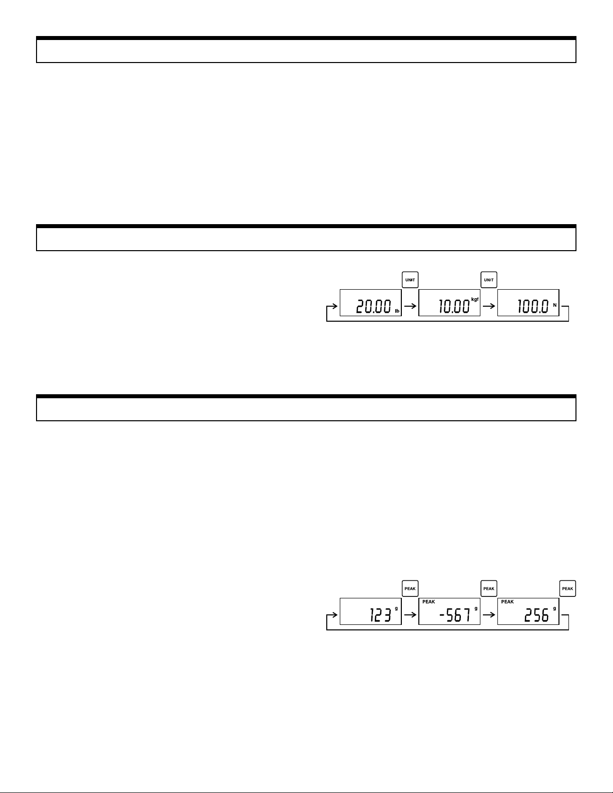
After the power is turned ON and gauge is “TARED”, by
pressing the UNIT switch the instrument will change from
lb(oz) to kg(g) to N and the cycle is repeated.
Caution: The gauge will default to lb (oz) (initial setting)
after power OFF regardless of what unit was previously
selected. To avoid above situation, see page 7.
The gauge is now ready to measure force according to the
factory settings shown in Table 1.
After measurements are finished, press the OFF switch to
turn unit off.
Note: The gauge will power off automatically in 3 minutes if
the OFF switch is not pressed. If the AC adapter is in use,
the AUTO-POWER-OFF function is inoperative.
Change of Measuring ModeChange of Measuring Mode
Change of Measuring Mode
Change of Measuring ModeChange of Measuring Mode
As was mentioned in previous pages the gauge is set from the
factory in the average mode. The sampling rates for the
average mode are 0.125, 0.25, 1 and 2 seconds (selectable).
In the PEAK mode if the sampling rate is set for 1/1000 sec.,
the actual peak force is captured. If another sampling rate is
chosen the maximum average force is captured. T o change
from average to peak mode press the PEAK switch once.
The display will show a negative sign in front of the digits.
This means that the gauge is ready to measure tension. If the
PEAK switch is pressed one more time the negative sign will
disappear and the gauge is ready to measure compression.
One more press of the PEAK switch will bring the unit back
to average mode.
The gauge is able to measure average, peak tension, and peak
compression in one operation. When in the average mode,
push on the shaft for a period of time and then pull the shaft
and release. When you press the PEAK switch the peak
tension appears on the display. One more push of the peak
switch and the display will show the peak compression. T o
cancel the peak value from the memory press the RESET
switch.
The gauge is set to go to the average mode when the power is
turned on. T o change this condition (go to peak on POWER
ON) see page 7.
3
Memory ModesMemory Modes
Memory Modes
Memory ModesMemory Modes
The memory of the DFS series operates in three distinct modes:
1. On-demand memory mode (single)
2. Continuous memory mode
3. Standard memory mode
ON-DEMAND MEMORY MODE (SINGLE)ON-DEMAND MEMORY MODE (SINGLE)
ON-DEMAND MEMORY MODE (SINGLE)
ON-DEMAND MEMORY MODE (SINGLE)ON-DEMAND MEMORY MODE (SINGLE)
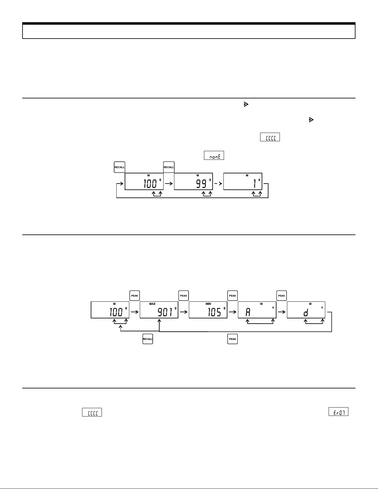
The unit comes from the factory set on the on-demand mode.
One hundred data can be stored in memory by pressing the
MEMO SET switch. If more than one hundred data are
forced into memory, the word FULL will appear on the
display. To recall the data in the memory press the RECALL
switch. The last data and memory position show up on the
display first. Any subsequent switch pressing will decrement
the data and memory position
By pressing the key, the last data in memory will be
erased. If unit is allowed to go OFF and then ON again, the
last data cannot be erased by pressing the key. To clear
the memory press RESET and ON switch at the same time.
The display will show momentarily and then go to
all zeros. If RECALL is pressed, the display will show
momentarily.
STST
AA
TISTICSTISTICS
ST
A
TISTICS
STST
AA
TISTICSTISTICS
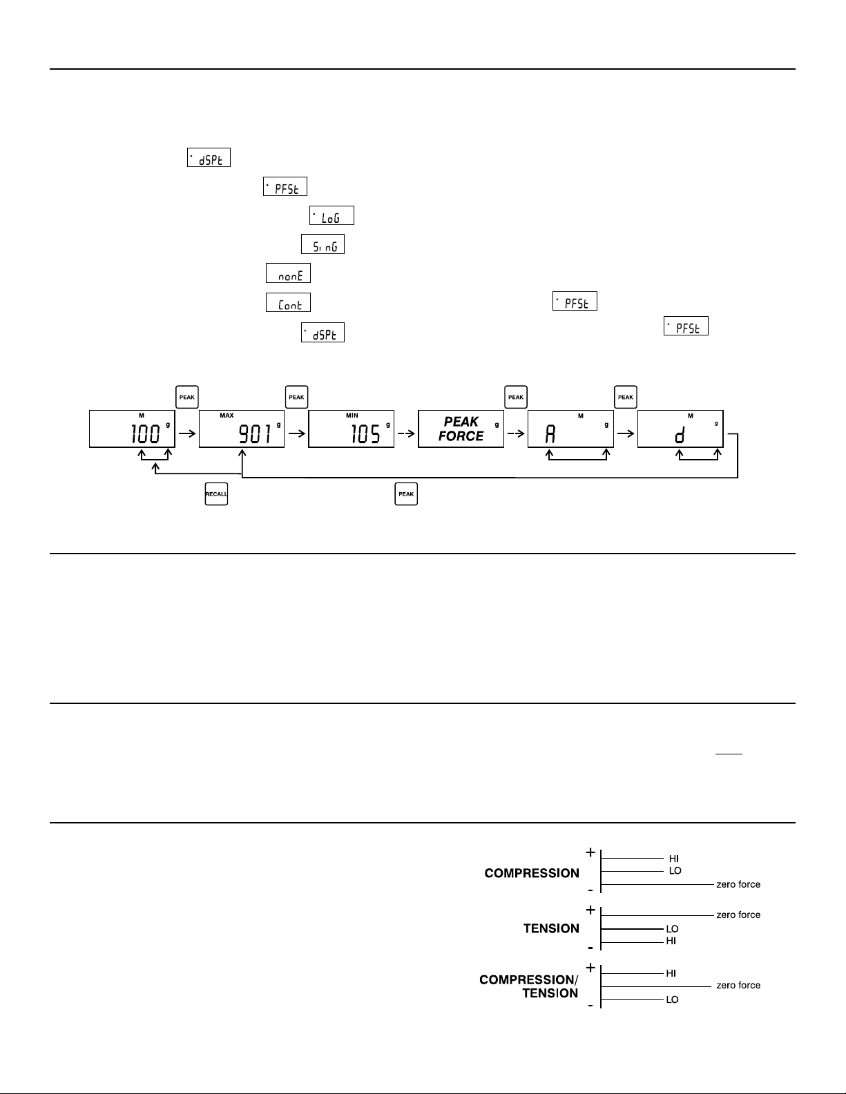
After the desired data has been stored in memory, set the
gauge in the RECALL mode and press the PEAK mode
switch. The last memory position will be displayed and also
the data in that position.
Subsequent manipulations of the peak switch will bring up
maximum, minimum, average data, and standard deviation.
See diagram below:
TO CLEAR MEMORYTO CLEAR MEMORY
TO CLEAR MEMORY
TO CLEAR MEMORYTO CLEAR MEMORY
T o clear memory from all data, press RECALL switch first
and then press simultaneously the ON and RESET switches.
The display will show momentarily and everything
will default to MEASURE (ready) state.
After standard deviation, by pressing peak again the unit goes
to maximum. T o escape from statistics press the RECALL
switch. T o escape from RECALL press the RESET(ESC)
switch.
Note: If the “UNIT” switch is pressed after a set of data has
entered the memory and new data is attempted to enter the
memory in different “units”, the display will show
which means that this action should be avoided. You cannot
change units during the process of entering data into memory.
4
CONTINUOUS MEMORY MODE CONTINUOUS MEMORY MODE
CONTINUOUS MEMORY MODE
CONTINUOUS MEMORY MODE CONTINUOUS MEMORY MODE
If the continuous memory mode must be used, do the
following to change from the ON-DEMAND mode to
continuous mode.
1. Press ON & PEAK at the same time.
Display will show .
2. Press PEAK. Display will show
3. Press PEAK 5 times. Display will show
4. Press MEMO SET . Display will show
5. Press PEAK. Display will show
6. Press PEAK. Display will show
You can enter 100 measurements at once in this mode.
While force is applied on the shaft, press MEMO SET.
The display will be changing according to force applied and
the letter M will be blinking on top of the numbers. When
100 measurements have entered the memory , the M letter
will disappear momentarily and the word FULL will appear
on the display momentarily and the letter M will reappear
solid. You can recall each measurement by pressing the
RECALL switch. T o clear the memory press RECALL, then
RESET and ON at the same time and the cycle can be
repeated.
Statistics can be performed in this mode as previously
described. If the is OFF, statistics can be performed
7. Press MEMO SET . Display will show
8. Press RESET . Now you are in the continuous memory
mode.
STST
ANDAND
ST
STST
Follow the same procedure as the one described above to
select the standard memory mode. The display will show
nonE. Proceed with steps 7 and 8 described above to stay in
the standard mode. In this mode the maximum and minimum
force (tension and compression) and last measurement are
MEMORY BACK UPMEMORY BACK UP
MEMORY BACK UP
MEMORY BACK UPMEMORY BACK UP
When power is off, memory back up is provided by the
batteries. If batteries are getting low, before a new set is
installed it is important to use the AC adapter and leave
ARD MEMORY MODEARD MEMORY MODE
AND
ARD MEMORY MODE
ANDAND
ARD MEMORY MODEARD MEMORY MODE
as described in previous pages. If the is ON, then the
PEAK force will show up between MIN and A (minimum
and average).
stored in memory in a selected period of time and can be
recalled later. If the selected period falls between a continuous compression and tension measurement, then the maximum compression and tension force will be stored and the
minimum will be zero for both.
power ON before removing old batteries otherwise data in
memory will be lost. When the AC adapter is used the
batteries are used as a memory back up system only.
COMPCOMP
COMP
COMPCOMP
T wo set points are available HI and LO.
Note: When the Digimatic output is selected, the comparator
output is not available. HI point is defined as follows:
HI < DATA (display)
OK or GO is defined as follows:
LO ≤ DATA ≤ HI
LO is defined as follows:
LO > DATA (display)
When setting the HI and LO limits, see adjacent diagrams.
ARAARA
ARA
ARAARA
TORTOR
TOR
TORTOR
5
How to Set LimitsHow to Set Limits
How to Set Limits
How to Set LimitsHow to Set Limits
Press to set upper limit. The arrow on the upper left corner
of the display will blink and the display will show previous
HI point (limit). Change setting by using the and
keys. After setting HI point, press MEMO SET to transfer
into memory. Unit is now ready to accept the lower point
(limit). Use the same procedure to accomplish LO point
setting. If it is attempted to set LO point higher than the HI
point the unit defaults to the beginning of the procedure.
When data exceeds these limits an arrow by the display
pointing upward or downward will indicate which limit is
PP
arameter Settingarameter Setting
P
arameter Setting
PP
arameter Settingarameter Setting
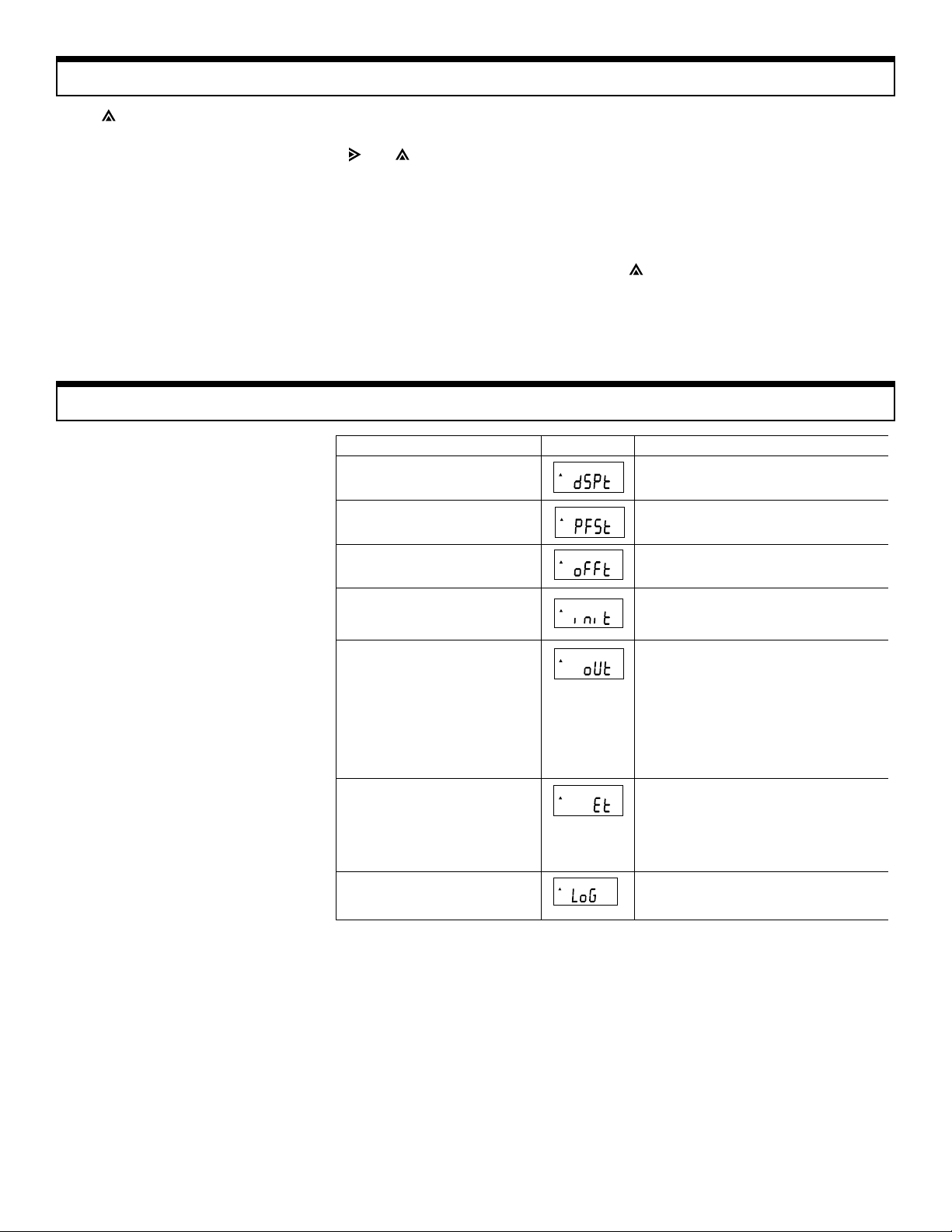
Many parameters can be set depending on operator’s requirements. See
typical parameters in the table below.
PARAMETER DESIGNATION
PARAMETER DESIGNATION DISPLAY
PARAMETER DESIGNATIONPARAMETER DESIGNATION
DISPLAY UPDATE (Measuring time)
DISPLAY UPDATE (Measuring time) 0.125, 0.25, 1, 2, sec. (select one)
DISPLAY UPDATE (Measuring time)DISPLAY UPDATE (Measuring time)
PEAK FAST MODE (1000 sample/sec)
PEAK FAST MODE (1000 sample/sec) ON, OFF (Select one)
PEAK FAST MODE (1000 sample/sec)PEAK FAST MODE (1000 sample/sec)
AUTO POWER OFF
AUTO POWER OFF NONE, 3 minutes (select one)
AUTO POWER OFFAUTO POWER OFF
exceeded. There are three OC NPN transistors that turn on
respectively if the corresponding set points are reached, HI,
GO and LO. These outputs can be used as alarms or indicators for the limits set. T o erase any or both of the set points,
just set them to zero. Erase HI point first.
Set the HI point to zero and press MEMO SET. Then set LO
point to zero and press MEMO SET . This is the only way
they can be erased from the memory. To check set points at
any time press the switch. The gauge comes from the
factory with both HI and LO points set to zero.
DISPLAY TYPICAL VALUE
DISPLAYDISPLAY
TYPICAL VALUE
TYPICAL VALUETYPICAL VALUE
INITIAL CONDITIONS
INITIAL CONDITIONS
INITIAL CONDITIONSINITIAL CONDITIONS
"Unit" when powered up.
"Unit" when powered up.
"Unit" when powered up."Unit" when powered up.
Measuring mode when powered up.
Measuring mode when powered up.
Measuring mode when powered up.Measuring mode when powered up.
OUTPUT
OUTPUT • None
OUTPUTOUTPUT
EXTERNAL
EXTERNAL
EXTERNALEXTERNAL
Control input
Control input
Control inputControl input
MEMORY MODE
MEMORY MODE • Single (on-demand)
MEMORY MODEMEMORY MODE
unit: kg(g), N, lb(oz)
display: average, peak tension, peak compression
• RS232C
Baud rate: 1200, 2400, 4800, 9600 (choose)
Data length: 7 or 8 bits
Stop pulse: 1 or 2 bits
Parity: none, even, odd
Data end code: CR, CR + LF
Software flow control: ON or OFF
• Digimatic
• None
• Tare
• Hold
Trigger: Edge, level
Trigger timing: contact close enable
contact open enable
• Continuous
• None (standard)
6

How THow T
How T
How THow T
1. Press ON and PEAK switches simultaneously . The gauge will display .
2. Press PEAK. The displaywill show . By pressing the PEAK switch the display will show the following sequence:
3. If you choose , press the MEMO SET switch. The action will get you in the memory field (single, none or continuous).
4. Press PEAK to display and choose any of the three modes.
o Select Po Select P
o Select P
o Select Po Select P
Note: If you press the RESET switch while you are in the memory field, the unit will default to step 2 .
arametersarameters
arameters
arametersarameters
5. Press MEMO SET to enter your selection, like → . After selection is made press RESET.
Measuring Time and PMeasuring Time and P
Measuring Time and P
Measuring Time and PMeasuring Time and P
Measuring time: Select one of the four time periods 0.125,
0.25, 1, or 2 seconds. When the peak fast mode is OFF, the
gauge will average the data for the selected period at the
1000/sec. rate. When the peak fast mode is ON, the gauge
will capture the maximum peak value from all data for the
selected time period at the 1000/sec. rate.
The table at right shows the
response time of the various
models. Due to mechanical
limitations the table shows
the 90% response time (see
graph 1).
MODEL
MODEL RESPONSE TIME
MODELMODEL
DFS-0.5, 1
DFS-0.5, 1 35 ms
DFS-0.5, 1DFS-0.5, 1
DFS-2
DFS-2 12 ms
DFS-2DFS-2
DFS-5, 10
DFS-5, 10 8 ms
DFS-5, 10DFS-5, 10
DFS-20, 50, 100
DFS-20, 50, 100 6 ms
DFS-20, 50, 100DFS-20, 50, 100
eak Fast Modeeak Fast Mode
eak Fast Mode
eak Fast Modeeak Fast Mode
Response times are shown with small attachments.
If heavier attachments are used the response time will be
slower.
RESPONSE TIME
RESPONSE TIMERESPONSE TIME
Graph 1
7

Setting Measuring Time and PSetting Measuring Time and P
Setting Measuring Time and P
Setting Measuring Time and PSetting Measuring Time and P
eak Fast Modeeak Fast Mode
eak Fast Mode
eak Fast Modeeak Fast Mode
See flow chart below. Press ON and PEAK switches simultaneously . The display will show dSPt
AA
uto - Puto - P
A
uto - P
AA
uto - Puto - P
ower - Offower - Off
ower - Off
ower - Offower - Off
Set measuring time and PEAK fast mode as the diagram
below indicates.
This option can be selected. If the auto-power-off option is
selected, the power will be turned off automatically after 3
minutes if no switches are activated during that time and if no
force change occurs during the 3 minute period. Force
change must be less than 0.1% of gauge’s capacity to be
defined as no change.
The auto-power-off will not work if
a) not selected
b) unit is in the continuous memory mode and data are
entering memory
c) AC adapter is in use
d) Unit is in calibration mode
Here is how to set up or cancel the auto-power-off option.
8

Setting of Initial ConditionsSetting of Initial Conditions
Setting of Initial Conditions
Setting of Initial ConditionsSetting of Initial Conditions
The gauge comes from the factory with the “unit” set in lbs
and the “measuring mode” in average. The “unit” condition
can be changed to N or Kgs by depressing the “unit” push
button. If a unit is selected other than lbs., when the power is
turned off and on again the gauge defaults back to initial
setting which is lbs.
The same holds true if the gauge is set at the auto-power-off
condition.
T o opt out of this condition follow the diagram below.
See page 7 to get to and follow diagram as shown.
Output SelectionOutput Selection
Output Selection
Output SelectionOutput Selection
The operator has the option in selecting:
a) RS232C
b) Digimatic
c) None
See page 7 and set the display on the
See flow chart below to select any of the outputs above.
9

RS232C outputRS232C output
RS232C output
RS232C outputRS232C output
If the RS232C output is selected, more parameters must be
chosen. See flow chart below:
When you have entered the RS232C output field and you
don’t want to change the factory settings, just press RESET
and you will exit this field.
10

Choosing Memory ModeChoosing Memory Mode
Choosing Memory Mode
Choosing Memory ModeChoosing Memory Mode
See page 7 to get to . Choose one of the memory
modes according to the diagram shown below:
Error CodesError Codes
Error Codes
Error CodesError Codes
If any of the error codes show up in the display,
turn power off and then on. If the error code
remains, see table below:
DISPLAY
DISPLAY CONDITION
DISPLAYDISPLAY
CONDITION ACTION
CONDITIONCONDITION
2
E PROM
reading error
Temperature
compensation error
Calibration error Unit needs repair and recalibration
D/A converter error Analog output will not tare. When tare is pressed
RS232C
communications error
Memory unit error This occurs if "units" are changed during
Overload condition or
load cell damaged
ACTION
ACTIONACTION
Press RESET.
Unit should go to factory settings
Bad temperature compensating ckt.
Send unit for repair. Unit may be used if
temperature is not a problem. Press RESET.
the voltage will not go to zero.
All else is OK. Repair is needed. Press RESET.
Check connections and all RS232C parameters
memory data entering. Some data in lbs, then
some in kgs, etc. Change units or clear memory
• Use proper load
• Repair unit by changing load cell
Low Battery IndicationLow Battery Indication
Low Battery Indication
Low Battery IndicationLow Battery Indication
When the letter B shows on the display , it means that the
batteries have to be changed. Note: Memory back up is
accomplished thru the batteries. Before changing batteries,
in order not to lose data in memory , plug in AC adapter and
turn gauge on.
11

External Control InputExternal Control Input
External Control Input
External Control InputExternal Control Input
TARE and data display HOLD can be externally controlled.
The Digimatic output shares the same wires as the external
control input. Make sure to use the RS232C output or no
Input: 5VDC, 0.3mA
Pulse width: >25ms
External TExternal T
External T
External TExternal T
To tare, short pins 5 and 10 for at least 25 ms.
External HOLDExternal HOLD
External HOLD
External HOLDExternal HOLD
AREARE
ARE
AREARE
output when the external control input function is used.
The external input cable looks like the one below:
} Comparator wires
Input (white)
gnd (BLACK)
Choose edge or level trigger and also OPEN or CLOSED
condition.
1. Level trigger: OPEN
Display holds present value when switch opens.
2. Level trigger: CLOSED
Display holds present value when switch closes.
3. Edge trigger: OPEN
Display holds present value after switch opens until it is reset.
4. Edge trigger: CLOSED
Display holds present value after switch closes unitl it is reset.
HOLD cannot be released from an external source in the
edge trigger mode. To release it press RESET. Level mode
can be released externally .
12

External Input SelectionExternal Input Selection
External Input Selection
External Input SelectionExternal Input Selection
From page 7 go to
When in HOLD mode, select trigger mode as follows:
13

OutputOutput
Output
OutputOutput
There are four outputs available:
1. RS232C
2. Digimatic
3. Analog
4. Comparator
Connector
I. Analog OutputI. Analog Output
I. Analog Output
I. Analog OutputI. Analog Output
The analog output is not derived from the CPU but is
generated from the load cell and amplifier. It is very linear
and has a high response time. When in TARE mode, the
analog output goes to zero volts.
Specifications
Voltage: -1VDC ~ 0 ~ +1VDC
Load Impedance: 2K or higher
Response Time: 35mS (DFS-0.5/1)
12mS (DFS-2)
8mS (DFS-5/10)
6mS (DFS-20/50/100)
1. RXD
2. TXD
3. CTS
4.
RTS
5. REQ
6. READY
7. CLK
8. DATA
9. (0±1V), Always present
10. GND
Digimatic*
RS232 (selectable)
5. Ext. Input
6. HI
7. GO
8. LO
Ext. Input*
Comparator
Output*
*Digimatic, External input and
Comparator output share wires.
Comparator OutputComparator Output
Comparator Output
Comparator OutputComparator Output
The comparator output shares wires with Digimatic and
External input, therefore when Digimatic is selected, the
comparator output is not available.
6
0C output
28 VDC, 7mA (max)
14
HI (yellow)
GO (green)
LO (red)
GND (black or blue)
TRIGGER INPUT (white or brown)
Comparator cable

Digimatic OutputDigimatic Output
Digimatic Output
Digimatic OutputDigimatic Output
Connect cable between gauge and Mitutoyo Model
DP-1HS printer. Select Digimatic output according
to previous instructions described on page 9. Press
RECALL to display DATA in memory . Then press
MEMO key . All data in memory will be outputed into
the printer. During the transfer of DATA from unit to
printer the doUt word on the display will be blinking.
When all data have been transferred, the unit returns
to measuring mode and the display stops blinking.
If the printer DATA key is pressed, only one measurement at
a time is transferred into the printer. STATISTICS from the
gauge will not be outputed because the printer has its own
capability of performing all the statistical functions.
RS232 CommunicationsRS232 Communications
RS232 Communications
RS232 CommunicationsRS232 Communications
All communications between the gauge and the PC are
possible with only one exception, the PC cannot turn the
gauge ON and OFF.
2 RXD
3 TXD
4 CTS
5 RTS*
7 GND
*RTS is always a "space"
(+5 to +10VDC)
BAUD RATE
BAUD RATE 1200, 2400, 4800, 9600
BAUD RATEBAUD RATE
DATA
DATA 8 bits
DATADATA
STOP BITS
STOP BITS 1, 2
STOP BITSSTOP BITS
PARITY
PARITY none, even, odd
PARITYPARITY
DATA END CODE
DATA END CODE CR, CR + LF
DATA END CODEDATA END CODE
SOFTWARE FLOW CONTROL
SOFTWARE FLOW CONTROL (X ON, XOFF)
SOFTWARE FLOW CONTROLSOFTWARE FLOW CONTROL
HARDWARE FLOW CONTROL
HARDWARE FLOW CONTROL CTS (clear to send signal)
HARDWARE FLOW CONTROLHARDWARE FLOW CONTROL
15

Memory DMemory D
Memory D
Memory DMemory D
AA
TT
A output thru RS232CA output thru RS232C
A
T
A output thru RS232C
AA
TT
A output thru RS232CA output thru RS232C
Data can be transferred from the memory in all three
modes. Press RECALL to display memory DATA
and then press MEMO SET
ON-DEMAND CONTINUOUS STANDARD
ST ATISTICS ST ATISTICS Units lbs
Max 98.8
Units lb Units lb Max - 0.0
DATA 100 DATA 100 MIN
MAX MAX MIN
MIN MIN LAST
AVG. PKC **END**
DEV PKT
HLMT AVG
LLMT DEV
HLMT
LLMT
DATA
1 XXXX
2 XXXX DATA
3 XXXX 1 XXXX
2 XXXX
RS232CRS232C
RS232C
RS232CRS232C
Output DATA format from gauge
2 3 4 5 6 7 8 9 10 11 12 13
1
S T A T I S T I C S CR LF
CR LF
U N I T S g f CR LF
D A T A 1 0 0 CR LF
M A X — 1 0 0 0 CR LF
M I N — 1 0 CR LF
P K C 0 CR LF
P K T — 1 1 0 0 CR LF
A V G — 9 1 2 CR LF
D E V 8 . 2 CR LF
H L M T — 1 0 0 0 CR LF
L L M T — 9 0 0 CR LF
CR LF
D A T A — 9 1 5 CR LF
1
2 L — 8 9 5 CR LF
9 9 H — 1 0 0 5 CR LF
1 0 0 9 9 0 CR LF
* * E N D * *
External control command
ASCII Capital Characters
COMMAND FUNCTION DACOMMAND FUNCTION DA
COMMAND FUNCTION DA
COMMAND FUNCTION DACOMMAND FUNCTION DA
UNTG Change units to g or kg
UNTN Change units to N
UNTL Change units to lb or oz
DSPN Change mode to average
DSPT Change mode to peak tension
DSPC Change mode to peak compression
PKCL Peak clear reset
MEMS Display value stored in memory
CPST Upper and lower limit set ±dddd±dddd
MEMC Last data in memory clear
MEMD Memory data output
MEMZ Clear all data in memory
MEMN Memory location recall
Z Tare
UPD Display update 1, 2, 3, 4
APF Auto - power - off 0, 3
EXS External input setting Z, H, N
HLD Hold trigger mode E, L O, C
LOG Memory mode setting S, C, N
PKF Peak fast mode 0, 1
D Output displayed data
DATN Output average mode data
DATT Output tension peak data
DATC Output compression peak data
LIST Gauge's present state
TT
AA
T
A
TT
AA
16

RS232CRS232C
RS232C
RS232CRS232C
External control command
ASCII Capital Characters
! UNTG, UNTN, UNTL - Change UNITS to Kg, N, lb
UNTG CR... Kg(g)
UNTN CR... N
UNTL CR... lb (oz)
! DSPN, DSPT, DSPC - Change to average, peak tension,
peak compression mode.
DSPN CR... Change to average mode
DSPT CR... Change to peak tension mode
DSPC CR... Change to peak compression
! PKCL _____________________ Peak Clear
PKCL CR.... Peak reset. Same as reset from the gauge. If
edge trigger is selected for HOLD, the PC can release the
HOLD using this particular command.
! MEMS, MEMC, MEMD, MEMZ, MEMN
(five control memory commands).
MEMS CR.... with this command if gauge is set in the ON-
DEMAND (single) mode, it sends back to the computer the
word SING. If gauge is set in the continuous or standard
mode then when this command is sent and the gauge’s
memory starts, it sends back to PC the word ST A. If memory
stops, the word STP is sent back to the PC.
! APF ____________________ Auto-Power-Off
APF " CR, " = 0: none
3: 3 minutes
! EXS ________________________External Input Setting
EXS " CR " = Z: TARE
H: HOLD
N: NONE
! HLD _________________ HOLD Trigger Mode
HLD " CR " = E: Edge
L: Level
O: Open Contact
C: Closed Contact
! LoG __________________ Memory Mode Setting
LoG " CR " = S: Single
= C: Continuous
= N: Standard
! PKF __________________ PEAK Fast Mode
PKF " CR " =O:OFF
=1:ON
MEMC CR.... Last DATA in memory to clear
MEMD CR ....Memory DATA recall
MEMZ CR ... Clear all DATA in memory
MEMN CR ....Memory location recall
! CPST _________________________Comparator Setting
CPST 0 0000 0 0000 CR
SIGN UPPER SIGN LOWER
LIMIT LIMIT
Example: CPST 1234-0123 CR
SPACE need 4-digit # (fill with zeros)
! Z _________________________________ TARE
Z CR .... T o TARE. Works the same way as if it were done
thru the gauge i.e SHIFT + ZERO.
! UPD __________________________ Display Update
Time
UPD " CR, " = 1: 0.125 sec.
2: 0.25 sec.
3: 1 sec.
4: 2 sec.
! D, DATN, DATT, DATC _________ Data output request
(4 commands)
D CR .... Output displayed DATA
DATN CR .... Output average mode DATA
DATT CR .... Output tension PEAK DATA
DATC CR .... Output compression PEAK DATA
! LIST ____________ Gauge’s present state
LIST CR (Command from PC)
MDL DFS-0.5
Units g
DSPM Normal
DSPT 0.125 sec
PKFST ON
OFFT 3 min
232C 4800 B8 S2
232C PN CR LF X OFF
Typical
gauge
response
CP ON
HLMT 200.0
LLMT 100.0
ET HOLD
ET LEVEL CLOSE
LOG NONE
17

RSRS
RS
RSRS
-232C-232C
-232C
-232C-232C
! Gauge Response
OK .... Command accepted
ERRO ....Did not recognize command*
ERR1 .... Command cannot be processed*
ERR2 .... Wrong nomenclature, i.e N,S,C*
ERR3 .... Communications error*
IN HOLD ... When in HOLD, certain commands
cannot be processed.
IN MEMORY.. When in continuous memory mode or
standard mode (active), certain
commands can be processed.
*Check command and resend
UNITS CHANGE DISABLE .... This output is transmitted
to PC when someone is trying to change UNITS while
memory is accepting DATA.
! Flow Control
Flow control can be accomplished by CTS input and software.
1. Control by CTS
When CTS is a “space” (5 ~ 10VDC), communica
tions are enabled. When CTS is a “mark”
(-5 ~ -10VDC), communications are disabled.
2. Software flow control
If software flow control is selected, communications
flow control can be accomplished thru RS232C by
sending XON or XOFF. XON (enable: ASCII
position D1#H11). XOFF (disable: ASCII
position D3#H13). If “disabled” is over 5 seconds,
Er06 is displayed momentarily , unit defaults to
measure mode and communications stop.
! Over-load output
When load exceeds approximately 120% of gauge's capacity
an open collector transistor turns ON (there are two OC NPN
transistors, one for tension and one for compression). The
output of these transistors can be used as an alarm or to stop
a process, thus protecting the gauge or the sample (material)
under test.
OVERLOAD
OUTPUT
CONNECTOR
TENSION
COMPRESSION
COM
Both transistors can handle up to 28VDC, 5 mA.
! Statistics
Statistics for up to 100 measurements can be performed using
the following formulas:
18
Note: For above calculations only absolute values are used
even though algebraic signs may appear on the display .

CalibrationCalibration
Calibration
CalibrationCalibration
The DFS series is an easy series to calibrate. At the same
time certain caution should be excersised not to lose the
calibration data in the process.
! Before proceeding with calibration
a) Secure a stand or some kind of fixture.
b) Secure calibration weight
c) Calibration weight has to be precise,
full scale and in Kg/g only.
d) Avoid vibration totally.
Note: If the analog output is used, steps 1 thru 15 must be
used. If the analog output is not used, steps 1 thru 11 must be
used. When steps 1 thru 11 are used, the analog zero maybe
slightly off.
Calibration ProcedureCalibration Procedure
Calibration Procedure
Calibration ProcedureCalibration Procedure
1. Turn power off. Use hook attachment and mount unit on
a stand or fixture up-side-down.
2. Press MEMO SET first and hold, then press ON and hold
for approximately 4 seconds till display shows CAL.
3. Press MEMO SET . Display will go to hex data. W ait
approximately 10 minutes for the unit to warm up.
4 . Zero position calibration
Press MEMO SET with no load. Down arrow will blink
and after 6 seconds it will go on solid and display will
show a hexadecimal number between 7E0 and 8C0 which
has no particular meaning to the operator.
→
5. Hang calibration weight. Press MEMO SET . Upper arrow
will blink and after 6 seconds it will go on solid. The
display will show a hexadecimal number depending on
the particular model under calibration. This number has
no meaning to the operator.
6. Now SP AN calibration is complete. Turn power of f.
7. Take unit out from stand or fixture and place it in a
horizontal position.
8. Press MEMO SET first and hold, then press ON and hold
for approximately 4 seconds. The display will
show CAL.
9. Press MEMO SET and wait approximately 30 seconds.
10.Press MEMO SET again. Arrow will blink and then go
solid.
11.Calibration is now complete. Turn power off. DO NOT
press MEMO SET before turning power off, otherwise
you will have to start with step 2 again.
12.Keep unit in horizontal position and press RECALL and
ON simultaneously and hold for approximately 4 seconds
till display shows .
13.Press MEMO SET . The unit will display along
with a hexadecimal number depending on the output
residual analog voltage.
14.Measure analog output voltage and adjust to zero using
the and switches. If switch is pressed, the
output voltage increases. If the switch is pressed, the
output voltage decreases.
15.Press MEMO SET and then turn power off.
Note: After step 12, be careful not to touch the ON key .
If the ON key is touched accidentally , the display will go
to some hexadecimal number. To default press ON key
twice.
The display will show the number as in step 13 above.
See diagram below .
→
SHIMPO ONE-SHIMPO ONE-
SHIMPO ONE-
SHIMPO ONE-SHIMPO ONE-
LIMITED EXPRESLIMITED EXPRES
LIMITED EXPRES
LIMITED EXPRESLIMITED EXPRES
that this product shall be free from defects in workmanship and materials under normal use and proper maintenance for one year from the date of original purchase. This warranty shall not be effective if the product has been
subject to overload, misuse, negligence, or accident, or if the product has been repaired or altered outside of
Shimpo Instruments’s authorized control in any respect which in Shimpo Instruments’s judgment, adversely
affects its condition or operation.
DISCLDISCL
DISCL
DISCLDISCL
WARRANTY, and Shimpo Instr uments hereby disclaims all other warranties, expressed, statutory or implied,
applicable to the product, including, but not limited to all implied warranties of merchantability and fitness.
LIMITLIMIT
LIMIT
LIMITLIMIT
OR REPLACE the defective product or part, at Shimpo Instruments’s option. Shimpo Instruments reserves the
right to satisfy warranty obligation in full by reimbursing Buyer for all payments made to Shimpo Instruments,
S WS W
ARRARR
ANTYANTY
S W
ARR
ANTY
S WS W
ARRARR
ANTYANTY
AIMER OF ALL OTHER WAIMER OF ALL OTHER W
AIMER OF ALL OTHER W
AIMER OF ALL OTHER WAIMER OF ALL OTHER W
AA
TION OF REMEDTION OF REMED
A
TION OF REMED
AA
TION OF REMEDTION OF REMED
YY
::
Y
: Under this warranty, Shimpo Instruments’s SOLE OBLIGATION SHALL BE TO REPAIR
YY
::
::
: Shimpo Instruments warrants, to the original purchaser of new products only,
::
ARRARR
ANTIES:ANTIES:
ARR
ANTIES: The foregoing warranty constitutes the SOLE AND EXCLUSIVE
ARRARR
ANTIES:ANTIES:
TYPICAL
EXAMPLE
YEAR WYEAR W
YEAR W
YEAR WYEAR W
whereupon, title shall pass to Shimpo Instruments upon acceptance of return goods. To obtain warranty service, Purchaser must obtain Shimpo Instruments’s authorization before returning the product, properly repackaged, freight pre-paid to Shimpo Instruments.
INDEMNIFICAINDEMNIFICA
INDEMNIFICA
INDEMNIFICAINDEMNIFICA
harmless from and against all claims and damages imposed upon or incurred arising, directly or indirectly, from
Buyer’s failure to perform or satisfy any of the terms described herein. In no event shall Shimpo Instruments be
liable for injuries of any nature involving the product, including incidental or consequential damages to person or
property, any economic loss or loss of use.
MERGER CLMERGER CL
MERGER CL
MERGER CLMERGER CL
extent that they also appear in writing. This writing constitutes the entire and final expression of the parties’
agreement.
ARRANTYARRANTY
ARRANTY
ARRANTYARRANTY
TION & LIMITTION & LIMIT
TION & LIMIT
TION & LIMITTION & LIMIT
AA
USE:USE:
A
USE: Any statements made by the Seller’s representative do not constitute warranties except to the
AA
USE:USE:
AA
TION OF DAMAGES:TION OF DAMAGES:
A
TION OF DAMAGES: Buyer agrees to indemnify and hold Shimpo Instruments
AA
TION OF DAMAGES:TION OF DAMAGES:
19

0
R
I
S
n
m
s
o
A
b
SpecificationsSpecifications
Specifications
SpecificationsSpecifications
MODELS DFS-0.5
CAPACITY
RESOLUTION
ACCURACY ±0.2% FS + 1/2 digit at 23°C
DISPLAY 4-Digit LCD, 11.5 mm High with various indicators including Low Battery
MEASURING MODE Average, Peak Compression, Peak Tension (selectable)
DISPLAY UPDATE 125 ms, 250 ms, 1 sec, 2 sec (selectable)
SAMPLING RATE Average Mode: 125 ms, 250 ms, 1 sec, 2 sec Peak Mode: 1 ms, 125
TEMPERATURE COEFFICIENT Zero: ±0.02% FS/°C (max.), Span:±0.015% of reading/°C (max.)
OUTPUTS
OVERLOAD CAPACITY 200% of FS
COMPARATOR OUTPUT
(Set Points)
OVERLOAD OUTPUT Two open collector NPN transistors one for Tension and one for Compre
TARE & HOLD CONTROL Relay contact (selectable)
MEMORY Holds 100 samples plus statistics (MAX, MIN, AVG, and Standard Deviati
POWER 4 - AA Alkaline batteries. Last approx. 20hrs. in continuous operation or
AUTO POWER SHUT-OFF Selectable (3 minutes if there is no activity)
OPERATING TEMP RANGE 32 - 113°F (0 - 45°C)
DIMENSIONS/WEIGHT 3"W x 1.77"H x 9.72"L (76 x 45 x 247)mm /1.2 lbs. (550 g)
ACCESSORIES (Included)
ACCESSORIES (Available) Test stands, RS232C cable, Digimatic, analog and comparator output ca
DFS-0.5R
8 oz
200 g
2 N
1. RS232C 2. Digimatic: (works with Mitutoyo's printer model DP-1H
3. Analog: (±1VDC with load impedance of 2K or higher and tare functio
Three open collector NPN transistors for HI, GO, and LO (28VDC, 7 ma
Batteries, carrying case, overload output cable, AC adapter, 6 adapters (f
extension rod)
DFS-1
DFS-1R
16 oz
500 g
5 N
0.01 oz 0.001 lb
0.1 g 1 g 0.001 Kg
0.001 N 0.01 N
DFS-2
DFS-2R
2 lb
1000 g
10 N
DFS-5
DFS-5R
5 lb
2 Kg
20 N
DFS-1
DFS-10
10 lb
5 Kg
50 N
*
*DFS – 0.5 to DFS – 10 models
SHIMPO INSTRUMENTSSHIMPO INSTRUMENTS
20
SHIMPO INSTRUMENTS 1701 Glenlake Ave. Itasca, IL 60143 USA (630) 924-7138 Fax (630) 924-0342
SHIMPO INSTRUMENTSSHIMPO INSTRUMENTS
 Loading...