

Page 1
NO.ELE-DE011101
DEG2000 Instruction Manual
Digital Electric Micrometer
Page 2

Contents
1. Introduction ・・・・・・・・・・・・・・・・・・・・・・・・・・・・・・・・・・・・・・・・・・・・・ 1
2. Main Features ・・・・・・・・・・・・・・・・・・・・・・・・・・・・・・・・・・・・・・・・・・ 1
3. Main Modes・・・・・・・・・・・・・・・・・・・・・・・・・・・・・・・・・・・・・・・・・・・・・ 1
4. Names and Functions of Controls and Parts ・・・・・・・・・・・・・ 2
5. Specifications ・・・・・・・・・・・・・・・・・・・・・・・・・・・・・・・・・・・・・・・・・・・ 9
6. Operation ・・・・・・・・・・・・・・・・・・・・・・・・・・・・・・・・・・・・・・・・・・・・・・・ 11
6.1 Description ・・・・・・・・・・・・・・・・・・・・・・・・・・・・・・・・・・・・・・・・・・・ 11
6.2 Measuring ・・・・・・・・・・・・・・・・・・・・・・・・・・・・・・・・・・・・・・・・・・・ 12
6.3 Automatic mastering ・・・・・・・・・・・・・・・・・・・・・・・・・・・・・・・・・ 13
6.4 Setting ・・・・・・・・・・・・・・・・・・・・・・・・・・・・・・・・・・・・・・・・・・・・・・・ 14
7. I/O Description ・・・・・・・・・・・・・・・・・・・・・・・・・・・・・・・・・・・・・・・・・・ 16
7.1 Serial output ・・・・・・・・・・・・・・・・・・・・・・・・・・・・・・・・・・・・・・・・・ 16
7. 2 External input・・・・・・・・・・・・・・・・・・・・・・・・・・・・・・・・・・・・・・・・ 18
7.3 Judgment result output ・・・・・・・・・・・・・・・・・・・・・・・・・・・・・・・ 19
8. Model Identification ・・・・・・・・・・・・・・・・・・・・・・・・・・・・・・・・・・・・・ 33
9. Options ・・・・・・・・・・・・・・・・・・・・・・・・・・・・・・・・・・・・・・・・・・・・・・・・・ 33
9.1 Instrument ・・・・・・・・・・・・・・・・・・・・・・・・・・・・・・・・・・・・・・・・・・・ 33
9.2 Separately sold parts・・・・・・・・・・・・・・・・・・・・・・・・・・・・・・・・・ 33
10. Maintenance・・・・・・・・・・・・・・・・・・・・・・・・・・・・・・・・・・・・・・・・・・・ 33
11. Troubleshooting・・・・・・・・・・・・・・・・・・・・・・・・・・・・・・・・・・・・・・・・ 34
12. Cautions・・・・・・・・・・・・・・・・・・・・・・・・・・・・・・・・・・・・・・・・・・・・・・・ 34
13. Operation Flow ・・・・・・・・・・・・・・・・・・・・・・・・・・・・・・・・・・・・・・・・ 35
14. Work Sheet ・・・・・・・・・・・・・・・・・・・・・・・・・・・・・・・・・・・・・・・・・・・・ 45
Page 3

1. Introduction
The digital electric micrometer is a measuring instrument with a large easy-to-see
(three-color) digital display and an automatic mastering function. It can be operated by
external input and output signals and is thus suited for automatic measurement.
2. Main Features
(1) A large three-color main digital display provides the ease of seeing judgment and
measurement results.
(2) An eight-digit multifunctional alphanumeric display indicates the measurement
conditions and items.
(3) Control keys and external signals automate mastering.
(4) Judgment result output signals are provided as standard and are ideal for automatic
measurement.
(5) The standard serial communication function allows the output of data to the personal
computer and printer. The data can be stored, statistically processed, and input to a
spreadsheet program like Excel.
(6) Two electric micrometers can be connected for measurement by operational
processing. Tapers, ovals, and steps can be measured.
3. Main Modes
The instrument operates in the following four main modes:
(1) Measure mode
Measure: Measures a work.
Hold measured value: Holds the measured value, except when the
mastering result is NG.
(2) Set mode
Enters and changes the set value.
(3) Master mode
Master: Calibrates the instrument with the masters.
This instrument is a comparative measuring
instrument. Be sure to use it upon completion of the
mastering operation.
Adjust detector: Adjusts the detector.
Clear mastering data: Clears the mastering data.
(4) Change program mode
Changes from one program to another. When the instrument is started, the
program used last is launched.
1
Page 4
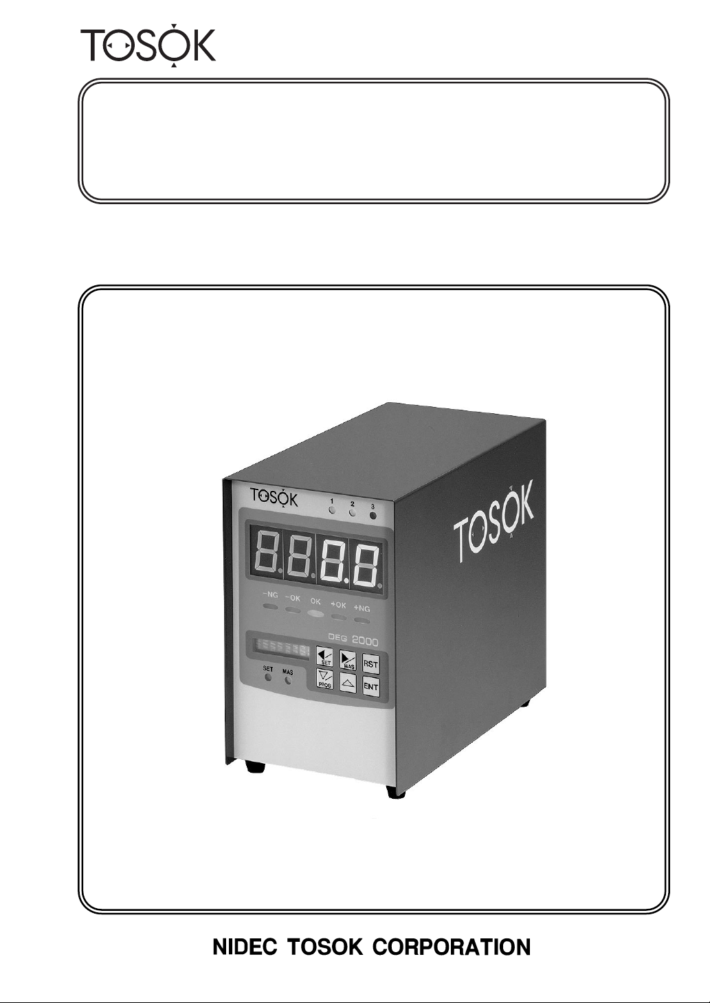
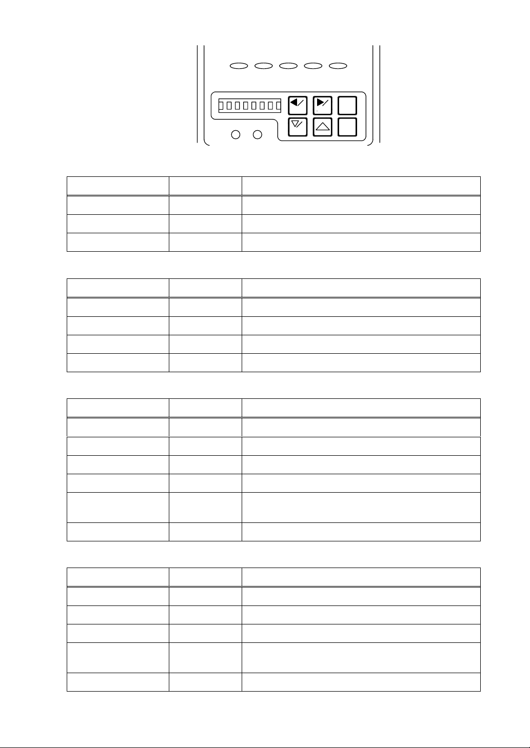
4. Names and Functions of Controls and Parts
1
◯
Item and judgment LEDs
-NG-
OK
OK +OK +NG
➀
12
3
Indicate the judgment result and measurement under way (as shown on the main
display), among other things. The conditions of Items 1 to 3 are indicated by LEDs 1 to
3, respectively. The lighting colors of the LEDs and the conditions indicated by them are
shown in Table 1.
Table 1. LED colors and conditions indicated.
Color Condition Mode
Green (light and dark) Judgment result OK; Main display item Measure
Green (light) Judgment result OK; Other item Measure
Green (dark) and blank Judgment result OK; Main display item Hold measured value
Green (dark) Judgment result OK; Other item Hold measured value
Red (light and dark) Judgment result NG; Main display item Measure
Red (light) Judgment result NG; Other item Measure
Red (dark) and blank Judgment result NG; Main display item Hold measured value
Red (dark) Judgment result NG; Other item Hold measured value
Orange (light)
Set value of item being entered Set
Instrument being calibrated with master Master
Detector being adjusted Adjust detector
2
Page 5
-NG-
OK
OK +OK +NG
12
3
➁
2
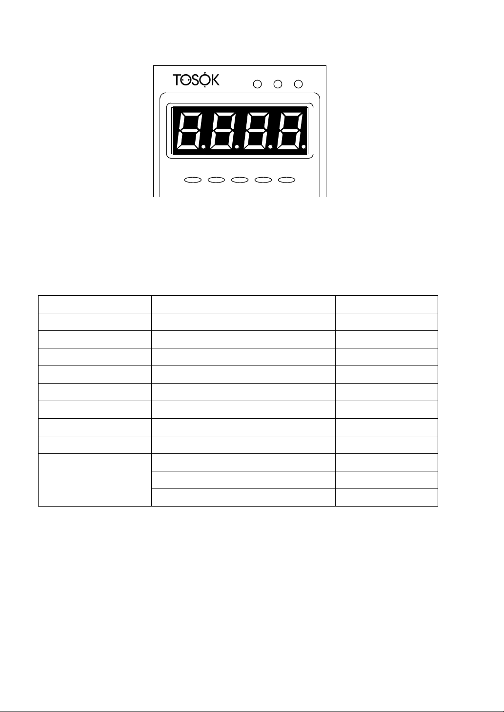
◯
Main display
Shows a value or condition in one of three colors. The display colors in each mode are
as given in Table 2.
Table 2. Display colors and items in each mode.
Mode Color Item
Measure Green (light)
Red (light)
Orange (light)
Hold measured value Green (dark)
Red (dark)
Orange (dark)
Master Green (light)
Red (light)
Measured value (Judgment result OK)
Measured value (Judgment result ±NG)
Measured value (Judgment result ±OK)
Measured value (Judgment result OK)
Measured value (Judgment result ±NG)
Measured value (Judgment result ±OK)
Mastering enabled
Mastering disabled
Adjust detector Orange (light) Measured value
3
Page 6
OK OK +OK +NG
-NG-
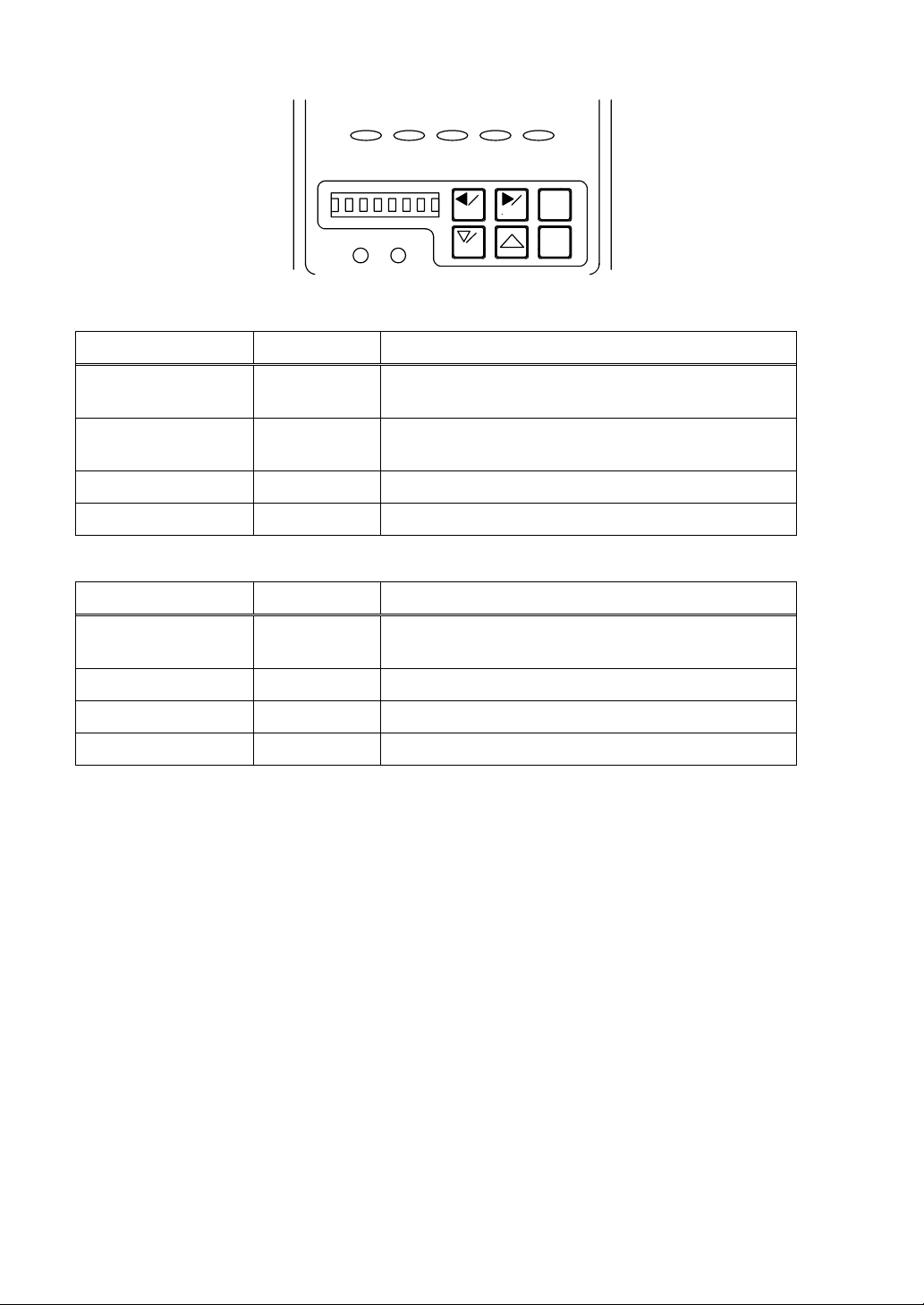
➃
SET MAS
➂
SET MAS
PROG
RST
ENT
➄
3
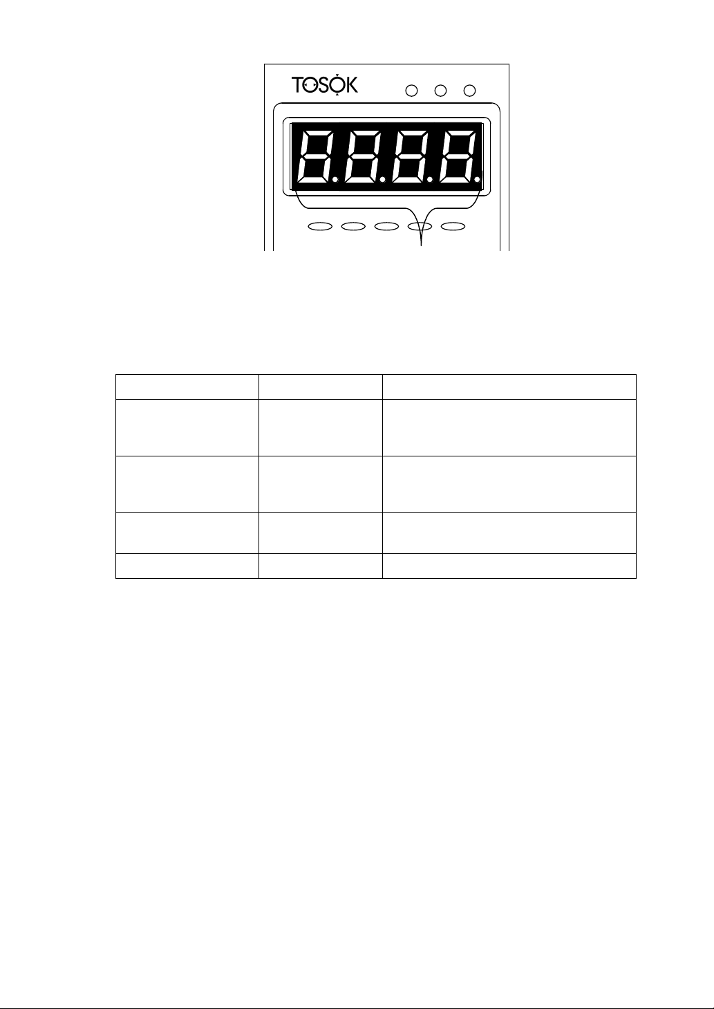
◯
Display item judgment LEDs
Judge the data shown on the main display. OK is indicated by green, ±OK by orange,
and ±NG by red. ±OK is used only when the number of ranks is three.
4
◯
Alphanumeric display
The measured value, set value, set description, and other data are indicated by 8-digit 7
× 5 dot characters.
5
◯
Mode LEDs
Indicate the condition of the current mode and the mastering result. The LED lighting
colors, modes, and mastering results are as shown in Table 3.
Table 3. LED colors and conditions indicated.
SET mode LED MAS mode LED Mode Mastering result
Orange Off Set OK
Orange Red flashing Set NG
Green Off Change program OK
Green Red flashing Change program NG
Off Orange Master OK
Off Orange and red Master NG
Off Red flashing Measure NG
Off Off Measure,
OK
Hold measured value
4
Page 7
OK OK +OK +NG
-NG-
➅➆
RST
ENT
SET MAS
SET MAS
PROG
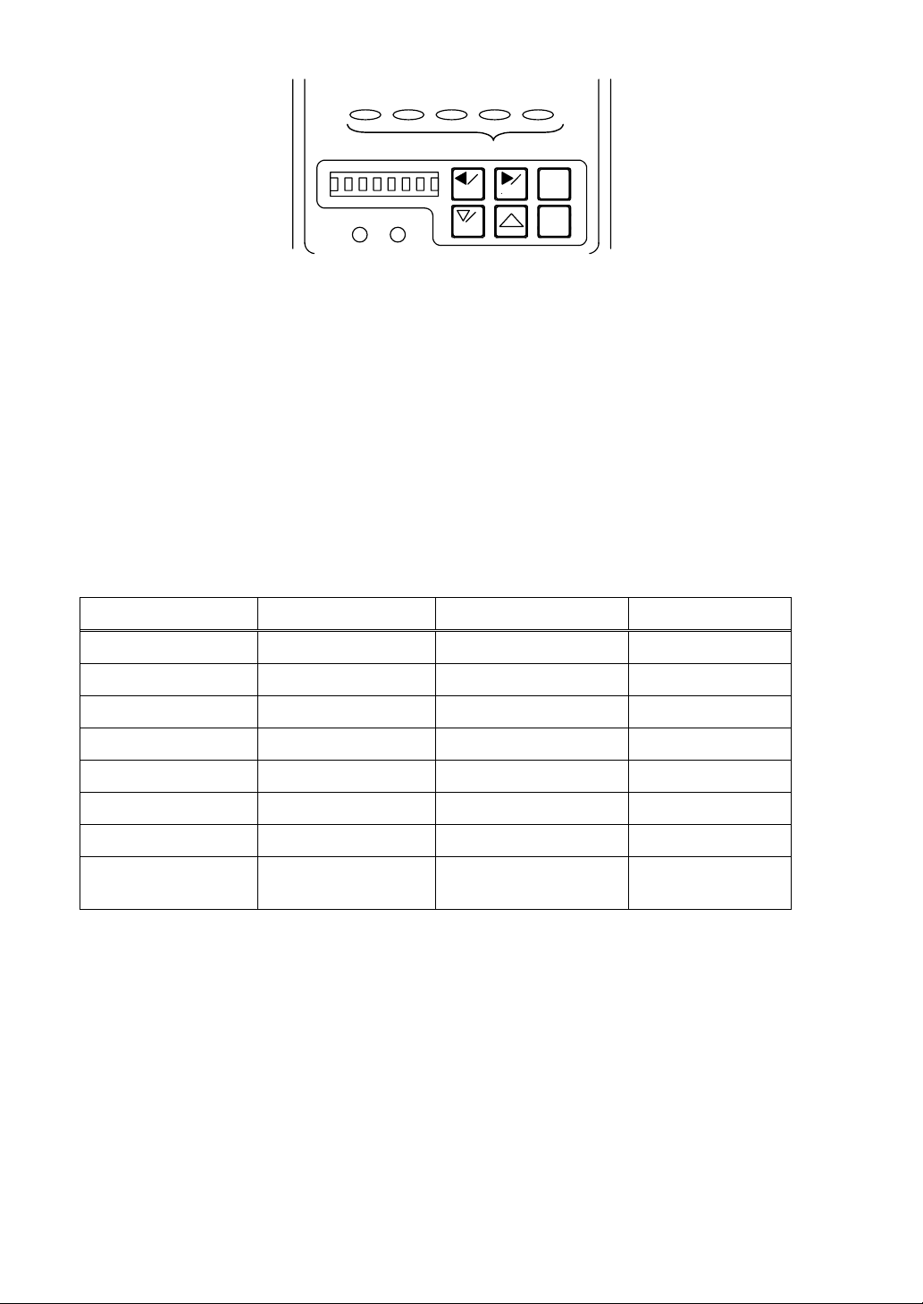
➇ ➈
6
◯
Left arrow /SET key
Mode Keying Operation
Measure Press 2 sec. Mode is changed to set mode.
Set Press once. Set description is changed.
Adjust detector Press once. Measuring head is changed.
7
◯
Right arrow/MAS key
Mode Keying Operation
Measure Press 2 sec. Mode is changed to master mode.
Set Press once. Set description is changed.
Master Press once. Mode is changed to adjust detector mode.
Adjust detector Press once. Measuring head is changed.
8
◯
Down arrow/PROG key
Mode Keying Operation
Measure Press 2 sec. Mode is changed to change program mode.
Measure Press once. Item is changed from ITEM 3 to ITEM 1.
Set Press once. Set value is entered (or decremented).
Master Press once. Master is changed from MAS 2 to MAS 1.
Adjust detector Press once. Master is changed from MAS 2 to MAS 1, or set
value is entered (or decremented).
Change program Press once. Program is changed from PROG 4 to PROG 1.
9
◯
Up arrow key
Mode Keying Operation
Measure Press once. Item is changed from ITEM 1 to ITEM 3.
Set Press once. Set value is entered (or incremented).
Master Press once. Master is changed from MAS 1 to MAS 2.
Adjust detector Press once. Master is changed from MAS 1 to MAS 2, or set
value is entered (or incremented).
Change program Press once. Program is changed from PROG 1 to PROG 4.
5
Page 8
OK OK +OK +NG
-NG-
◯
10
RST
ENT
11
◯
10
◯
RST (reset) key
SET MAS
SET MAS
PROG
Mode Keying Operation
Hold measured
Press once. Measured value hold is cleared.
value
Set Press once. Set description is returned to previous condition.
Setting is finished (WRITE or CANCEL).
Master Press once. Reading of master measured value is canceled.
Adjust detector Press once. Set description is returned to previous condition.
11
◯
ENT (enter) key
Mode Keying Operation
Measure Press once. Mode is changed to hold measured value mode
(when mastering result is OK).
Set Press once. Set description is determined.
Master Press once. Master measured value is read.
Adjust detector Press once. Adjustment description is determined.
6
Page 9
12
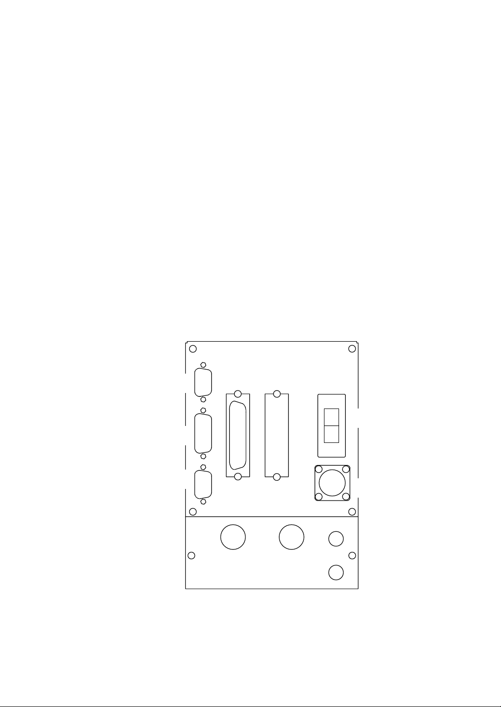
◯
RS232C connector
A serial communication connector for connecting a personal computer or printer.
13
◯
Switch input connector
A connector for entering a measure or mastering command with an external button. It is
also used for RS422 communication and Digimatic output.
14
◯
Analog input/output connector
A connector for external analog signal input and amplifier signal output.
15
◯
DC input/output connector
A judgment result input/output connector for connecting LEDs, sequencers, etc.
16
◯
DC input/output connector (option)
17
◯
Power switch
Used to turn on and off the power of the instrument.
18
◯
Power connector
Used to input AC power. It can be used in the range of 85 to 264 VAC, but the
accessory power cable must be used in the range of 85 to 125 VAC.
Rear of DEG2000
12
◯
13
◯
14
◯
ANALOG SW.ETC RS232C
15
◯
EXT I/O
16
◯
AB
AC85~264V
C
D
17
◯
18
◯
7
Page 10
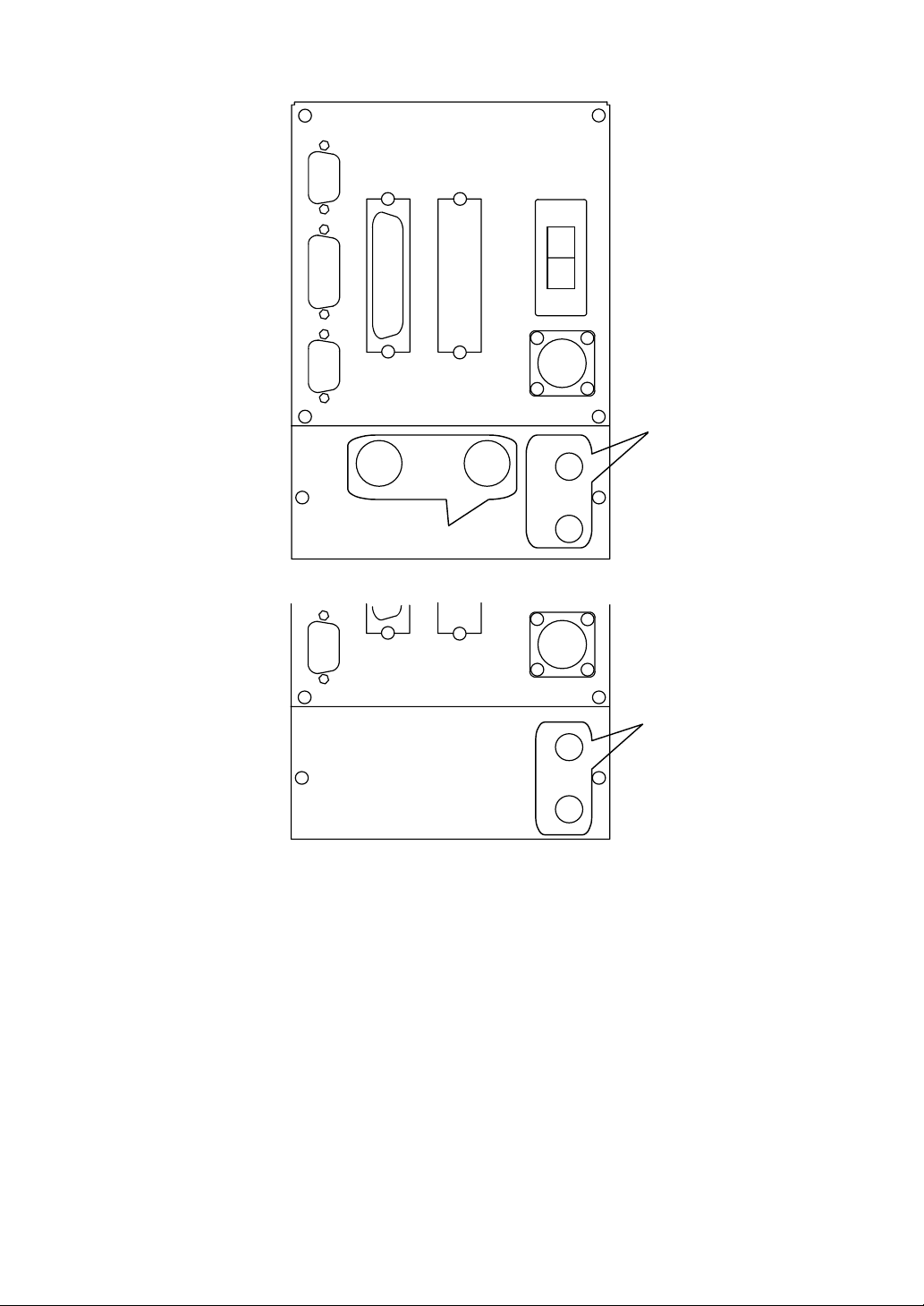
Rear of standard model DEG2000-N
ANALOG SW.ETC RS232C
EXT I/O
AB
AC85~264V
C
20
◯
19
◯
Rear of dedicated model DEG2000-A for air micrometer
19
◯
Electric micrometer connector
Two detectors can be connected.
20
◯
A/E converter (AE2000) connector
Two AE2000 converters can be connected.
D
20
◯
C
D
8
Page 11
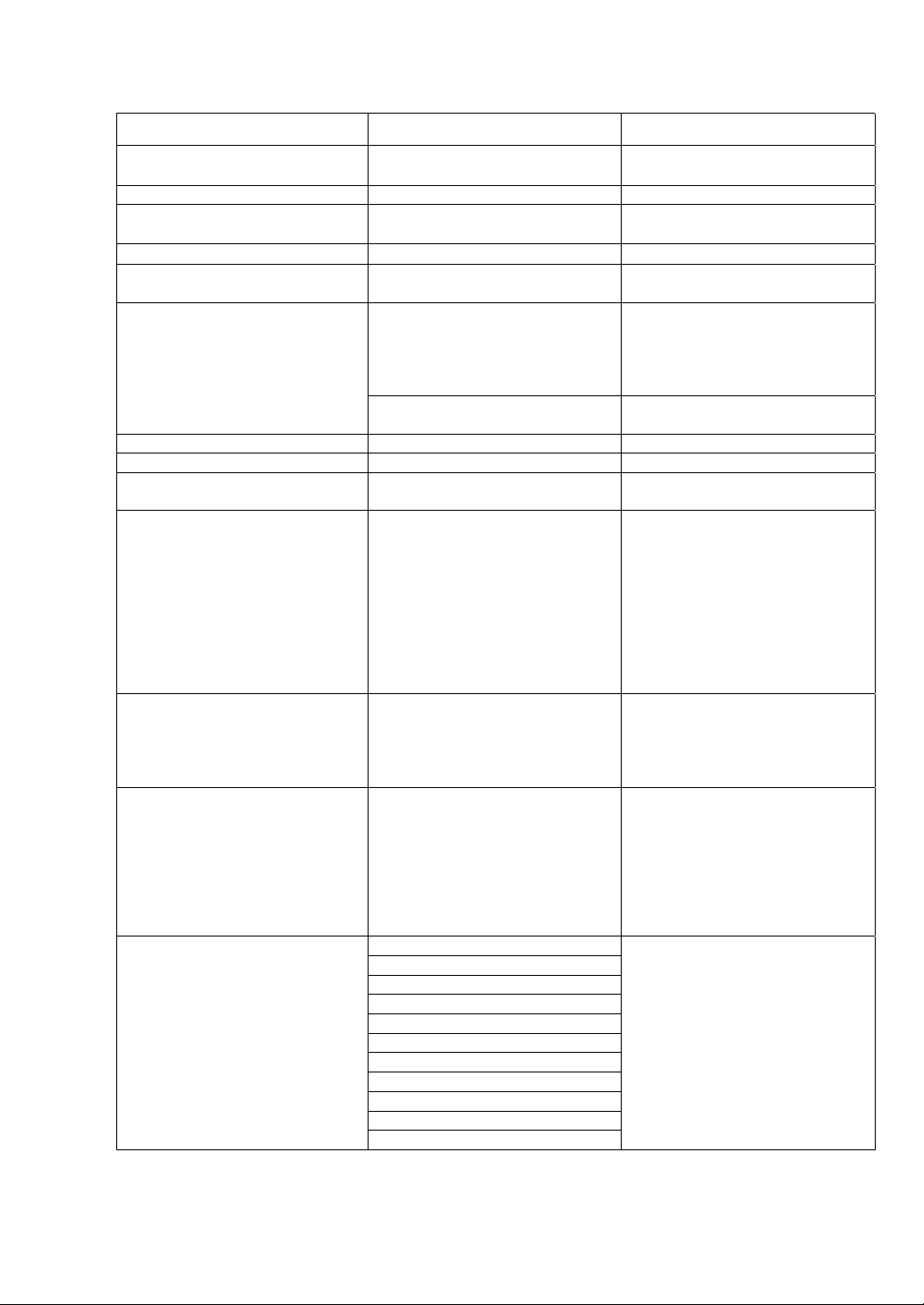
5. Specifications
Item Specification Remarks
Power supply voltage and
frequency
Power supply capacity 30 VA
Dimensions and mass
Operating temperature
Number of programs 4 (Programs 1 to 4) Programs 1 to 3 are changeable
Input module 1. Standard
Number of measurement items 3 (Items 1 to 3)
Number of masters 2 (MAS 1 and MAS 2)
Number of input channels
(XDUCER)
Indicating range (resolution)
Mastering data input Select from among four detectors
Operation functions Item 1 can select MAS 1 or MAS
Measuring functions
85 to 264 VAC, 50/60 Hz 100 VAC power cable supplied as
accessory
120 mm wide × 200 mm high ×
220 mm deep, 2.7 kg
0 to 45°C
from external input.
Changeable by software and
(1) Electric micrometer
(2) Air micrometer
2. Dedicated for air micrometer 2 channels for air micrometer
4
Air micrometer
1. FS±10 µm (0.05 to 2)
2. FS±20 µm (0.1 to 2)
3. FS±50 µm (0.1 to 2)
4. FS±100 µm (0.1 to 2)
Electric micrometer
1. FS±20 µm (0.1 to 2)
2. FS±100 µm (0.1 to 2)
3. FS±1000 µm (1 to 2)
A to D (multiple choice possible).
Symbols and coefficients (-9.999
to +9.999) can be freely
combined.
2, Item 2 can select MAS 1, MAS
2, or Item 1, and Item 3 can select
MAS 1, MAS 2, Item 1, or Item 2
(multiple choice possible).
Symbols and coefficients (-9.999
to +9.999) can be freely
combined.
1. BYPASS
2. +PEAK
3. -PEAK
4. TIR
5. TIR/2
6. MAX
7. min
8. MAX - min
9. (M - m)/2
10. (M + m)/2
11. ABS
unusable simultaneously:
2 channels for air micrometer
(external) and 2 channels for
electric micrometer (internal)
(external)
Set for each program.
Resolution is available in six types
of 0.05, 0.1, 0.2, 0.5, 1, and 2.
Set for each master.
Example:
MAS 1 = A + B + C
MAS 2 = -A + B
Set for each item.
Example:
Item 1 = MAS 1 + MAS 2
Item 2 = -MAS 1 +MAS 2
Item 3 = Item 1 - Item 2
Set for each item.
9
Page 12
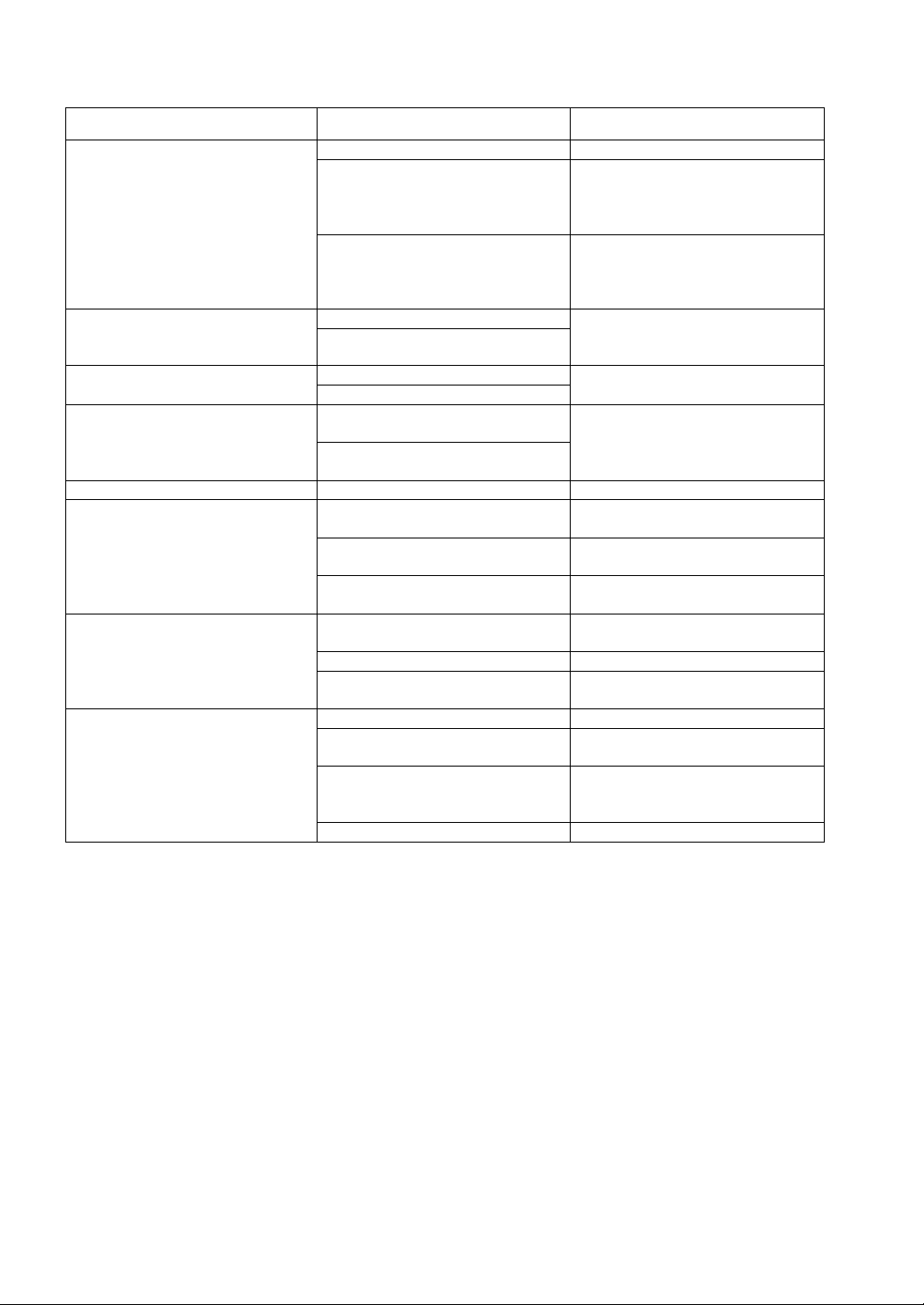
Item Specification Remarks
Judgment method ±NG and rank Set for each item.
1. EQUAL Equal ranking:
Maximum of 99 ranks
(Judgment result output:
Maximum of 99 ranks)
2. SELECT Arbitrary ranking:
Maximum of 39 ranks
(Judgment result output:
Maximum of 39 ranks)
1. All masters togetherNumber of masters with which
instrument is to be automatically
calibrated
Mastering range
Number of smoothing cycles 1 to 30 cycles Set for each program.
Communication functions
Judgment result output
Options
2. Each master separately
1. MIN M.Mastering method
2. MAX & MIN
Zero adjustment:
Indicating range ± 30%
Sensitivity adjustment:
Indicating range ± 20%
1. Measured value output to
personal computer
2. Measured value output to
printer
3. External input and foot switch External buttons and foot switch
1. ±NG, ±OK, and OK Output for 3 measurement items +
2. ±NG and 16 ranks Output for 1 measurement item
3. ±NG and 99 ranks (code
output)
1. Digimatic output Output to printer (DP-1)
2. BCD output (addition of output
board required)
3. Additional judgment result
output (addition of output board
required)
4. Serial communication RS422 output
Set for each program.
Automatic mastering is possible
from external signal.
Set for each program.
RS232C communication cable is
sold separately.
are sold separately.
All OK/NG
BCD data output
Individual output of ranks 17 to 39
10
Page 13
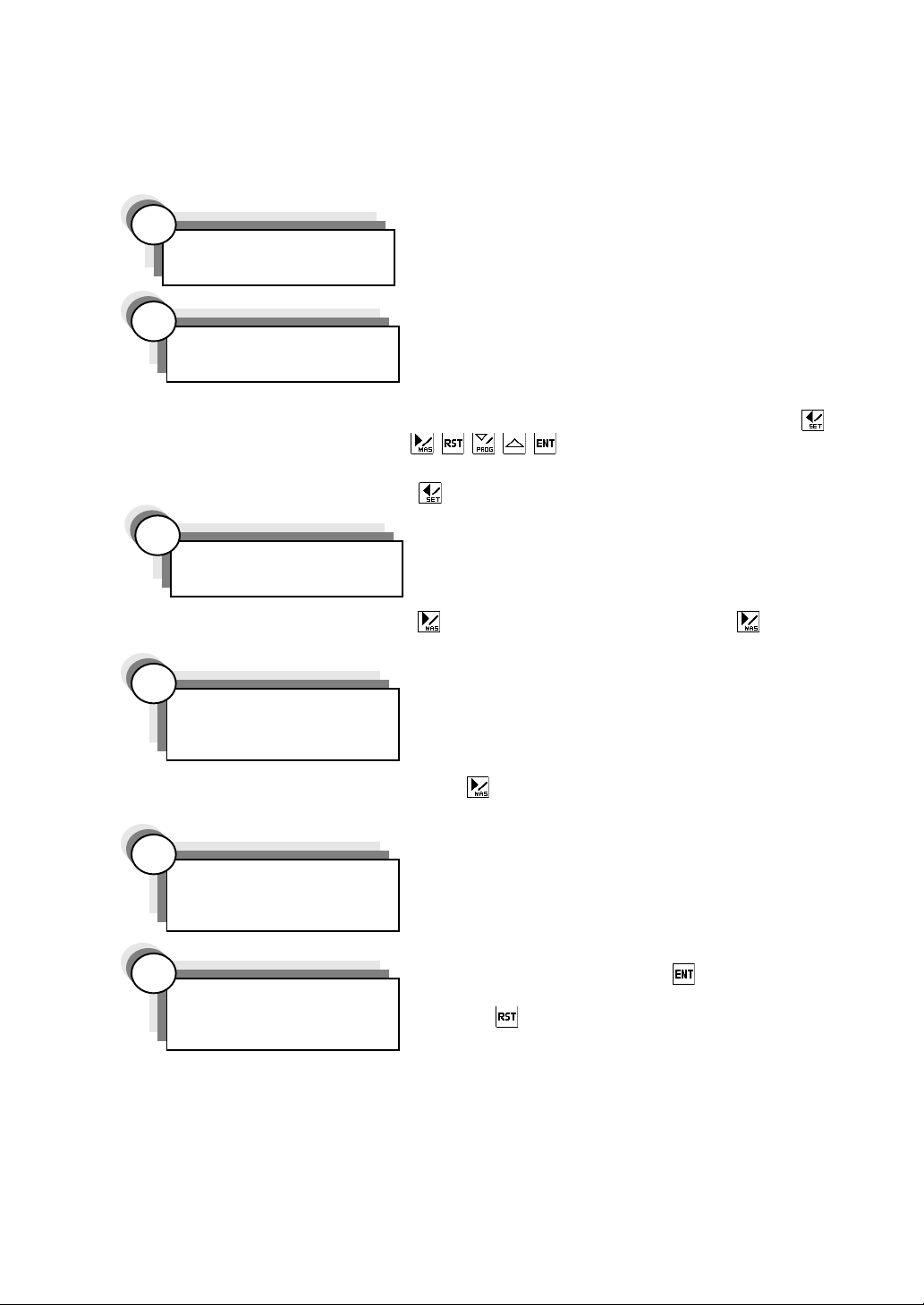
6. Operation
6.1 Description
Here is described a series of steps from connecting a measuring head to measuring with
the head.
1
Connecting
2
Turning on power
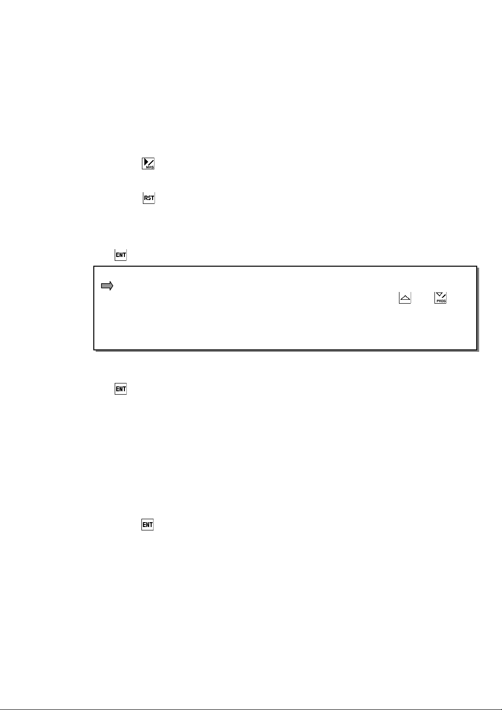
In the measure mode, press the
3
Entering set value
In the measure mode, press the
to change to the adjust detector mode.
4
Adjusting detector
Connect the measuring head or the AE2000 (A/E
converter), and the accessory power cable to the rear
of the instrument.
Turn on the power switch at the rear of the instrument
to supply the power of 85 to 264 VAC (50/60 Hz).
Immediately after the startup, the instrument falls in
the master request condition (“MAS REQ”
on the alphanumeric display). Press one of the
The instrument changes to the measure mode.
Enter the set value. Refer to “6.4 Setting” and “Set
mode” in “13. Operation flow”.
Adjust the detector or AE2000. Refer to “Adjust
detector mode” in “13. Operation flow”.
or AE2000
appears
key for 2 sec or more to change to the set mode.
key for 2 sec or more, and press the key once
keys to clear the master request.
In the adjust detector mode, press the
(showing “MIN M.” on the alphanumeric display).
5
Mastering
6
Measuring
Calibrate the instrument with a master. Refer to “6.3
Automatic mastering” and “Master mode” in “13.
Operation flow”.
In the measure mode, press the
change to the hold measured value condition.
Press the
The measured value cannot be held when the
mastering result is NG. Refer to “6.2 Measuring”.
key twice to change to the master mode
11
key once to
key to clear the measured value hold.
Page 14
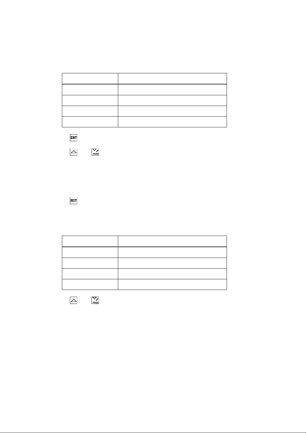
6.2 Measuring
Measure mode
• The conditions indicated by the colors of the item and judgment LEDs in this mode are
as shown in Table 4.
Table 4. Conditions indicated by colors of item and
judgment LEDs in measure mode.
Color Condition
Green (light/dark) Judgment result OK; Main display item
Green (light) Judgment result OK; Other item
Red (light/dark) Judgment result NG; Main display item
Red (light) Judgment result NG; Other item
• Press the
measured value cannot be held when the mastering result is NG.
• Press the
another.
• Select the program to be used for the measurement in the change program mode.
Refer to “Measure mode and change program mode” in “13. Operation flow”.
Hold measured value mode
• Press the
• The conditions indicated by the colors of the item and judgment LEDs in this mode are
as shown in Table 5.
• Press the
another.
key once to change to the hold measured value condition. The
and keys to change from one main display item (ITEM 1 to 3) to
key to clear the measured value hold and return to the measure mode.
Table 5. Conditions indicated by colors of item and
judgment LEDs in hold measured value mode.
Color Condition
Green (dark/blank) Judgment result OK; Main display item
Green (dark) Judgment result OK; Other item
Red (dark/blank) Judgment result NG; Main display item
Red (dark) Judgment result NG; Other item
and keys to change from one main display item (ITEM 1 to 3) to
12
Page 15
6.3 Automatic mastering
Notes: 1. This instrument is a comparative measuring instrument. Be sure to use it
after calibrating it with a master.
2. During a program change, the instrument reads the previous mastering
data.
3. Clear the mastering data when changing the settings of [I-RANGE],
[RESOLUTION], [XDUCER] and [MASTER] and when turning on the
power of the instrument.
➀ Press the
➁ The MAS mode LED (orange) lights, “MIN M.” appears on the alphanumeric display,
and the instrument changes to the master mode.
When the
the last condition or to the measure mode when “MIN M.” is shown on the
alphanumeric display.
➂ Set the minimum master in the detector. When the main display is stabilized, press
the
When “EACH” is selected with [SYSTEM]–[MasSet] in the set mode beforehand…
The mastering operation is carried out according to the master (MAS 1 or MAS 2)
whose mastering data is shown on the main display. Press the
to select the master to be used. The master selection is indicated by one of the
item and judgment LEDs as follows:
LED 1 lights to indicate MAS 1.
➃ The alphanumeric display shows “MAX M.”.
➄ Set the maximum master in the detector. When the main display is stabilized, press
the
➅ “MAS OK” appears for 2 sec on the alphanumeric display to indicate the completion of
the mastering procedure. (The instrument automatically returns to the measure
mode.)
For other details, refer to “Master mode” in “13. Operation flow”.
key for 2 sec or more in the measure mode.
key is pressed during the mastering operation, the instrument returns to
key.
key.
and keys
Mastering errors
• The alphanumeric display shows the following errors:
ERR ZERO: Zero error (outside of mastering range)
ERR MAG: Sensitivity error (outside of mastering range)
ERR REV: Maximum and minimum master values reversed
ERR OFFR: Outside of measuring range
Press the
• When calibrating the instrument with individual masters separately, the mastering
channel changes to return to step ➁ above unless the mastering result is OK for both
maximum and minimum masters.
When a mastering error occurs despite re-mastering, adjust the detector. Refer to
“Adjust detector mode” in “13. Operation flow”.
key to return to step ➁ above. Re-master.
13
Page 16
6.4 Setting
The set value is entered and changed in the set mode.
6.4.1 Set mode
The set mode covers the following settings:
[XDUCER]
The sensitivity of the detector is set. Refer to “Set mode (2)” in “13. Operation flow”.
[MASTER]
The master input channel and the maximum and minimum master values are set. Refer
to “Set mode (3)” in “13. Operation flow”.
[ITEM]
The item constitutive data, measuring function, number of ranks, and boundary values
(upper/lower limits) are set. Refer to “6.4.2 Measuring functions”, “Set mode (4)” in “13.
Operation flow” and “Set mode (5)” in “13. Operation flow”.
[COMM]
Input/output data, like A/D external input and judgment result output data, are set.
Refer to “Set mode (6)” in “13. Operation flow”.
[SYSTEM]
The mastering and automatic measuring functions are set. Refer to “6.4.3 Automatic
measuring functions” and “Set mode (7)” in “13. Operation flow”.
6.4.2 Measuring functions
The measuring functions are set with [ITEM]–[FUNCTION] in the set mode. Here is
described [ITEM], centering on [FUNCTION].
[STRUCT]
The constitutive data of each item and the coefficient of each constitutive data are set.
[FUNCTION]
The measuring function of each item is selected.
Example
When “+PEAK”, “–PEAK”, “TIR”, and “TIR/2” are selected, the automatic measuring
functions are enabled. Refer to “6.4.3 Automatic measuring functions” and “Set
mode (7)” in “13. Operation flow”.
When the constitutive data of Item 1 are MAS 1 and MAS 2…
➀ Select “BYPASS”.
The measured value of Item 1 is (MAS 1 + MAS 2).
➁ Select “+PEAK”.
The measured value of Item 1 is the maximum value of (MAS 1 +
MAS 2).
➂ Select “MAX”.
The measured value of Item 1 is the larger measured value of
(MAS 1 and MAS 2).
14
Page 17

[RANK]
The OK ranking method of each item and the number of OK ranks are set.
[LIMIT]
The OK rank boundary of each item is set.
Example
Refer to “Set mode (5)” in “13. Operation flow”.
➀ When [RANK] = EQUAL, [RANK n] = 4, [R1/-NG] = -30, and
[+NG/Rn] = +30 are set…
-NG < -30 ≤ R1 < -15 ≤ R2 < 0 ≤ R3 ≤ +15 < R4 ≤ +30 < +NG
➁ When [RANK] = SELECT, [RANK n] = 3, [R1/-NG] = -15,
[R1/R2] = -5, [R2/R3] = 0, and [+NG/Rn] = +15 are set…
-NG < -15 ≤ R1 < -5 ≤ R2 ≤ 0 < R3 ≤ +15 < +NG
6.4.3 Automatic measuring functions
The automatic measuring functions are enabled when “+PEAK”, “-PEAK”, “TIR”, and
“TIR/2” are selected with [FUNCTION]. The following automatic measuring functions
are set with [SYSTEM] in the set mode.
[AutoMeas]
Sets the percentage of all master data in the indicating range at which to start the
automatic measurement start function. Disabled when the automatic measurement
start function is turned off.
[InToOut]
Sets whether to hold or reset the measured value when the mastering data change from
inside of the measuring range to outside of the measuring range. Disabled when the
automatic measurement start function is turned off.
[WaitTime]
Sets the stabilizing timer at the time for the automatic measurement to start. When the
stabilizing timer is set at 0.00 sec, the automatic measurement start function is turned off.
[MeasTime]
Sets the measuring timer at the time for the automatic measurement to stop. When the
measuring timer is set at 0.0 sec, the automatic measurement stop function is turned off.
Example
➀ When [WaitTime] = 0.0 and [MeasTime] = 0.0 are set…
Press the ENT key to start the measurement and the RST key to
stop the measurement.
➁ When [I-RANGE (indicating range)] = ±100, [WaitTime] = 1.00,
[AutoMeas] = ±80%, and [MeasTime] = 5.0 are set…
The automatic measurement starts 1 sec after the mastering data
fall within the range of -80 to +80 and stops 5 sec after the start.
The instrument remains in the hold measured value mode until
the measured value falls outside the range of -80 to +80.
15
Page 18

7. I/O Description
g
7.1 Serial output
(1) Description
This instrument can output the measured values to a printer and communicate with a
personal computer (PC) through RS232C.
Data to be transmitted from instrument to PC
Measurement item: Items 1 to 3
Measured value: Data displayed on instrument, NO USE
Judgment result: R 1 to R99, NJG (stabilizing timer in operation), or NDT (only
when NO USE is displayed)
(2) Preparation
The RS232C connector at the rear of the instrument is provided for the PC or printer.
Connect the D-sub 9-pin (male) plug of the optional communication cable to the RS232C
connector.
(3) Connector pin arrangement
(4) Serial port settings
Baud rate: 9600
Bits/character: 8
Stop bit: 1
Start bit: 1
Parity bit: None
(5) Transmission data composition
Item 1 (5 characters), space (1 character), measured value (8 characters), space (1
character), rank (3 characters), space (1 character);
Item 2 (5 characters), space (1 character), measured value (8 characters), space (1
character), rank (3 characters), space (1 character);
Item 3 (5 characters), space (1 character), measured value (8 characters), space (1
character), rank (3 characters), CR, LF
Description No.
1
R × D 2
T × D 3
4
GND
5
Measured value
Jud
No. Description
6
7RTS
8CTS
9
ment result
ITEM1
ITEM2
ITEM3 CRLF
(6) Data transmission method to PC
In the measure mode, press the key. The instrument falls in the hold measured
value condition and transmits the measured value to the personal computer. The data
transmission is disabled when the mastering result is NG.
16
Page 19

(7) Data request command from PC
➀ Measured value latch (data hold) command
Transmit the command byte “E”<45H>. The instrument holds the measured value.
➁ Latch clear command
Transmit the command byte “R”<52H>. The instrument clears the measured value
hold.
➂ Measured value request
Transmit the command byte “D”<44H>. The instrument transmits the abovementioned data (5) to the PC.
Example
Example
Character string
ASCII code
ASCII code 49 54 45 4D 31 20 20 20 20 2D 32 35 2E 30 20 2D 4E 47 20
I TEM1 –25 . 0 –NGcharacter-string
ITEM2 12.5 +OK
ITEM3 NO USE NDTCRLF
49 54 45 4D 32 20 20 20 20 20 31 32 2E 35 20 2B 4F 47 20
49 54 45 4D 33 20 20 20 4E 4F 20 55 53 45 20 4E 44 54 0D 0A
17
Page 20

7. 2 External input
(1) Description
The instrument allows no-voltage contacts, such as those of an external button or foot
switch, to be connected to the SW. ETC connector at the rear. This external input can
be used to perform measurement, reset, maximum mastering, and minimum mastering.
Notes: • Use a cable of 2 m or less in length.
• Do not connect to a sequencer.
(2) Preparation
The SW. ETC connector at the rear of the instrument is provided for external buttons. It
accepts a D-sub15-pin (male) plug.
(3) Connector pin arrangement and connection diagram
(4) Operation with external buttons
a. MEASURE button
➀ In the measure mode, press the MEASURE button.
➁ The measured value is held. (This is called the hold measured value condition.)
Note: The measured value cannot be held when the mastering result is NG.
b. RESET button
➀ Clears the measured value hold.
c. MAX M. (maximum master) button
➀ In the measure mode, set the maximum master in the measuring head.
➁ When the measured value is stabilized, press the MAX M. button. When the
maximum mastering procedure is completed, the instrument returns to the measure
mode.
d. MIN M. (minimum master) button
➀ In the measure mode, set the minimum master in the measuring head.
➁ When the measured value is stabilized, press the MIN M. button. When the minimum
mastering procedure is completed, the instrument returns to the measure mode.
When a mastering error occurs, adjust the detector. Refer to “Adjust detector mode” in
“13. Operation flow”.
18
Page 21

7.3 Judgment result output
The result of three-item judgment, two-item judgment, or ranking is output to the DC
input/output connector. (refer to ◯
7.3.1 Specifications
Item Specification
Input type Photocoupler insulated input
15
on page 7).
Input resistance
Input on voltage 10 V or more
Input
section
Output
section
Current consumption 110 mA
Input off voltage 2 V or less
Number of input signals 8
Input protection circuit No
Response time 1 msec or less
External circuit power supply 12 to 24 VDC
Output type Open collector output
Output voltage 30 VDC
Rating
Output current Maximum of 50 mA per output signal
Number of output signals 24
Output protection circuit No
5 kΩ
19
Page 22

7.3.2 Input signal arrangement
Note: The input signals are enabled when “READY” is turned on. The following
table shows the input signal arrangement of the DC input/output connector
(refer to ◯
Pin No. Signal name Description
15
on page 7).
1 Measure command
Hold measured value and data output command
(Enabled when mastering result is OK.)
2 Minimum mastering Minimum mastering command
3 Maximum mastering Maximum mastering command
4 RESET Measured value hold clear command
5 Program change (lower)
6 Program change (higher)
7 Item bit (less significant)
8 Item bit (more significant)
Specifies program numbers 1 to 3 to be changed.
(Refer to Table 6.)
Specifies measurement items 1 to 3 to be output.
(Refer to Table 7.)
9+COM
Input common line: +12/24 V
10 +COM
Table 6. Program change and program numbers.
Program number
123
Program change (lower) On Off On
Program change (higher) Off On On
Table 7. Item bits and measurement items to be output.
Setting for this instrument*
Item bit (less
significant)
Item bit (more
significant)
Off On Off On
Off Off On On
*1 Item set with [JUDG OUT] is output.
Measurement item to be output
1
123
20
Page 23

7.3.3 Procedure for calibrating instrument with masters by external input
(1) Description
Set the minimum and maximum masters in that order.
(2) Mastering
➀ Check that “READY” is displayed.
➁ Set the minimum master in the measuring head.
➂ After about 2 sec of stabilization time, input the “Minimum mastering” signal.
➃ Set the maximum master in the measuring head.
➄ After about 2 sec of stabilization time, input the “Maximum mastering” signal.
➅ Check that “MAS OK” is displayed. If “MAS OK” is displayed, the mastering
procedure is completed. If “MAS OK” is not displayed, check the setting of each
master, and adjust the measuring head and A/E converter, among other things.
<I: Input to instrument, O: Output from instrument>
0.1 sec or more
I: Minimum mastering
0.1 sec or more
I: Maximum mastering
O: READY
O: Master OK
0.05 sec or less 0.05 sec or less
O: Check input signal
(3) Program change
When the program change on condition is held for 0.2 sec, the measuring program is
changed. Programs 1 to 3 can be freely changed from one to another.
*No change can be made to program 4.
<I: Input to instrument>
I: Program change (lower)
I: Program change (higher)
Condition of instrument
No
program
change
PROG1PROG2PROG
PROG
3
3
21
Page 24

7.3.4 Measuring procedure
(1) Description
In the measure mode, the instrument continues to produce the judgment result output.
In the case of static measurement, it holds the measured value display and judgment
result output when the measure command changes from off to on.
(2) Static measurement
➀ Check that “READY” is displayed.
➁ Check that “MAS OK” is displayed.
➂ Set the work in the measuring head.
➃ After about 2 sec of stabilization time, turn on the measure command. (The
measured value display and judgment result output are held, and “All OK/NG” is
output.)
➄ Read the data.
➅ Input the RESET signal. (The measured value display and judgment result output
hold is cleared.)
<I: Input to instrument, O: Output from instrument>
0.1 sec or more
I: Measure command
0.1 sec or more
I: RESET
O: READY
O: Master OK
O: All OK/NG
O: Hold measured value
0.05 sec or less
0.05 sec or less
O: Check input signal
(3) Dynamic measurement
When “+PEAK”, “–PEAK”, “TIR”, or “TIR/2” is selected at [FUNCTION], the instrument
makes dynamic measurement. When any other item is selected, the instrument makes
static measurement.
The dynamic measurement differs from the static measurement in that the instrument
starts the measurement at the first measure command and holds the measured value at
the second measure command. When making a measurement at an external input
signal, usually set WaitTime and MeasTime both at 0 sec. Before the start of the
measurement, input the RESET signal to clear the peak value accumulation.
22
Page 25

7.3.5 Selecting judgment result output and BCD output
Number 1 2 3 4 5 6
Parallel Parallel Parallel Parallel Code
Output type
OK 3 or
less
OK 7 or
less
OK 16 or
less
OK 39 or
less
OK 99 or less
BCD
All items
Output
items
External
input/output type
Setup of
number
of ranks
Output item
change by input
signal
Remarks Refer to
Each
item
Items 1
and 2
Setup
item
name
Setup
description
––
–
All All All DC DC
–
– Rank n Rank n Rank n Rank n Rank n –
–7 or less
No No Yes Ye s Yes Ye s Ye s
24 page
––––––
Item 1
Item 2
Refer to
25 page
–––––
Other
than
those
shown at
left
Item Item Item Item –
16 or
less
Refer to
26 page
39 or
less
Refer to
27 page
40 or
more
Refer to
28 page
17 or
more
Refer to
28 page
BC
Refer to
29 page
–
1. Output type selection
• The output types marked by are normally usable, and the other output types are
options.
• The output types marked by call for addition of a circuit board.
• Numbers 4 and 6 cannot be selected at the same time.
2. Output item change
• The settings of output items 1 to 5 can be changed with [JUDG OUT] in the set mode.
• The setting of output item 6 can be changed with [BCD OUT] in the set mode.
• When one of Items 1 to 3 is selected as output item, an item bit can be entered to
temporarily change the output item among Items 1 to 3. When the item bit is not
entered, the data of the set output item is output.
*In the case of BCD output, enter a BCD item bit instead of an item bit.
23
Page 26

7.3.6 Three-item judgment result output –– Output signal arrangement
The three-item judgment result output signal is output when “ALL ITEM” is selected with
[JUDG OUT] in the set mode (6).
Note: “Item” refers to “ITEM” of DEG2000. The following table shows the output
signal arrangement of the DC input/output connector (refer to ◯
7).
Pin No. Signal name Description
11 READY Turns on in measure mode during normal operation.
12 Error
Turns on when two signals are simultaneously input and
turns off when all signals are turned off.
13 Master OK Turns on when mastering result is OK.
14 Check input signal
15 All OK
16 All NG
Turns on when input signal is received and processing is
completed, and turns off when input signal is turned off.
Turns on at input of measure command when all items
are OK.
Turns on at input of measure command when any one
item is NG.
17 Item 1 -NG
18 -OK
19 OK
20 +OK
21 +NG
22 Item 2 -NG
23 -OK
24 OK
25 +OK
26 +NG
27 Item 3 -NG
28 -OK
29 OK
30 +OK
31 +NG
32
33
34
35 -COM
36 -COM
Output common line: 0 V
15
on page
24
Page 27

7.3.7 Two-item judgment result output –– Output signal arrangement
The two-item judgment result output signal is output when “ITEM 1&2” is selected with
[JUDG OUT] in the set mode (6).
Note: “Item” refers to “ITEM” of DEG2000. The following table shows the output
signal arrangement of the DC input/output connector (refer to ◯
7).
Pin No. Signal name Description
11 READY Turns on in measure mode during normal operation.
12 Error
Turns on when two signals are simultaneously input and
turns off when all signals are turned off.
13 Master OK Turns on when mastering result is OK.
14 Check input signal
15 All OK
16 All NG
Turns on when input signal is received and processing is
completed, and turns off when input signal is turned off.
Turns on at input of measure command when all items
are OK.
Turns on at input of measure command when any one
item is NG.
17 Item 1 -NG
18 +NG
19 OK1
20 OK2
21 OK3
22 OK4
23 OK5
24 OK6
25 OK7
26 Item 2 -NG
27 +NG
28 OK1
29 OK2
30 OK3
31 OK4
32 OK5
33 OK6
34 OK7
35 -COM
36 -COM
Output common line: 0 V
15
on page
25
Page 28

7.3.8 Ranking output (OK rank 16 or less) –– Output signal arrangement
The ranking output signal is output when “ITEM 1”, “ITEM 2” or “ITEM 3” is selected with
[JUDG OUT], or an item bit is entered in the set mode (6).
Note: “Item” refers to “ITEM” of DEG2000. The following table shows the output
signal arrangement of the DC input/output connector (refer to ◯
7).
Pin No. Signal name Description
11 READY Turns on in measure mode during normal operation.
12 Error
Turns on when two signals are simultaneously input and
turns off when all signals are turned off.
13 Master OK Turns on when mastering result is OK.
14 Check input signal
15 All OK
16 All NG
Turns on when input signal is received and processing is
completed, and turns off when input signal is turned off.
Turns on at input of measure command when all items
are OK.
Turns on at input of measure command when any one
item is NG.
17 Item -NG
18 +NG
19 OK1
20 OK2
21 OK3
22 OK4
23 OK5
24 OK6
25 OK7
26 OK8
27 OK9
28 OK10
29 OK11
30 OK12
31 OK13
32 OK14
33 OK15
34 OK16
35 -COM
36 -COM
Output common line: 0 V
15
on page
26
Page 29

7.3.9 Ranking output (OK rank 39 or less) –– Output signal arrangement (option)
The ranking output signal is output when “ITEM 1”, “ITEM 2” or “ITEM 3” is selected with
[JUDG OUT], or an item bit is entered in the set mode (6). For OK rank 16 or less, refer
to “7.3.8 Ranking output”.
Note: “Item” refers to “ITEM” of DEG2000. The following table shows the output
signal arrangement of the optional DC input/output connector (refer to ◯
page 7).
Pin No. Signal name Description
11 Item OK17
12 OK18
13 OK19
14 OK20
15 OK21
16 OK22
17 OK23
18 OK24
19 OK25
20 OK26
21 OK27
22 OK28
23 OK29
24 OK30
25 OK31
26 OK32
27 OK33
28 OK34
29 OK35
30 OK36
31 OK37
32 OK38
33 OK39
34
35 -COM
36 -COM
Output common line: 0 V
16
on
27
Page 30

7.3.10 Ranking code output (OK rank 99 or less) –– Output signal arrangement
The ranking code output signal is output when “ITEM 1”, “ITEM 2” or “ITEM 3” is selected
with [JUDG OUT] or an item bit is entered in the set mode (6).
Note: “Item” refers to “ITEM” of DEG2000. The following table shows the output
signal arrangement of the DC input/output connector (refer to ◯
7).
Pin No. Signal name Description
11 READY Turns on in measure mode during normal operation.
12 Error
Turns on when two signals are simultaneously input and
turns off when all signals are turned off.
13 Master OK Turns on when mastering result is OK.
14 Check input signal
15 All OK
16 All NG
Turns on when input signal is received and processing is
completed, and turns off when input signal is turned off.
Turns on at input of measure command when all items
are OK.
Turns on at input of measure command when any one
item is NG.
17 Item -NG
18 +NG
19 OK1
20 OK2
21 OK4
22 OK8
23 OK16
“OK1” to “OK64” shown at left are ranking codes.
Total of ranking codes is number of ranks.
Example: When “OK2” and “OK4” are turned on, OK6.
24 OK32
25 OK64
26
27
28
29
30
31
32
33
34
35 -COM
36 -COM
Output common line: 0 V
15
on page
28
Page 31

7.3.11 BCD output –– Input/output signal arrangement (option)
The BCD input/output signal is output when “ITEM 1”, “ITEM 2” or “ITEM 3” is selected
with [BCD OUT] or a BCD item bit is entered in the set mode (6).
Note: “Item” refers to “ITEM” of DEG2000. The following table shows the
input/output signal arrangement of the DC input/output connector
(refer to ◯
Pin No. Signal name Description
BCD item bit (less
7
significant)
BCD item bit (more
8
significant)
9+COM
10 +COM
11 BCD OUT 1
12 2
13 4
14 8
15 10
16 20
17 40
18 80
19 100
20 200
21 400
22 800
23 1000
Decimal place
24
25 (1)
26 POL +: Off, -: On
27
28
29
30
31
32
33
34
35 -COM
36 -COM
16
on page 7).
Specifies measurement item to be BCD output.
Specifies measurement item to be BCD output.
Input common line: +12/24 V
(0)
Output common line: 0 V
29
Page 32

7.3.12 Timing charts
(
)
)
Three-item judgment and two-item judgment (I: Input signal to instrument, O: Output
signal from instrument)
O: READY
O: Master OK
0.1 sec or more
I: Measure command
0.1 sec or more
I: RESET
0.05 sec or less
O: Check input signal
0.05 sec
or less
O: All OK/NG
O: Judgment result
of each item
Ranking (I: Input signal to instrument, O: Output signal from instrument)
O: READY
O: Master OK
I: Measure command
I: RESET
O: All OK/NG
O: Check input signal
I: Item bit
less significant
I: Item bit
(more significant
O: Setup item of
instrument
O: Item 1 ranking data
O: Item 2 ranking data
O: Item 3 ranking data
30
Page 33

7.3.13 Connector pin arrangement diagram
A cable connector (57-30360 and DDK make) is supplied as accessory. Usually, a
cable is not supplied as accessory.
1
19
EXT I/O
36
18
31
Page 34

7.3.14 Input circuit diagram
PC844
7.3.15 Output circuit diagram
4.7k
PC8Q52
17
~
10
9
8
~
1
DC12~24V
L
DC12~ 24V
27
35
36
Open collector output: Maximum of 50 mA per output signal
32
MAX 50mA
Page 35

8. Model Identification
DEG 20 00 –– N –– DP
External input/output
None: Standard
DP: Digimatic output
DC: Additional judgment result output
BC: BCD output
SI: Serial communication
Input
N: 2 channels for air micrometer + 2
channels for electric micrometer
A: 2 channels for air micrometer
Model number
20
Basic model designation
DEG
9. Options
9.1 Instrument
➀ Digimatic output: Output to DP-1 printer (cable supplied as accessory)
➁ Additional judgment result output:
➂ BCD output: Output of BCD data (addition of output board required)
➃ Serial communication: RS422 output
Output of individual ranks above rank 17 (addition of
output board required)
9.2 Separately sold parts
➀ Communication cable (DEG2000-OP-CB-1): D-sub 9-pin connector (EIA-232) for
personal computer
➁ Communication cable (DEG2000-OP-CB-2): D-sub 25-pin connector (EIA-574) for
personal computer
➂ Communication cable (DEG2000-OP-CB-3): D-sub 25-pin connector (EIA-574) for
printer
10. Maintenance
(1) Use alcohol for cleaning the instrument. Use of thinner may discolor or darken the
instrument.
33
Page 36

11. Troubleshooting
Phenomenon Cause Remedy
Repeatability is not stable.
Main display does not
operate.
Main display and
alphanumeric display do not
light.
➀ Measuring head is loosely
secured.
➀ Specified power is not
supplied.
➁ Detector is improperly
adjusted.
➂ Instrument falls in hold
measured value
condition. Main display
appears green (dark) or
red (dark).
➃ Instrument is in set mode. ➃ End set mode.
➀ Power is not supplied. ➀ Supply power of 85 to 264
➁ Power supply or internal
circuit is faulty.
➀ Retighten its fasteners.
➀ Supply power of 85 to 264
VAC.
➁ Adjust detector.
➂ Press RST key to clear
this condition.
VAC.
➁ Ask NIDEC TOSOK for
repair.
12. Cautions
(1)Power cable
The power cable supplied as standard accessory is for 100 V. If you use supply voltage
in excess of 125 V, separately prepare a 250-V power cable.
(2)Control keys
Never operate the control keys with a sharp-pointed tool or the like.
(3)Export
When you try to export this instrument overseas, you may have to have the export
approved by the Ministry of Economy, Trade and Industry under the Export Trade Control
Ordinance. In such a case, contact your nearest NIDEC TOSOK sales office.
(4)Specifications
The specifications are subject to change without notice.
34
Page 37

13. Operation Flow
35
Page 38

363738394041424344
Page 39

Page 40

Page 41

Page 42

Page 43

Page 44

Page 45

Page 46

Page 47

14. Work Sheet
DEG2000 Work Sheet No. 1
Manufacture No.:
Program
Setting description
Input module MODULE
Indicating range I-RANGE
Resolution RESOLUTION
PROG 1 PROG 2 PROG 3 PROG 4
XDUCER
MASTER
CH. A
CH. B
CH. C A/D polarity and coefficient
CH. D A/D polarity and coefficient
MAS 1
MAS 2
A/D polarity and coefficient
D/A ZERO ZERO ADJ
D/A GAIN GAIN ADJ
A/D polarity and coefficient
D/A ZERO ZERO ADJ
D/A GAIN GAIN ADJ
XDUCER used INPUT
Maximum master
value
Minimum master
value
XDUCER used INPUT
Maximum master
value
Minimum master
value
MAX M.
MIN M.
MAX M.
MIN M.
ITEM ITEM 1
STRUCT
(Sign and coefficient
input)
Measuring function FUNCTION
OK ranking method RANK
No. of OK ranks RANK n
LIMITS (3 OK ranks)
*For 4 or more OK
ranks, write on work
sheet No.2.
+NG/+OK
MAS 1Item constitutive data
MAS 2
+OK/OK
OK/-OK
-OK/-NG
45
Page 48

Setting description
Program
PROG 1 PROG 2 PROG 3 PROG 4
ITEM ITEM 2 STRUCT MAS 1
ITEM 3 STRUCT MAS 1
Item constitutive data
(Sign and coefficient
input)
Measuring function FUNCTION
OK ranking method RANK
No. of OK ranks RANK n
LIMITS (3 OK ranks)
*For 4 or more OK
ranks, write on work
sheet No.2.
Item constitutive data
(Sign and coefficient
input)
Measuring function FUNCTION
OK ranking method RANK
No. of OK ranks RANK n
MAS 2
ITEM 1
+NG/+OK
+OK/OK
OK/-OK
-OK/-NG
MAS 2
ITEM 1
ITEM 2
LIMITS (3 OK ranks)
*For 4 or more OK
ranks, write on work
sheet No.2.
+NG/+OK
+OK/OK
OK/-OK
-OK/-NG
46
Page 49

DEG2000 Work Sheet No. 2
Setting description
ITEM Rank boundary value LIMITS
Manufacture No.
PROG 1 PROG 2 PROG 3 PROG 4Program item
ITEM1ITEM2ITEM3ITEM1ITEM2ITEM3ITEM1ITEM2ITEM3ITEM1ITEM2ITEM
3
R1/-NG
+NG/Rn
R2/R1
R3/R2
R4/R3
R5/R4
R6/R5
R7/R6
R8/R7
R9/R8
R10/R9
R11/R10
R12/R11
R13/R12
R14/R13
R15/R14
R16/R15
R17/R16
R18/R17
R19/R18
R20/R19
R21/R20
R22/R21
R23/R22
R24/R23
R25/R24
R26/R25
R27/R26
R28/R27
R29/R28
R30/R29
R31/R30
R32/R31
R33/R32
R34/R33
R35/R34
R36/R35
R37/R36
R38/R37
R39/R38
47
Page 50

Setting description
COMM
SYSTEM
A/D external input EXT CH
Judgment result output JUDG OUT
BCD output BCD OUT
Digimatic output DIGIMATI
No. of masters to be set MasSet
Mastering method SetRule
No. of smoothing cycles SMOOTH
Measuring range AutoMeas
Holding measured value
outside of measuring
range
Stabilizing timer WaitTime
Measuring timer MeasTime
PROG 1 PROG 2 PROG 3 PROG 4Program item
ITEM1ITEM2ITEM3ITEM1ITEM2ITEM3ITEM1ITEM2ITEM3ITEM1ITEM2ITEM
3
InToOut
48
Page 51

HEAD OFFICE 2-215 SOBU-DAI ZAMA CITY, KANAGAWA PREF. 228-8570 JAPAN
URL http://home.tosok.co.jp/
MEASURING MACHINERY SALES DEPT.
OVERSEAS SALES GROUP
TEL 81-46-252-3132〜3
FAX 81-46-253-4449
HOMEPAGE
This manual is printed on recycled paper.
 Loading...