

Page 1
㻥㻤㻞㻤㻝㻭
COLUMNAR ELECTRONIC MICROMETER
CEG2000 Instruction Manual
Page 2

Contents
1 Overview . . . . . . . . . . . . . . . . . . . . . . . . . . . . . . . . . . . 1
2 Features . . . . . . . . . . . . . . . . . . . . . . . . . . . . . . . . . . . 1
3 Operation . . . . . . . . . . . . . . . . . . . . . . . . . . . . . . . . . . 1
4 Names and functions of the parts . . . . . . . . . . . . . . . . 2
5 Specifications . . . . . . . . . . . . . . . . . . . . . . . . . . . . . . . 6
6 Operation . . . . . . . . . . . . . . . . . . . . . . . . . . . . . . . . . . 7
6.1 Overview . . . . . . . . . . . . . . . . . . . . . . . . . . . . . . . . . . . . . . 7
6.1.1 What to do when the detector has been connected
and adjusted and the settings have already been
entered. . . . . . . . . . . . . . . . . . . . . . . . . . . . . . . . . . . 7
6.1.2 What to do when the measurement head has been
replaced . . . . . . . . . . . . . . . . . . . . . . . . . . . . . . . . . . 8
6.2 Measuring . . . . . . . . . . . . . . . . . . . . . . . . . . . . . . . . . . . . . 9
6.2.1 Measurement mode. . . . . . . . . . . . . . . . . . . . . . . . . 9
6.2.2 Hold measured value. . . . . . . . . . . . . . . . . . . . . . . . 9
6.3 Set-up mode . . . . . . . . . . . . . . . . . . . . . . . . . . . . . . . . . . 10
6.3.1 Selecting the measurement range. . . . . . . . . . . . . 10
6.3.2 Setting the shift value . . . . . . . . . . . . . . . . . . . . . . 10
6.3.3 Selection for mask matching 10
6.3.4 Polarity selection for each measuring unit . . . . . . . 11
6.3.5 Item selection. . . . . . . . . . . . . . . . . . . . . . . . . . . . . 11
6.3.6 Input channel selection (In items 1 and 2) . . . . . . . 12
6.3.7 Setting the decision upper limit value
(Set for all items) . . . . . . . . . . . . . . . . . . . . . . . . . . 12
6.3.8 Setting the decision lower limit value
(Set for all items) . . . . . . . . . . . . . . . . . . . . . . . . . . 12
6.3.9 Setting the large master value
(Set in items 1 and 2). . . . . . . . . . . . . . . . . . . . . . . 13
6.3.10Setting the small master value
(Set in items 1 and 2). . . . . . . . . . . . . . . . . . . . . . . 13
6.3.11 Selecting the calculation method (in Item 3 only) . 14
6.3.12Saving setting values
(Saving the previous items 6.3.1-11) . . . . . . . . . . . 14
6.4 Master Matching Mode . . . . . . . . . . . . . . . . . . . . . . . . . . 15
6.4.1 Master matching . . . . . . . . . . . . . . . . . . . . . . . . . . 15
6.4.2 Adjusting the detectors . . . . . . . . . . . . . . . . . . . . . 17
6.4.3 Clearing the master match. . . . . . . . . . . . . . . . . . . 19
6.5 Program Switching Mode. . . . . . . . . . . . . . . . . . . . . . . . . 20
-i-
Page 3

7 An explanation of input and output . . . . . . . . . . . . . . 21
7.1 Serial output (RS232C). . . . . . . . . . . . . . . . . . . . . . . . . . .21
7.1.1 Overview . . . . . . . . . . . . . . . . . . . . . . . . . . . . . . . . .21
7.1.2 Preparation . . . . . . . . . . . . . . . . . . . . . . . . . . . . . . .21
7.1.3 Serial port settings . . . . . . . . . . . . . . . . . . . . . . . . . 21
7.1.4 Composition of transmitted data . . . . . . . . . . . . . . .21
7.1.5 Method of data transmission to PCs. . . . . . . . . . . . 21
7.1.6 Requesting data from PCs . . . . . . . . . . . . . . . . . . . 22
7.1.7 Examples . . . . . . . . . . . . . . . . . . . . . . . . . . . . . . . .22
7.2 Input from an external button . . . . . . . . . . . . . . . . . . . . . . 23
7.2.1 Overview . . . . . . . . . . . . . . . . . . . . . . . . . . . . . . . . .23
7.2.2 Preparation . . . . . . . . . . . . . . . . . . . . . . . . . . . . . . .23
7.2.3 The port's pin layout . . . . . . . . . . . . . . . . . . . . . . . . 23
7.2.4 Operation with external buttons . . . . . . . . . . . . . . .23
8 Models. . . . . . . . . . . . . . . . . . . . . . . . . . . . . . . . . . . . 24
9 Options . . . . . . . . . . . . . . . . . . . . . . . . . . . . . . . . . . . 24
9.1 Main unit . . . . . . . . . . . . . . . . . . . . . . . . . . . . . . . . . . . . . . 24
9.2 Sold separately . . . . . . . . . . . . . . . . . . . . . . . . . . . . . . . . .24
10 Maintenance . . . . . . . . . . . . . . . . . . . . . . . . . . . . . . . 24
11 Breakdowns: Causes and Responses . . . . . . . . . . . 25
12 Points of Caution . . . . . . . . . . . . . . . . . . . . . . . . . . . . 25
13 Structural diagrams of the main unit . . . . . . . . . . . . . 26
14 Operational floe . . . . . . . . . . . . . . . . . . . . . . . . . . . . . 27
15 Worksheet . . . . . . . . . . . . . . . . . . . . . . . . . . . . . . . . . 31
-ii-
Page 4

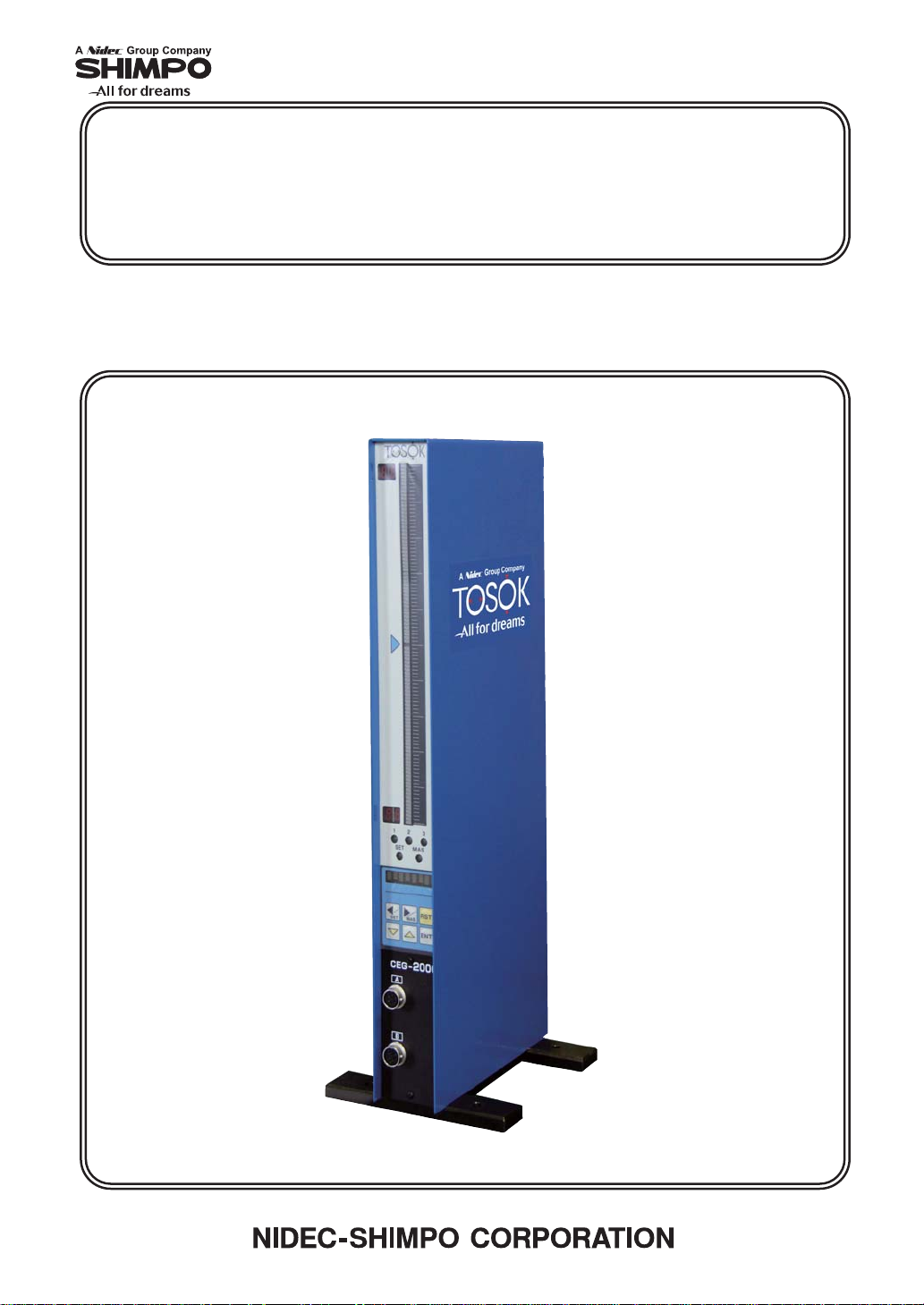
1 Overview
Our columnar electronic micrometer features color bars of three different colors, which makes
the display easy to see. The meter also features an automatic master matching function.
It can be used by itself or can easily be deployed in complex combinations with other
components. With the bar displays arrayed next to each other, the property of the object being
measured can be ascertained.
2 Features
(1) Displays measurement results clearly using a three-color color bar display.
(2) With an eight-digit display, it can display such information as measured values and setting
names.
(3) Master alignment for both large and small limits can be accomplished at the push of a
button.
(4) Because the instrument is only 50mm wide, it can be used in a series configuration.
(5) With the serial communications function (included standard), data can be output to a PC and
printer. The data can be saved and input into statistical and spreadsheet applications (such as
Microsoft Excel).
(6) In the Set-up Mode, all settings can be entered in order by pressing the ENT key.
(7) Up to 10 different sets of settings and master values can be saved and selected from.
3Operation
This instrument has the following four principal modes of operation:
(1) Measurement mode
• Measurement mode Measures
• Hold measurement Saves the measured values
However, if master matching was unsuccessful, the values are
not saved.
(2) Set-up Mode
• Set-up Mode Inputs or changes settings.
(3) Master matching mode
• Master matching Matches with a master.
This instrument conducts comparative measurements, so only
use it after having measured a master for comparison.
• Adjust detector (ADJ) This will adjust the detector.
• Clear master match This will clear master match data.
(4) Program switching mode
• Program switching mode Switches programs.
The instrument launches with the last program that was used
before it was last shut down.
-1-
Page 5
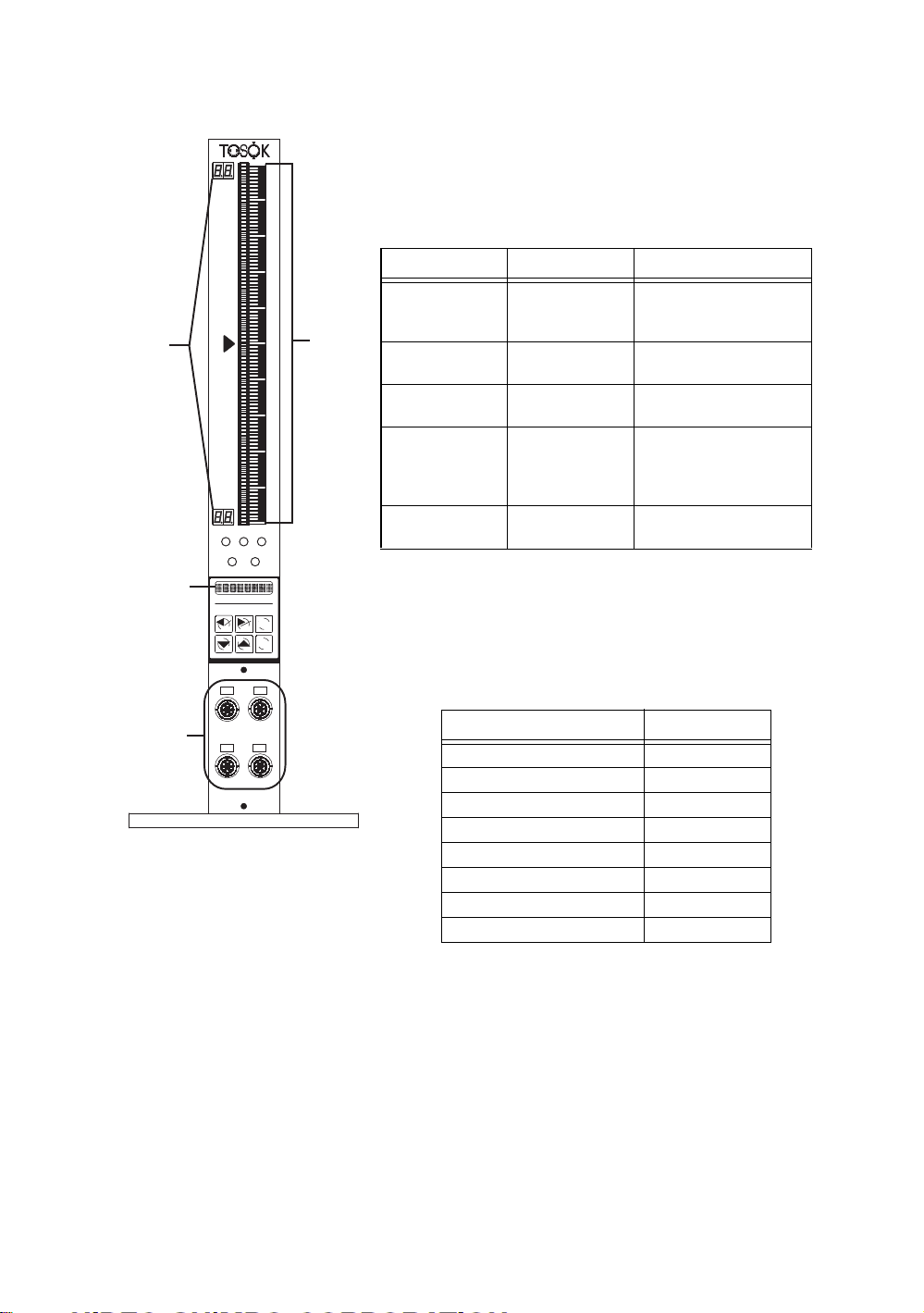
4 Names and functions of the parts
[1] Bar graph display
Displays a 101-dot, three-color bar graph.
Table 1: Bar color and information displayed in each
mode
Mode Bar color Information displayed
[2]
[3]
123
SET
MAS
RST
MAS
SET
ENT
[1]
Measurement Green (bright)
Hold
measurement
Setting Orange (bright)
Master matching Green (bright)
ADJ Orange (bright)
[2] Range display
The upper and lower measurements of the bar are given
with a two-digit display. The display is the same for
items 1-3 as shown in Table 2 below.
Red (bright)
Orange (dotted)
Green (dark)
Red (dark)
Green (dotted)
Red (bright)
Orange (dotted)
Green (dotted)
Value measured was OK.
Value measured not OK.
Upper or lower limit value.
Value measured was OK.
Value measured not OK.
Current setting value
Previous setting value
Master matching possible
Master matching not
possible
Master setting value
Value measured
Master setting value
[4]
C
A
D
B
Table 2: Range display
Measured range (microns) Digital display
52.5
10 5.0
20 10.
50 25.
100 50.
200 10
500 25
1000 50
[3] Display
A 7 × 5 dot character, eight-digit display can show
measured values, set values, setting names, and other
information.
[4] Measurement device ports
Measurement devices can be connected as follows: A
and B for two-channel type devices, and A-D for fourchannel type devices.
-2-
Page 6
123
MAS
SET
SET MAS
RST
ENT
[5]
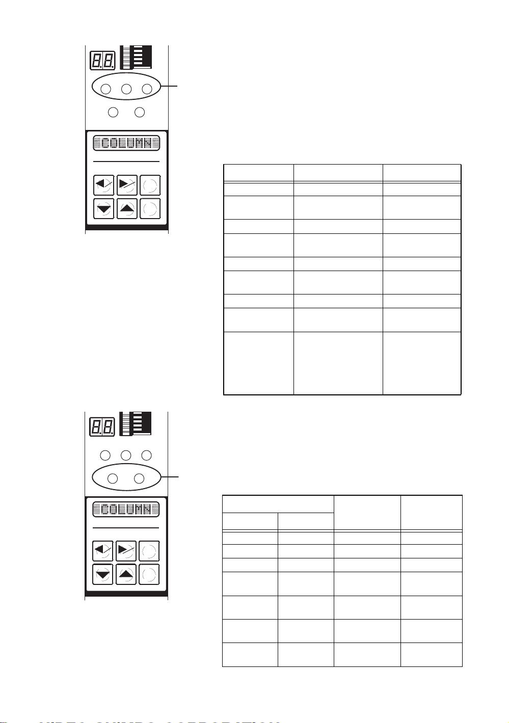
[5] Item/decision lamps
This shows information such as the decision made and
whether a measurement is currently being taken
(whether the bar is being displayed).
Each number, 1-3 shows the status for the corresponding
item (3 is for the calculated result).
Table 3 shows the relationship between lamp colors and
status.
Table 3: Lamp colors and status
Lamp color Status Mode
Green (bright) Decision: OK Measurement
Green
(bright and dark)
Green (dark) Decision: OK Hold measurement
Green (dark) and
black
Red (bright) Decision: NG Measurement
Red
(bright and dark)
Red (dark) Decision: NG Hold measurement
Red (dark) and
black
Orange (bright) Item-related settings
Decision: OK
(bar being displayed)
Decision: OK
(bar being displayed)
Decision: NG
(bar being displayed)
Decision: NG
(bar being displayed)
being input
Master matching
(Item 3 excluded)
Sensor being adjusted
(Item 3 excluded)
Measurement
Hold measurement
Measurement
Hold measurement
Setting
Master matching
ADJ
123
SET MAS
SET MAS
RST
ENT
[6]
[6] Mode lamps
These show the current mode and master matching
status.
Table 4 shows the relationship between lamp color,
mode and master matching status.
Table 4: Colors and status
Lamp name
SET MAS
Orange (bright) — Setting —
Green (bright) — Program switching —
— Orange (bright) Master matching —
Orange (bright) Red (bright) Setting Master matching
Green (bright) Red (bright) Program switching Master matching
— Orange (bright)
& Red (bright)
— Red (bright) Measurement
Mode
Master matching Master matching
Hold measurement
Master
matching status
unsuccessful
unsuccessful
unsuccessful
Master matching
unsuccessful
-3-
Page 7
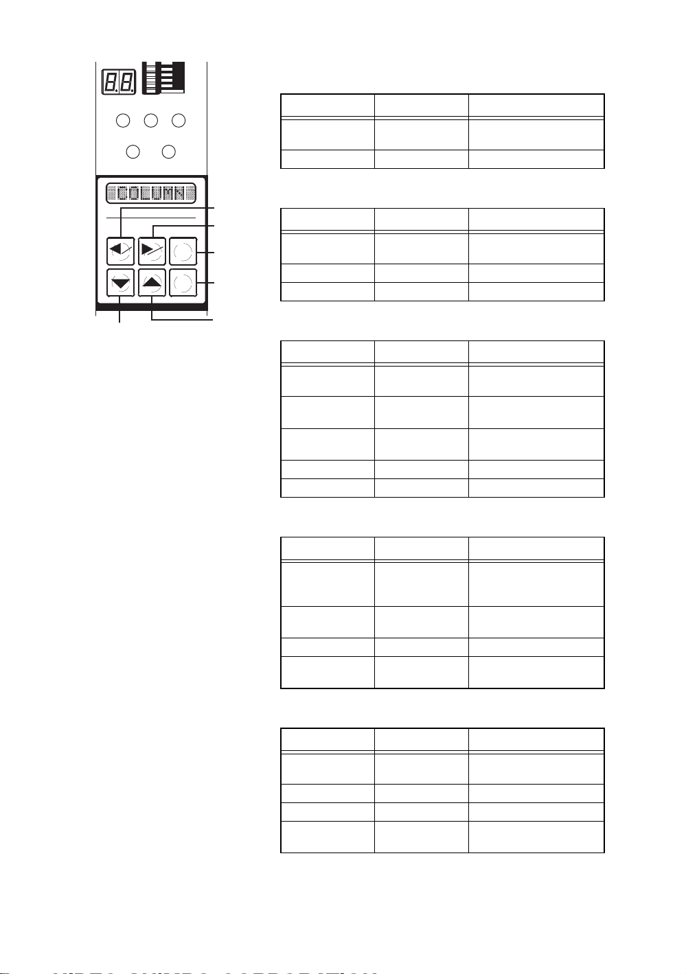
[7] Panel switches
(a) Left arrow key (SET key)
123
SET MAS
SET MAS
RST
ENT
(f)
(a)
(b)
(c)
(d)
(e)
Mode Key action Status
Measurement Hold down for two
seconds
Setting Press once Select setting parameter
Switches to master matching
(b) Right arrow key (MAS key)
Mode Key action Status
Measurement Hold down for two
seconds
Setting Press once Select setting parameter
Master matching Press once Switch displayed information
Switches to master matching
(c) Reset key
Mode Key action Status
Hold setting value Press once Switches to measurement
Setting (settings
being input)
Setting (item being
selected)
Master matching Press once Returns to previous display
ADJ Press once Returns to previous display
Press once Returns settings to their
Press once Cancel settings (Write/
mode
previous values
Cancel)
(d) ENTER key
Mode Key action Status
Measurement Press once Holds the measured values
Setting Press once Decide setting item and
Master matching Press once Read in master values
ADJ Press once Decide adjustment item and
(If master matching was
successful)
setting value
adjustment value
(e) Up arrow key
Mode Key action Status
Measurement Press once Switch which information is
Setting Press once Enter setting values
Master matching Press once Switch display masters
ADJ Press once Switch detector that is
displayed
displayed
-4-
Page 8
(f) Down arrow key
Mode Key action Status
Measurement Hold down for two
seconds
Measurement Press once Switch which information is
Setting Press once Enter setting values
Master matching Press once Switch display masters
ADJ Press once Switch detector that is
Switch to program switching
mode
displayed
displayed
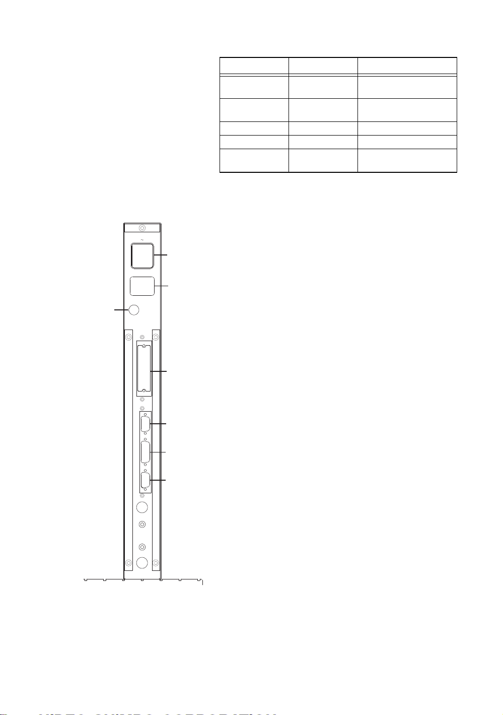
[10]
Back
AC85 264V
FUSE
EXT I/O
RS232C
SW,ETC
ANALOG
[8] Input power connector/power switch
This turns on the AC power. Although the instrument
can be used within the 85-264V AC range, the included
power cable can only be used in the 85-125V AC range.
[8]
[9] Output power connector
When used in a series configuration, this connects to the
[9]
input power connector of the neighboring unit. It
connects to the input power connector internally.
3A
[10] Fuse holder
Glass tube fuses (5.2 × 20 3A) are used.
[11] DC input and output connectors (optional)
[11]
This is a connector for decision/ BCD output for
connection to lamps, sequences, etc.
[12] RS232C connectors
This is a serial connector for use in linking to PCs and
[12]
[13]
printers.
[13] Switch input connector
This connector enables measurement commands and
master commands to be given by means of an external
[14]
push button. This can also be used for RS422
communication and Digimatic output (optional).
[14] Analog input/output connector
This connector is for input of external analog signals and
output of amp output signals.
-5-
Page 9
5 Specifications
Item Specification Comments
Input Electrically, 2 (4) channels
Measurement item 3 (Calculation 1)
Calculation method 1–2, 1+2, 2–1, AVE (1–2), AVE (1+2), AVE (2–1) 1=ITEM 1 2=ITEM 2
Measurement range
(mm)
Resolution (mm) 0.00005 0.0001 0.0002 0.0005
Bar display 101-dot (red, green, orange, bright/dark)
Bar display type Bar (OK: Green, Not OK: Red), Dots (Max./Min.)
Scale display Two-digit (numbers), two locations
Multi-function display Eight-digit (Numbers/letters)
Shift range ±300% (Full scale)
Decision ± Not OK/OK
Display of decision Bar display (color), items, decision lamp, multi-
Automatic master
matching
Automatic master range Small: ±50% (full scale)
Program entry Push-button on panel
Number of set programs 10
Power voltage and
frequency
Power capacity 30VA
Dimensions/weight 50mm (width) × 480mm (height) ×
Operating temperature 0-45°C
Standard
External input buttons 4 (measurement, reset, large limit, small limit) Push-button, Foot SW
Serial output 1 (printer, PC) RS232C
Options
Printer output 1 (DP1) Digimatic
Decision output 8 (DC12/24V)
BCD output 1 set (DC12/24V)
Analog input 4 (connection to column)
Serial communication 1 RS422/RS485
0.00500 0.0100 0.0200 0.0500
0.100 0.200 0.500 1.00
0.001 0.002 0.005 0.01
Measured values, setting items, setting values,
error messages
function display
Small limit, large limit
Large: ±20% (full scale)
85-256V AC 50/60Hz Comes with 100V AC
200mm (depth), 4 kg
cable
-6-
Page 10

6Operation
6.1 Overview
• What to do when the detector has been connected and adjusted and the settings have
already been entered.
• What to do when the measurement head has been replaced
In this section, we will explain the procedures for the above two situations.
6.1.1 What to do when the detector has been connected and adjusted and
the settings have already been entered.
Please use the following procedure.
(1) Power on
Turn on the power switch in the rear of the unit (press the side marked with a circle)
to supply power (85-265V AC and 50/60Hz). The unit will start up in Measurement
Mode.
In Measurement Mode, hold down the right arrow (MAS) key for two seconds.
Holding the key down for an additional two seconds switches to Clear Master Match.
(2) Clearing the master matching data
Clear the master matching data as necessary. For details, refer to 6.4.3 “Clearing the
Master Match.”
(3) Master matching
Now match to a master. For details, refer to 6.4.1 “Master matching.”
(4) Measuring
In Measurement Mode, press the ENT key once, the unit will be set to Hold
Measurement Value. This can be cleared by pressing the RST key. However, if the
master match was unsuccessful, the measured value cannot be saved. For details,
please refer to 6.2 “Measuring.”
-7-
Page 11

6.1.2 What to do when the measurement head has been replaced
Please use the following procedure.
(1) Connection
Connect the detectors to the front of the column unit and the included power cord to
the back.
(2) Power on
Turn on the power switch in the rear of the unit (press the side marked with a circle)
to supply power (85-265V AC and 50/60Hz). The unit will start up in Measurement
Mode.
In Measurement Mode, hold down the left arrow (SET) key for two seconds, which
will switch to Set-up Mode.
(3) Inputting setting values
Please input the setting values. For details, please refer to 6.3 “Set-up mode.”
In Measurement Mode, hold down the right arrow (MAS) key for two seconds. After
that, pressing the key down once switches to Adjust Detector (ADJ).
(4) Adjust Detector
Please adjust the detector. For details, refer to 6.4.2 “Adjusting the detector.”
In “Adjust Detector” mode, holding down the ENT key for two seconds switches to
Master Matching.
(5) Master matching
Please match to a master. For details, refer to 6.4.1 “Master matching.”
(6) Measuring
In Measurement Mode, pushing the ENT key once switches to Hold Measured
Values. This can be cleared by pressing the RST key. However, if the master match
was unsuccessful, the measured values cannot be saved. For details, please refer to
6.2 “Measuring.”
-8-
Page 12

6.2 Measuring
123
SET MAS
6.2.1 Measurement mode
• Items currently being shown in the bar display are indicated by the blinking (light
and dark) of “Item/decision lamps 1, 2, and 3.” For details on the colors of the
lamps, refer to 4. [5] “Item/decision lamps.”
• The up and down arrow keys can be used to toggle between bar display items.
6.2.2 Hold measured value
• In Measurement Mode, pressing the ENT key will hold the measured value (will
enter a holding state). However, if master matching was unsuccessful, the
measurements will not be held.
• For the item shown in the bar display, the Item/decision lamps will blink (light and
blank). For details on the colors of the lamps, refer to 4.[5] “Item/decision lamps.”
• The up and down arrow keys can be used to toggle between bar display items.
• Pressing RST (reset) releases the hold.
SET MAS
RST
ENT
-9-
Page 13

6.3 Set-up mode
Set-up must be performed for each program used. After changing the program number,
please perform set-up.
6.3.1 Selecting the measurement range
1) In Set-up Mode, hold down the left arrow key for at least two seconds.
2) The orange “SET” LED will light up, “RANGE” will be displayed and the
system will be in Set-up Mode.
3) Push the ENT key once.
4) The current measurement range will be displayed.
5) Press the up and down arrow keys to select a measurement range (5, 10, 20, 50,
100, 200, 500, and 1000 microns).
6) After making a selection, press the ENT key.
7) After measurement range selection has been completed, next is the set-up of the
shift value. “SHIFT” will now be displayed.
6.3.2 Setting the shift value
For one-sided tolerances and such, the bar display will move to the center. Set this
function to 0 to make it inactive.
1) With “SHIFT” displayed, press the ENT key.
2) The current shift value will be diaplayed.
3) Use the up and down arrow keys to enter the new shift value.
4) After entering the shift value, press the ENT key.
5) After the shift value is set, next will come selection for mask matching. “MAS
SET” will be displayed.
6.3.3 Selection for mask matching
1) With “MAS SET” displayed, press the ENT key.
2) The current mask matching setting value will be displayed.
3) Use the up and down arrow keys to select either “ALL” or “EACH.”
4) When carrying out mask matching:
“ALL” . . . . . . Mask matching is performed all at once.
“EACH” . . . .Mask matches are performed one by one.
5) After selecting the mask match settings, press the ENT key.
6) After mask matching set-up is complete, next will come polarity selection for
each measuring unit. “XDUCER” will be displayed.
-10-
Page 14

6.3.4 Polarity selection for each measuring unit
1) With “XDUCER” displayed, press the ENT key, and perform the set-up of each
measuring unit.
2) Use the up and down arrow keys to toggle between measuring units A-D and
“FINISH” as shown on the display. Select the name of the measuring unit to
change the settings for and press the ENT key.
• Select a letter A-D . . . to change the settings for a particular measuring unit.
• Select “FINISH”. . . . . to quit the set-up process.
Go to selections in “6.3.5 Item selection.”
3) With “POL” displayed, press the ENT key. Set the polarities for each measuring
unit.
4) Use the up and down arrow keys to select “+” or “–”, and then press the ENT
key.
Internal diameter measurement
Direct Direct
Measuring methodSelection of POL
Using levers
5) Return to step 2) above.
6.3.5 Selection of items
1) With “ITEM” and the eight-digit display visible, press the ENT key. Then, enter
the settings for each item.
2) Use the up and down arrow keys to toggle between item numbers 1-3 and
“FINISH” as shown on the display. Select the name of the item to change the
settings for.
PG Type
External diameter measurement Height
OG Type
Using levers
measurement
+ ++
3) Select the name of the item to change the settings for and press the ENT key.
Select item 1 or 2 6.3.6 Input channel selection
Select item 3
Select finish 6.3.12 Save setting values
6.3.11 Selecting the calculation
method
-11-
Page 15

6.3.6 Input channel selection (In items 1 and 2)
1) With “INPUT” and the eight-digit display visible, press the ENT key. Next,
select an input channel.
2) The current input channel will be displayed. Use the up and down arrow keys to
select an input channel.
3) Select the input channel and press the ENT key.
None 6.3.5 Item selection
Other
6.3.7 Setting the decision upper
limit value
6.3.7 Setting the decision upper limit value (Set for all items)
1) With “MAX” displayed, press the ENT key.
2) “Current decision upper limit value” will be displayed.
3) Use the up and down arrow keys to input the new decision upper limit value.
4) After selecting the decision upper limit value, press the ENT key.
5) After decision upper limit value has been set, next will come selection of the
decision lower limit value. “MIN” will be displayed.
6.3.8 Setting the decision lower limit value (Set for all items)
1) With “MIN” displayed, press the ENT key.
2) The current decision lower limit value will be displayed.
3) Use the up and down arrow keys to input the new decision lower limit value.
4) After selecting the decision lower limit value, press the ENT key.
Item being set in
items 1 and 2
6.3.9 Setting the large master value
Item being set in
item 3
6.3.5 Item selection
2) To state in which FINISH is
selected.
-12-
Page 16

6.3.9 Setting the large master value (Set in items 1 and 2)
1) With “MAX M.” displayed, press the ENT key.
2) The current large master value will be displayed.
3) Use the up and down arrow keys to input the new large master value.
4) After inputting the large master limit, press the ENT key.
5) The eight-digit display will be shown.
MIN M.
ERR MAS
6.3.10 Setting the small master
value
The value will return to what it was
before it was changed and the
display will be as in 2) above.
An error will be displayed if the
large master value is equal to or
less than the small master value.
6.3.10 Setting the small master value (Set in items 1 and 2)
1) With “MIN M.” displayed, press the ENT key.
2) The current small master value will be displayed.
3) Use the up and down arrow keys to input the new small master value.
4) After inputting the small master limit, press the ENT key.
5) The eight-digit display will be shown.
Item 1, Item 2
Item 3, Item 4
Switches to the same state as in
2) in 6.3.5 Item Selection
ERR MAS
The value will return to what it was
before it was changed and the
display will be as in 2) above.
An error will be displayed if the
small master value is equal to or
greater than the small master value.
-13-
Page 17

6.3.11 Selecting the calculation method (in Item 3 only)
1) With “CALC” displayed, press the ENT key.
2)
The current calculation expression will be displayed.
! NOTE In the calculation method display, “1” shows Item 1 and “2” shows
Item 2.
3) Use the up and down arrow keys to either select a calculation method, or select
“Use none.”
4) After selecting the calculation method, press the ENT key.
5) The eight-digit display will be shown.
FINISH
MAX
Switches to the same state as in
B in 6.3.5 Item Selection
Switches to 6.3.7 Setting the
decision upper limit value
6.3.12 Saving setting values (Saving the previous items 6.3.1-11)
If you quit while still inputting settings, “END” can be displayed by pressing both
reset and the left and right arrow keys.
1) With “END” displayed, press the ENT key.
2) “WRITE” will be displayed.
3) Use the up and down arrow keys to either select either “WRITE” or
“CANCEL.”
4) After making this selection, press the ENT key.
5) Quit Set-up Mode and return to Measurement Mode.
Selection items in
WRITE
Selection items in
CANCEL
Save the new settings.
Erase the new settings and revert
to the previous settings.
-14-
Page 18

6.4 Master Matching Mode
6.4.1 Master matching
23
1
SET MAS
SET
MAS
23
1
SET MAS
SET
MAS
RST
ENT
RST
ENT
1)
4)
2)
5)
1) In Set-up Mode, hold down the right arrow (MAS)
key for at least two seconds.
2) The “MAS” LED (orange) will light up and “MIN
M.” will be displayed, switching to “Master
Matching.”
3) When “ALL” is selected under “Master Match
Selection (MAS SET)” in Setting Mode, master
matching will be done all at once. If “EACH” is
selected, master matching will be performed one at
a time.
4) When master matching is performed one at a time,
master matching is performed for the item currently
shown in the bar display. Use the up and down
arrow keys to toggle between the items that master
matching will be performed on. The Item/Decision
Lamps show which item is currently shown in the
bar display.
When “1” is lit, it means that Item 1 is displayed.
When “2” is lit, it means that Item 2 is displayed.
5) Set the small master to a detector, and when the bar
display stabilizes, press the ENT key.
-15-
Page 19

1
23
6) Small master matching will be performed, and
“MAX M.” will be displayed.
SET MAS
SET
MAS
RST
ENT
6)
7)
7) Set the large master to a detector, and when the bar
display stabilizes, press the ENT key.
8) Large master matching will be performed.
If there are no errors....... To 9)
If there is an error........... To 10)
9) “MAS OK” will be shown in the eight-digit display
for two seconds, after which Master Matching will
be concluded and the unit will return to
Measurement Mode.
10) The following error messages may appear in the
eight-digit display.
“ERR ZERO”. . . A “zero” error (outside the
master matching range)
“ERR MAG” . . . A “sensitivity” error (outside the
master matching range)
“ERR REV” . . . . A MAX/MIN reversal
“ERR OFFR” . . . Out of measurable range
Press the ENT key to return to B above.
If the detector requires adjustment, press the right
arrow key and proceed to adjust the detector.
11) If master matching is being performed one at a
time, and master matching is OK for both items, the
unit will switch to a new master matching channel
and return to B above.
12) If the RST key is pressed during master matching,
the unit will return to its previous state. If “MIN
M.” was displayed, it will return to Measurement
Mode.
-16-
Page 20

6.4.2 Adjusting the detectors
No adjustment is required except after the measurement head is replaced.
1) ZERO ADJ (zero adjustment)
In the following procedure, the small master is used to match the small master
value and the bar display position.
(a) In Measurement Mode, hold down the right arrow (MAS) key for at least
two seconds.
(b) The “MAS” LED (orange) will light up, “MIN M.” will be displayed, and
the unit will switch to Master Matching Mode.
(c) Press the right arrow button.
(d) The unit will switch to Detector Adjustment Mode and “ADJ” will be
displayed.
(e) Use the up and down arrow keys to switch to the item to be adjusted (Item
1 or 2). The item currently shown in the bar display is indicated on the
Item/Decision Lamps. In addition, the Detector Name for the measuring
unit the item is using for measurement is shown in the eight-digit display.
(f) Press the ENT key.
(g) “ZERO ADJ” will be displayed.
(h) Press the ENT key.
(i) The name of the measurement unit that the item selected in (e) uses, as well
as its current ZERO ADJ setting will be displayed.
(j) If the ZERO ADJ setting is not displayed, it is because the item selected in
E has data for two measurement units. Use the left and right arrow keys to
toggle between the ZERO ADJ settings for the two units.
(k) Set to small master and use the up and down arrow keys to adjust each
measurement units ZERO ADJ setting so that the item’s data approaches
the small master setting.
(l) After setting is compete, press the ENT key.
(m) “GAIN ADJ” will be shown in the eight-digit display. Proceed to set the
GAIN ADJ setting.
-17-
Page 21

2) GAIN ADJ (sensitivity adjustment)
In the following procedure, both small and large masters are used to match the
small and large master values with the bar display range.
(a) With “GAIN ADJ” displayed, press the ENT key once.
(b) The measuring unit that the item selected in 6.4.2 1) (e) uses, as well as the
current GAIN ADJ setting value, will be shown in the eight-digit display.
(c) If the GAIN ADJ setting value is not shown, it means that the item selected
in 6.4.2 1) (e) has data for two measuring units. Use the right and left arrow
keys to toggle between the data for these two measuring units.
(d) Alternately set the small master and the large master, and use the up and
down arrow keys to adjust each item's measurement unit GAIN ADJ
setting so that it approaches the small master setting and the large master
setting.
(e) After these settings are complete, press the ENT key.
(f) “MAG ADJ” will be displayed. That concludes the GAIN ADJ setting
input procedure.
(g) Proceed to input settings for MAG ADJ.
3) MAG ADJ (fine sensitivity adjustment)
The following procedure is used to set the coefficient for each item when one
item has two measuring units. This should be set to 1,000 for most purposes.
(a) With “MAG ADJ” displayed, press the ENT key once.
(b) The name of the measuring unit that the item selected in 6.4.2 1) (e) uses
will be shown in the eight-digit display, along with its current MAG ADJ
setting.
(c) If the MAG ADJ setting is not displayed, it is because the item selected in
6.4.2 1) (e) has data for two measuring units. Use the left and right arrow
keys toggle between the data for each one.
(d) Use the up and down arrow keys set the GAIN ADJ for each measuring
unit.
(e) After these settings are complete, press ENT.
(f) “MIN M.” will be displayed and the unit will switch to 6.4.1 “Master
Matching.” This concludes the MAG ADJ setting procedure.
-18-
Page 22

6.4.3 Clearing the master match
23
1
SET MAS
SET
MAS
2
1
SET MAS
SET
MAS
RST
ENT
3
RST
ENT
1)
2)
3)
1) In Measuring Mode, hold down the right arrow
(MAS) key for at least two seconds.
2) The “MAS” LED (orange) will light up, “MIN M.”
will be displayed, and the unit will switch to Master
Matching Mode.
3) Press the right arrow key once.
23
1
SET MAS
SET
MAS
23
1
SET MAS
SET
MAS
RST
ENT
RST
ENT
4)
5)
6)
7)
4) This will switch to Detector Adjustment, and
“ADJ” will be displayed.
5) Press the right arrow key once.
6) This will switch to Clear Master Match, and
“MAST CLS” will be displayed.
7) Pressing the ENT key will clear all master matching
data, “M.CLS OK” will be displayed and the unit
will return to 6.4.1 “Master Matching.”
-19-
Page 23

6.5 Program Switching Mode
23
1
SET MAS
SET
MAS
1)
2
1
SET MAS
SET
MAS
RST
ENT
3
RST
ENT
2)
3)
(1) In Measurement Mode, hold down the down arrow
key for at least two seconds.
(2) The “SET” LED (green) will light up, “PROG” will
be displayed, and the unit will enter Program
Switching Mode.
(3) Press the ENT key.
23
1
SET MAS
SET
MAS
5)
RST
ENT
4)
6)
(4) The program that is currently in use is indicated by
a number 0-9.
(5) Using the up and down arrow keys, select the
number of the program number to be used.
(6) After making a selection, press the ENT key.
(7) This will quit Program Switching Mode and return
to Measurement Mode.
(8) After a new program number has been selected, it
may be necessary to perform master matching. If a
measuring device has been replaced, it may be
necessary to adjust the detector.
(9) In order to perform set-up, first switch to the new
program number and then enter Set-up Mode.
(10) When power is turned on, the most recently
selected program is launched.
-20-
Page 24

7 An explanation of input and output
7.1 Serial output (RS232C)
7.1.1 Overview
Through the RS232C, this unit is capable of outputting measured values to a printer
or sending the data to a PC. The following information can be sent to a PC:
(1) Measurement items Items 1-3
(2) Measured values The data shown in the unit's eight-digit display, Use None
(3) Decision +Not OK, OK, –Not OK, NJG (only with “Use None”)
7.1.2 Preparation
This units RS232C port enables it to output data. Please connect the optional Dsub9C (male) communications cable to this unit’s RS232C port. Three different
optional communications cables are available for different applications. For details,
please refer to 9. “Options.”
7.1.3 Serial port settings
Baud rate 9,600
Bits/text 8
Stop bit 1
Start bit 1
Parity bit None
7.1.4 Composition of transmitted data
Item 1 (five digits), space (one digit), measured value (eight digits), space (one digit),
decision (three digits), space (one digit).
Item 2 (five digits), space (one digit), measured value (eight digits), space (one digit),
decision (three digits), space (one digit).
Item 3 (five digits), space (one digit), measured value (eight digits), space (one digit),
decision (three digits), CR, LF.
ITEM1
ITEM2
ITEM3 CRLF
7.1.5 Method of data transmission to PCs
In Measurement Mode, press the ENT key. This will switch to the Hold Measured
Value Mode described in 6.2.2, and will transmit the measured value. If the master
match was unsuccessful data will not be transmitted.
Measured value
Measured value
Measured value
Decision
Decision
Decision
-21-
Page 25

7.1.6 Requesting data from PCs
(1) Latch (data hold) command for the measured value
Send command byte “E” (45H). This micrometer will hold the measured value.
(2) Latch release command
Send command byte “R” (52H). This micrometer will release its hold on the
measured value.
(3) Request for measured value
Send command byte “D” (44H). This micrometer will send the data in 4 above
to the PC.
7.1.7 Examples
Text
ASCII cord
ITEM1
ITEM2
ITEM3 CRLF
49
54 45 4D 31
49 54 45 4D 32
49 54 45 4D 33 0D
N
202020
0.52
5.21
ESUO
G47N
K47O
G47J4AN
20
4E2D20302E35322D20
20
4F2020352E32312020202020
4E20455355204F4E202020
0A
-22-
Page 26

7.2 Input from an external button
7.2.1 Overview
With this unit, the following can be done from external buttons.
(1) Measuring
(2) Resetting
(3) Large master matching
(4) Small master matching
7.2.2 Preparation
SW, ETC port on the back of the unit is the port for external buttons. The D-sub 15P
(male) cable can be connected to this unit’s SW, ETC port.
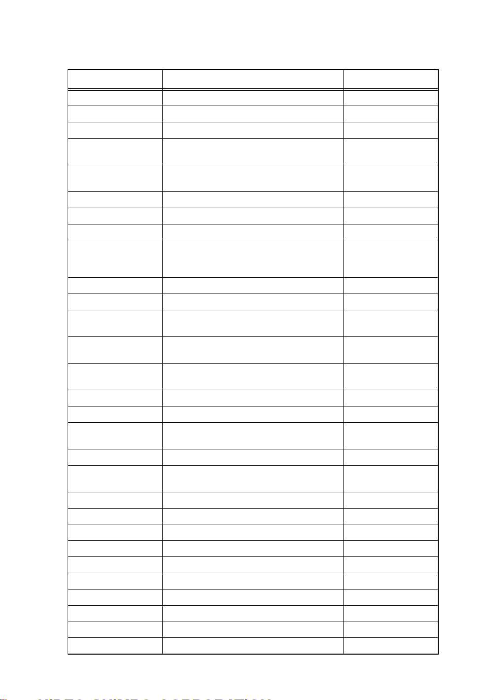
7.2.3 The port’s pin layout
Description
GND
Measure button
Reset button
No.
1
2
3
4
5
6
7
8
The pin layout of the SW, ETC port on the back of this unit.
7.2.4 Operation with external buttons
(1) Measure button
(a) In Measurement Mode, press the Measure button.
(b) This will hold the measured value..
! NOTE If master matching was unsuccessful, this data cannot be held.
(2) Reset button
This releases the hold.
(3) Large Master Matching button
(a) In large master matching waiting status, set the large master to the detector.
(b) After the bar display stabilizes, press the Large Master Matching button.
(c) The unit will carry out large master matching and return to Measurement
Mode.
(d) If there is a master matching error (see 6.4.1 10)), please cope with it using
this unit’s panel switches.
(4) Small Master Matching button
(a) In Measurement Mode, set the small master to the detector.
(b) After the bar display stabilizes, press the Small Master Matching button.
(c) The unit will carry out small master matching and return to large master
matching status.
No.
Large master button
9
Small master button
10
11
12
13
14
15
Description
! NOTE In Set-up Mode, please choose ALL from the Selection for mask
matching (refer to 6.3.3).
-23-
Page 27

8 Models
CEG 20 00 -2 -DP
9 Options
9.1 Main unit
(1) Digimatic output Printer (DP1), etc.
(2) Decision output 24V DC
(3) BCD output 24V DC
9.2 Sold separately
(1) Communications cable (CAG2000-OP-CB-1)
(2) Communications cable (CAG2000-OP-CB-2)
(3) Communications cable (CAG2000-OP-CB-3)
External input
and output
Input
Model number
Basic model
number
D-sub 9-pin port for PCs (EIA-232))
D-sub 25-pin port for PCs (EIA-574))
D-sub 25-pin port for PCs (EIA-574))
None: Standard
DP: Digimatic output
DC: Decision output
BC: BCD output
2: Two-channel
4: Four-channel
20
CEG
10 Maintenance
(1) Use alcohol to clean dirt off of the main unit.
The use of thinner causes color loss and dullness.
-24-
Page 28

11 Breakdowns: Causes and Responses
Symptom
Repeat precision is
unstable
The bar graph
display does not
move
The bar graph and
digital display are
blinking.
Location of breakdown or
maladjustment
Movement of the part that secures the
measuring unit
1) The proper amount of power is not
being supplied.
2) The detector is maladjusted.
3) The unit is in Hold Measurement
Mode (the bar graph is green or dark
red).
4) The unit is in Set-up Mode (orange).
1) Power is not being supplied.
2) A fuse has blown.
3) The power supply or an internal
circuit has failed.
12 Points of Caution
(1) Electrical wiring
The power cable included standard with this unit is 100V. To use the unit with voltage that
exceeds 125V, please use the 250V power cable.
(2) Do not use a hard tool, something sharp, to press the operation keys.
(3) About exporting these units
Export of this product may fall under the Export Control Directive, and may therefor require
the permission of the Ministry of Trade and Industry. Please discuss this with a
representative at our nearest sales office.
(4) Other
This product’s specifications may be changed without prior notice.
Response
Tighten the loose part.
1) Supply power in the 85-264V range.
2) Adjust the detector.
3) Release using the RST (reset) key.
4) Quit Set-up Mode.
1) Supply power in the 85-264V range.
2) Replace the fuse (3A).
3) Request service from the
manufacturer.
-25-
Page 29

13 Structural diagrams of the main unit
Structural diagram of the (two-channel) Columnar Electronic Gage
! NOTE An asterisk indicates an option.
Front Back
LED digital range
display (two)
AC85~264V
Power switch
Power port (input)
Power port (output)
LED bar graph
display
Item/Decision lamp
(three)
Mode lamp (two)
Display
Panel switches (six)
Fuse holder
FUSE
3A
DC output port *
EXT I/O
RS232C port
1
32
SET
MAS
RST
MAS
SET
ENT
RS232CSW. EJCANALOG
Switch input port
Analog input and
output port
Detector port
[A]
[B]
-26-
Page 30

Structural diagram of the (four-channel) Columnar Electronic Gage
! NOTE An asterisk indicates an option.
Front Back
LED digital range
display (two)
AC85~264V
Power switch
Power port (input)
Power port (output)
LED bar graph
display
Item/Decision lamp
(three)
Mode lamp (two)
Display
Panel switches (six)
12
MAS
SET
MAS
SET
RST
ENT
Fuse holder
FUSE
3A
DC output port *
EXT I/ORS232CSW. ETCANALOG
RS232C port
3
Switch input port
Analog input and
output port
Detector port
[A] [C]
[B] [D]
-27-
Page 31

Clear master data
M. CLS OK
MAST CLS
See Master Matching Mode (Ref. 2).
R
(eight-digit and bar displays)
Raw data display
Detector Adjustment Master Data Clear
28
RUN
OK
MAS1 OK?
Error present
E
E
Error present
E
E E
detected
Error
M A X M.
R
M I N M.
R
RUN
OK
MAS2 OK?
detected
Error
M A X M.
R
MIN M. ADJ.
R
NO
MAS OK display
Error absent
to MAS1.
3.
3. Use the and keys to switch
MAS 2
NO
MAS OK display
Error absent
to MAS2.
*2 *2
2.
2. Use the and keys to switch
MAS 1
E
Error display
R
E
Error display
R
Error display
Error present
E
E
RUN
detected
Error
MAS OK display
Error absent
M A X M.
1.
R
*1 *1
M I N M.
1.
R
ALL
EACH
MAS SET
through the items in the display.
1. Use the and keys to toggle
See Master Matching Mode (Ref. 1).
becomes invalid.
changed, the master matching data
When the program number is
Select ten items.
RUN
E
0
9
R E
PROG
Switch programs
Clear master data
M. CLS OK
E
MAST CLS
See Master Matching Mode (Ref. 2).
R
R
ADJ.
(eight-digit and bar displays)
Raw data display
Detector Adjustment Master Data Clear
Error items are shown on the lamp display.
E
Set-up Mode
seconds.
cannot be held.
unsuccessful, the measured value
When master matching is
ITEM 1
ITEM 2
ITEM 3
Toggle displayed item
R
Hold measured value
E
for two seconds.
Press and hold key
ITEM 1
ITEM 2
ITEM 3
RUN
for two
hold key
Press and
Toggle displayed item
Measurement Mode
for two seconds.
Press and hold key
Standard software (for Electronic Micrometer) Ver2.11
14 Operational flow
Page 32

Standard software (for Electronic Micrometer) Ver2.11
Master Matching Mode (Ref. 2)
ADJ.
[A]
[B]
[C]
[D]
[A+B]
[C+D]
E
R
*2
ZERO ADJ
E
R
127
*1 *1 *1
-128
E
GAIN ADJ
R
[A] [D]
R
MAG ADJ
E
255
0
E
R
[A] [D][A] [D]
MIN M.
R
E
1. 300
0. 700
E
Note
* 1) Use the left and right arrow keys to select the measuring device to change the settings for,
and use the up and down arrow keys to change the settings.
*2
-29-
Page 33

Standard software (for Electronic Micrometer) Ver2.11
E
CANCEL
WRITE
Setup Mode (Ref. 1)
R
R
R
R
E
END
R R
E
ITEM
E
XDUCER
R
E
MAS SET
R
CANCEL
WRITE
OPTION
of options.
Used with purchase
[A]
[D]
FINISH
ALL
EACH
E
[A]
E
E
RUN
[B]
[C]
Select 2 item. Select 2 item. Select 2 item.
[D]
Setup Mode (Ref. 2)
R
E
POL
R
E
Select 2 item.
FINISH
Set-up is required for each program that is to be
used. After changing the program number,
please go through the set-up procedure.
Press and hold key for two seconds.
R R
RANGE SHIFT
Measurement Mode
*1 *1
E
R
E
1000
R
+ 0.0
500
200
100
E
502010
Driver set-up
5
E
Select 8 item.
-30-
Page 34

Standard software (for Electronic Micrometer) Ver2.11
Setup Mode (Ref. 2)
ITEM
E
R
FINISH
ITEM 3
ITEM 2
ITEM 1
E
ITEM 1
ITEM 2
ITEM 3
*1 *1
Select 7 item.
* In the drive bar settings, use the up and down arrow keys to adjust the selected RANGE 1/100th at a time.
*2 *2
Select 9 item.
R R
INPUT
E
R
NO USE
A
B
A + B
C
D
C + D
E
Select Other.
Select Use none.
R
CALC
E
R
NO USE
ITEM 1
ITEM 2
1 - 2
1 + 2
2 - 1
AVE(1 - 2)
+
2)
AVE(1
AVE(2 -
1)
E
Select Use none.
Select Other.
MAX
E
R
+ 12. 5
E
Driver set-up
Driver set-up Driver set-up
Driver set-up Driver set-up Driver set-up
R
MAX
E
R
+ 12. 5
E
R
R
MIN
- 12. 5
R
MAX M.
E
E
R
MIN
E
R
- 12. 5
E
R
E
+ 12. 5
E
OPTION ON
YES
OPTION
R
MIN M.
R
- 12. 5
NO
END
E
E
FINISH
Note
* 3) In the drive bar settings, use the up and down arrow keys to adjust the selected RANGE 1/100th at a time.
-31-
Page 35

15 Worksheet
Standard software worksheet for the electronic gage
Program No.: PROG
Setting item
Range RANGE
Shift value SHIFT
Master matching method MAS SET
A/D polarity POL
DA ZERO ZERO ADJ
DA GAIN GAIN ADJ
A/D coefficient MAG ADJ
A/D polarity POL
DA ZERO ZERO ADJ
DA GAIN GAIN ADJ
A/D coefficient MAG ADJ
A/D polarity POL
DA ZERO ZERO ADJ
DA GAIN GAIN ADJ
A/D coefficient MAG ADJ
A/D polarity POL
DA ZERO ZERO ADJ
DA GAIN GAIN ADJ
A/D coefficient MAG ADJ
XDUCER being used INPUT
Upper limit value MAX
Lower limit value MIN
Large mask setting value MAX M.
Small mask setting value MIN M.
XDUCER being used INPUT
Upper limit value MAX
Lower limit value MIN
Large mask setting value MAX M.
Small mask setting value MIN M.
Calculation method CALC
Upper limit value MAX
Lower limit value MIN
Input channel: XDUCER
Items
Ch. A
Ch. B
Ch. C
Ch. D
Item 1
Item 2
Item 3
0123456789
-32-
Page 36

 Loading...