

Page 1
● Please follow all 『Safety Precautions』
to avoid fire、 electric shock and other
related injuries.
● After reading the manual, please ensure
to store it in an accessible area.
● In case the unit is used by other persons,
give the unit together with this manual.
● This device is manufactured under Japan
laws so it is for domestic use only.
In case this device is used overseas,
please observe the safety laws implemented
by the country.
● Warranty coverage shall be based on
TOSOK's warranty policies.
・ Even if the device is under warranty ,
if the cause of the breakdown is due to
the negligence of the user, the repair
cost shall be charged to the customer.
・ In case the device becomes defective
due to modifications made by customer,
there shall be cases that TOSOK
can refuse to accept the repair.
・ The repair is based upon receipt of the
defective unit. Even if the device is
under warranty, in case the repair will
need on site visit, the cost of the trip
shall be charged to the customer.
. Safety Precautions ..
. Overview ..
・ Specifications ..
・ Model ..
・ Standard Accessories ..
. Names and Functions of ..
Controls and Parts
. Installation ..
. Power “ON”/“OFF” ..
. Operating Procedure ..
. Setting Procedure ..
・ Program Change ..
・ Setting values ..
. Adjustment ..
・ Standard Pressure ..
Thank you for your purchase of the ・ ZERO/MAG ..
CAG3000 ・ Calibration ..
. RS232C Output ..
. External Switch Input ..
●
In order to use this product safely and correctly,
. Appendix ..
please read through the manual thoroughly and ・ Setting Procedure ..
understand it very well. Summary
● After reading the manual, please have it readily
available for future use.
Please read before using the device
Column Type Air Micrometer
CAG3000
Instruction Manual
Table of Contents
1
2
2
3
3
4
4
3
5
4
7
5
7
6
8
7
10
10
10
8
13
13
14
15
9
16
10
17
11
18
18
98301A
1
Page 2
7 . Do not use damaged cables or plugs.
Damaged cables or plugs are possible
Before using this device, make sure you
causes of fire and electric shock.
read the safety precautions thoroughly.
8 . Power cable must be checked periodically.
Please comply with the directions and use Do not use damaged cables anymore.
the device properly. Damaged cables are possible causes
of fire and electric shock.
9 . Check extension cord periodically.
Do not use if it is damaged already.
Important notice for usage : Damaged extension cords are possible
causes of fire and electric shock..
! Warning
! Caution
10 . Before plugging in the power line to
the power source, check if the 「Power SW」
is classified by the above symbols. is turned "OFF". If the 「Power SW」 is
turned "ON" before plugging, it can cause
! Warning ● May cause death or severe injuries electric shock.
if used improperly. 11 . When unplugging the power cable, do not
pull the cable out from the power source.
! Caution ● May cause severe injuries Pulling the cable from the power source
if used improperly. can damage it and cause fire and electric
shock.
●
May result to damage to the device
12 . When power cables are placed near places
if used improperly. that are heated, oily or cornered, do not
let it be damaged. If the power cable is
damaged, it can cause fire and electric
For those items marked with ! Caution
shock.
depending on the conditions, it can still 13 . Clean dirt on power cable periodically.
result in serious siutations. All safety If the dirt piles up, it can cause fire.
related important details are written here 14 . During maintenance/repair of the device,
so please follow them by all means. disconnect the power cable.
If the power cable is left plugged in
! Warning
during maintenance, it can cause
1 . Do not modify or disassemble the device. electric shock.
Modification or disassembly of the device 15 . In case the device will not be used for
by unqualified personnel can cause
long period of time, unplug the power
malfunction and possible fire, electric cable from the source. Deterioration
shock and injuries. can cause fire and electric shock.
2 . Do not let an unqualified personnel 16 . Do not use the device in humid places
repair the device. Repair by an or wet environment.
unqualified personnel can cause
This can lead to electrical failure and
malfunction and possible fire, electric can cause fire and electric shock.
shock and injuries. 17 . Do not use the device in unstable places.
3 . Please supply the correct power rating The device can become defective if it is
as stated in the instruction manual. turned over, dropped with great impact.
Any power supply that is out of spec In case the device is turned over or
can cause fire and electric shock. dropped, please contact our company.
The main unit operates on 5 to 7 VDC. 18 . Do not put objects inside the device.
The device is provided with AC adaptor
Any objects like conductive materials
(standard accessory)that runs at 85~264VAC. inserted on the main body's small
4 . During air connection, installation openings can cause the unit to fail.
or movement of the device, please remove 19 .
Do not use benzene or thinner in
the electric cable from the main unit. cleaning the device.
Doing these with the electric cables still It can cause the unit to discolor.
plugged in can cause electric shock.
5 .
Connect the device to a ground line.
No proper grounding can cause electric
shock when device breakdown or short circuit.
6 . Check the power line is securely plugged in
the power source. Power lines that are
loosely plugged-in can cause fire and
electric shock.
1.Safety Precautions
Warning display
Important
Important
2
Page 3
Product name
Model
Basic Specifications
No. of channels
Measurement items
Measurement range[μm] Preset prior to shipment.
Display range [μm]
Depends on the prescribed range.
Display resolution[μm]
Depends on the measurement range
Error margin [μm]
Mastering
MASTER adjustment
Master Set function
Measurement
Measurement function * Option: Peak measurement
Display
Measured value
Judgement result OK = GREEN,NG = RED
* Option: Rank display
Setting
Display
MENU display language
Can be changed through settings.
No. of programs
Interface(I/F)
RS232C OUT Output meas.value/judgement result
Ext SW(DRY port) IN
Push button SW/Foot SW connector
Environment condition
Operating temp [℃]
Air supply [MPa]
Flowrate [L/min]
Power [V]
EXT cable adaptor is for AC85-264[V].
Current consumption
[A]
Weight [kg]
2.Overview
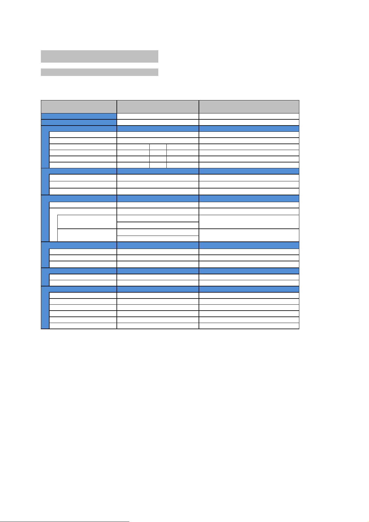
Specifications
Item
Specifications
Notes
Column type air micrometer
CAG300011
20501001640800.2
0.5
1.0
0.4
1.0
2.0
Electric type
The air type model will have no
ZERO/MAG knobs in the future.
Minimum・Maximum
Real time
101dot BAR LED
2" TFT LCD
BAR LED Color
TFT LCD Color
2" TFT LCD
Chinese, Japanese, English
10
1 port
4ports(measure,RESET,min,max)
5 - 40
0.4 - 0.6
50
DC 7 - 12
2
2.5
3
Page 4
- -
Option
: Peak measurement function
: Rank display function
Orifice diameter & Board
Depending on a connected probe spec,
orifice dia and board configuration
will change.
: μm (Standard)
: μm (Standard)
Measurement range
: μm
: μm
: μm
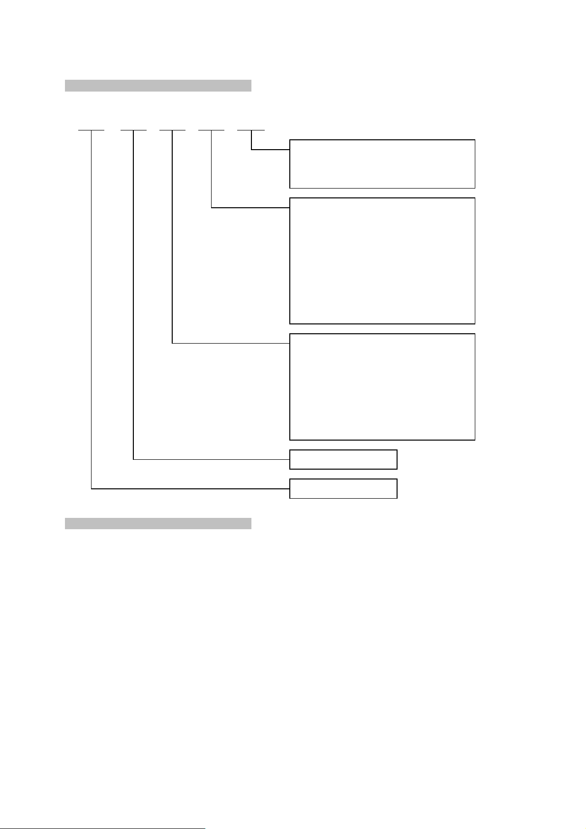
Model number
Standard model code
● AC adaptor
XXPR
Model
CAG30XXXX100
111
50/100
10
1032050
CAG0520
02
Standard Accessories
30
4
Page 5
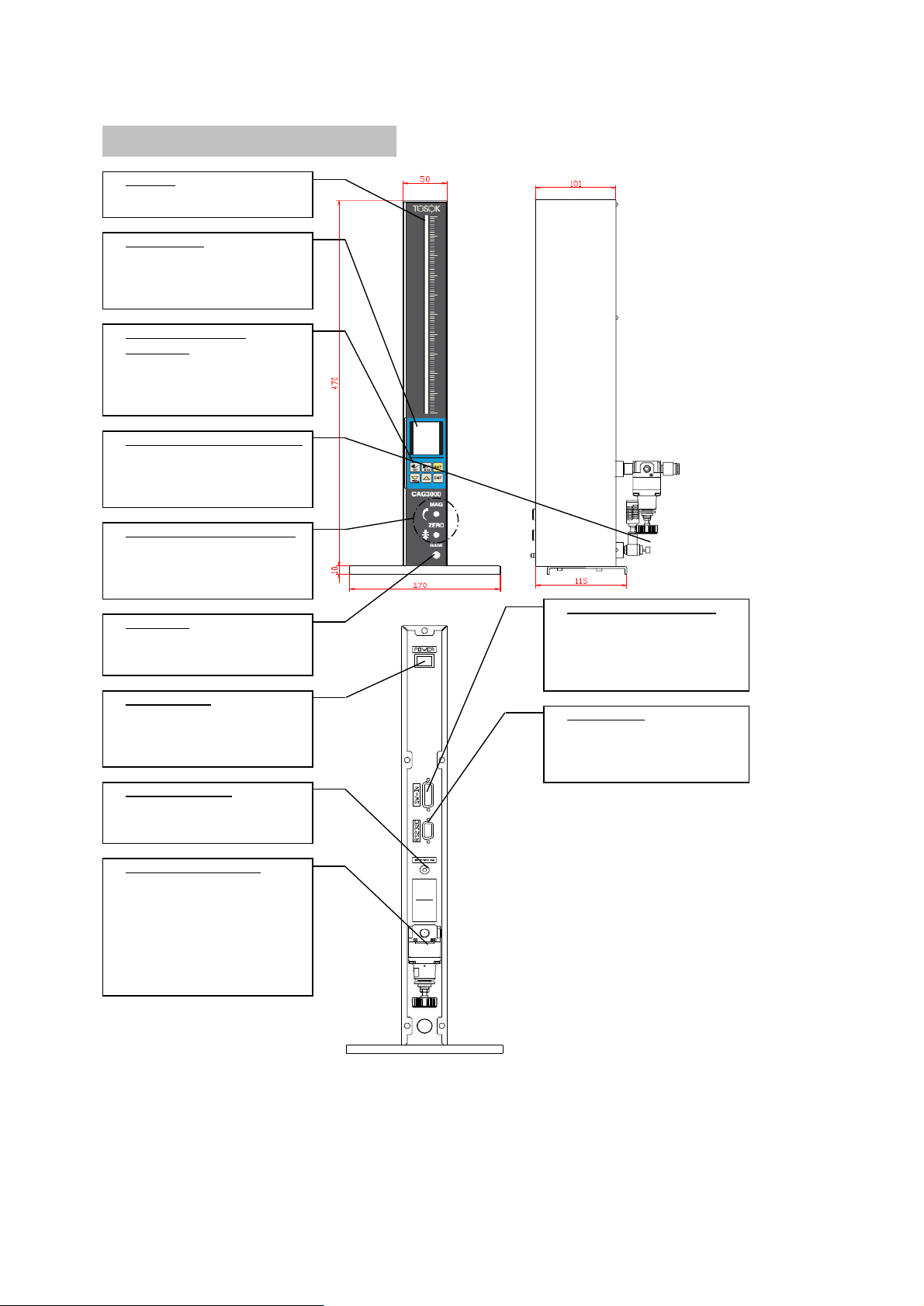
① BAR LED
Displays the meas. value
② LCD display
Displays the meas. value,
judgement result and
set values.
③ Panel switch for
mastering
Used to change mode and
set values for each type.
④ Pressure adjustment valve
Used when a mastering
error occurs during
measuring jig replacement.
⑤ ZERO/MAG Adjustment Knob
Used when a mastering
error occurs during
measuring jig replacement.
⑩ External switch input
⑥ GAGE port Used to connect
Connects the measuring jig push button or
like the measuring head foot switch.
and measuring block.
⑦ Power switch
Used to power ON/OFF ⑪
RS232C port
the device. Used to connect the
RS232C cable.
⑧ Power connector
Connects the AC adaptor.
⑨ Precision regulator
Supply pressure
0.4 - 0.6[MPa]
Please use clean air.
Used to adjust pressure.
Please do not operate
the handle.
3.Names/Functions of each part
5
Page 6
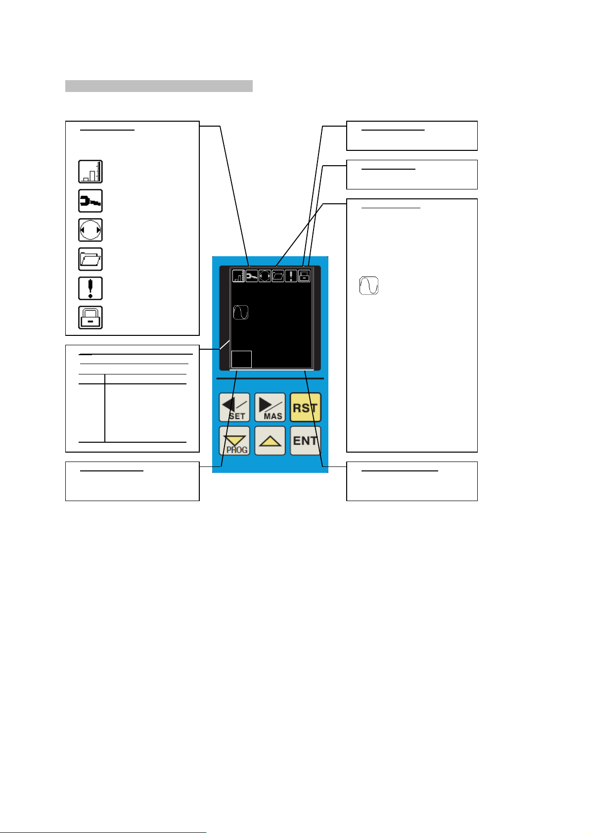
⑫ Mode display ⑮
Measured value
Displays the current mode
and condition.
Measurement mode ⑯ Unit display
Set mode
⑰ Value display
Displays the measured
Calibration mode value format.
When mastering is NG
※ Normally 「Raw data」
Program change mode is displayed only.
Error condition
Raw data
Measured value 最大値
hold condition
最小値
⑬ Displays judgement result
and mastering condition.
最大値-最小値
Disp
Detail
OK Result is “OK”
NG Result is “NG”
CAL Mastering request
condition.
Please perform
mastering.
⑭ Program number ⑱ Measurement range
Displays the current Displays the measurement
program number. range.
②.LCD display detail
最大値-最小値
2
最大値+最小値
2
20.0000
mm
1
50
μm
OK
6
Page 7

● Install the device on a stable Plug the AC adaptor to the power
and level surface with no source.
vibrations.
Set the device on the desired place. Turn "ON" the 「⑦.Power switch」.
! Warning ● Connect the air hose only when
power is turned OFF.
The opening demo will be shown.
Turn OFF the 「⑦.Power switch」.
Connect the air hose of the
measuring block to the
「⑥.GAGE port」. Software version shall be displayed.
Connect the air hose from the filter 起動プログラム番号
to the 「⑨.Precision regulator」. 測定レンジ
Please connect the 「AC Adaptor」 Turn "OFF" the 「⑦.Power switch」.
following the procedure below.
Turn "OFF" the 「⑥.Power switch」.
Unplug the AC adaptor from the
power source.
Connect the AC adaptor to the
「⑨.Power connector」. Unplug the AC adaptor from the
power source.
4.Installation
5.Power “ON”“OFF”
Installing the device
Supply the power
Important
1
2
Connect the air hose.
312
3
Connect the AC adaptor
Turn the power OFF
11232
6
9
7
7
CAG3000
Ver1.00
20.0000
mm
1
50
μm
OK
7
Page 8

Perform calibration by master.
● Mastering must be done on any of the
following conditions.
●
Air micrometer is a comparative
・ Every 2 to 4 hours
measuring device. ・ When power or air supply is turned "ON".
The precision cannot be guaranteed if ・ When indicated value looks abnormal.
there are dirt, scratch, dent or rust
on the master or measurement jig.
Press
for more than 2 secs.
● Precision is not guaranteed if measurement Mode display will change to .
jigs made by other companies is connected
to the device.
● Air micrometer is weak on water and oil.
In case water or oil gets in the device,
the following conditions may happen :
・ Precision becomes bad.
・ The displayed value becomes unstable.
・ Different values are displayed
for the same measured object.
By periodically replacing the filter
element, the above conditions can be
prevented from happening.
Set 「Min master」 the measurement jig.
We recommend the overhaul of the device Once the indicator stabilizes,
if water or oil gets inside the main press .
unit.
Set 「Max master」 on measurement jig.
Check the filter condition. Once the indicator stabilizes,
● Is water or oil clogged up? press .
Check the measure jigs and master.
● Any dirt, scratch, dent or rust? Perform 「Max mastering」.
With compressed air, turn the power
"ON". Check the display of 「TFT LCD」.
After the opening demo, 「MAS OK」 Mastering is successful.
「CAL」 shall be displayed. Proceed to measurement.
Please perform mastering.
「ERR ZERO」
「ERR MAG 」 There is error if any of
Chinese English 「ERR REV 」 these three appears.
Please deal with the cause
of the mastering error.
If error occurs, please confirm and correct
the condition.
・ Is the supply pressure correct?
・ Was the min master and max master
taken by mistake?
・ Is there any dirt, scratch, dent or rust
on the measure jig or master?
・ If none of the above, proceed to
8. Adjustments and perform the task.
6.Operating Procedure
Mastering
Preparations before measurement
Important
Important
567
12384
Mastering error processing
20.0000
mm
1
50
μm
OK
1 .
校准标准件
0
100
1/3
下限标准件值
20.000
20.000
mm
μm
1 .
mm
1/3
20.000
20.000
Calibration
Min Master
0
100
μm
8
Page 9

Measure the work object. Hold the measured value and output
! Caution it to RS232C.
● During measurement mode, ! Caution
By pressing for more than 2 secs. ● If the mastering is NG, you cannot
hold and output the measured value.
the mode will change to Master mode.
With the mode display at ,
In order to maintain the measurement
press
.
accuracy, perform mastering about every
2 hours. The measured value shall be held
and hold condition is displayed.
Set the work object on the measurement
jig. The measured value and judegement
The measured value and judgement result shall output to RS232C.
result shall be displayed.
If the color of the「BAR LED」is …
“green”, value is OK and in range.
“red”, value is out of range.
O K N G
If is pressed,
the display shall disappear
and reset the measured value hold
condition.
Measurement
Hold/Output meas. value
112
2
20.0000
mm
1
50
μm
OK
1 .
校准标准件
0
100
1/3
下限标准件值
20.000
20.000
mm
μm
1 .
mm
1/3
20.000
20.000
Calibration
Min Master
0
100
μm
9
Page 10

Input the new set value of the measurement jig.
It is possible to store up up to 10 types of
measurement conditions.
Input new set values to a program. ! Caution
● Changing the measurement range
The user cannot change the measurement
! Caution range.
● In case you will change the settings In case you need to change the setting,
of the current program, the device has to be pulled out for
do the following procedure modification.
「Input set value」. ● Changing the measure jig JET diameter
In case you need to change the measurement
Turn "ON" the power. jig JET diameter, the device maybe
After the opening demo, pulled out for modification.
「 CAL 」 shall be displayed.
Japanese
● The set mode has 2 component displays.
Chinese English 「Set items」 selection display and
「 Set values 」input display.
●
Selection of set items procedure
Press for more than 2 secs.
The mode display will change to .
There are multiple pages.
Press
. Under set item display
Upper box displays current program no.
Lower box displays the new program no.
Press to 「Select」
input.
then press to 「Set」
● Set values input procedure
Upper box displays
current value.
Lower box displays
changed value.
Press to move
input digit.
The program is selected by .
Press
to change
Press
and the mode display
the value.
will change to .
Press to set value.
7.Setting Procedure
Input set value
Program change
1
Important
2
4
设定 项 目名称
1 .
2 .
3 .
4 .
5 .
6 .
7 .
8 .
上限标准件值
下限标准件值
上限超差值
下限超差值
公差中间值
公差中间单位
选择量程
极性
1/2
20.0000
mm
1
50
μm
OK
切换程序
程序编号
0
0
Label
1 .
2 .
3 .
4 .
5 .
6 .
7 .
8 .
Max Master
Min Master
+NG/ OK
OK/-NG
Shift Value
Shift Unit
Range
Polarity
1/2
1 .
校准标准件
0
100
1/3
下限标准件值
20.000
20.000
mm
μm
1 .
mm
1/3
20.000
20.000
Calibration
Min Master
0
100
μm
Program Change
Program No.
0
0
LABEL
1 .
1.
1.
2.
1/2
Polarity
+
+
-
10
Page 11

Press for more 2 seconds Setting the measured value display unit.
Select
「 Shift unit 」 then SET.
Display will change to as below
If in μm, select
「 1.μm 」
If in mm, select
「 2.mm 」
Chinese English Chinese English
Setting the polarity. Setting shift value of measurements.
Select
「
Polarity
」 then SET.
Select
「
Shift Value
」 then SET.
For Inner diameter, 「 1.+ 」 Input 「Work tolerance
For outer diameter, 「 2.- 」 target value(median)」.
Chinese English Chinese English
Setting the measurement range. Setting work upper tolerance limit value.
Select
「 Range 」 then SET.
Select
「 +NG/OK 」 then SET.
Select the measurement range as Input upper tolerance limit value.
stated on the nameplate of the
measurement jig.
Chinese English Chinese English
14253
6
设定 项 目名称
1 .
2 .
3 .
4 .
5 .
6 .
7 .
8 .
上限标准件值
下限标准件值
上限超差值
下限超差值
公差中间值
公差中间单位
选择量程
极性
1/2
20.0000
mm
1
50
μm
OK
切换程序
程序编号
0
0
Label
1 .
2 .
3 .
4 .
5 .
6 .
7 .
8 .
Max Master
Min Master
+NG/ OK
OK/-NG
Shift Value
Shift Unit
Range
Polarity
1/2
1 .
校准标准件
0
100
1/3
下限标准件值
20.000
20.000
mm
μm
1 .
mm
1/3
20.000
20.000
Calibration
Min Master
0
100
μm
设定 项 目名称
1 .
2 .
3 .
4 .
5 .
6 .
7 .
8 .
上限标准件值
下限标准件值
上限超差值
下限超差值
公差中间值
公差中间单位
选择量程
极性
1/2
Label
1 .
2 .
3 .
4 .
5 .
6 .
7 .
8 .
Max Master
Min Master
+NG/ OK
OK/-NG
Shift Value
Shift Unit
Range
Polarity
1/2
设定 项 目名称
1 .
2 .
3 .
4 .
5 .
6 .
7 .
8 .
上限标准件值
下限标准件值
上限超差值
下限超差值
公差中间值
公差中间单位
选择量程
极性
1/2
Label
1 .
2 .
3 .
4 .
5 .
6 .
7 .
8 .
Max Master
Min Master
+NG/ OK
OK/-NG
Shift Value
Shift Unit
Range
Polarity
1/2
设定 项 目名称
1 .
2 .
3 .
4 .
5 .
6 .
7 .
8 .
上限标准件值
下限标准件值
上限超差值
下限超差值
公差中间值
公差中间单位
选择量程
极性
1/2
Label
1 .
2 .
3 .
4 .
5 .
6 .
7 .
8 .
Max Master
Min Master
+NG/ OK
OK/-NG
Shift Value
Shift Unit
Range
Polarity
1/2
设定 项 目名称
1 .
2 .
3 .
4 .
5 .
6 .
7 .
8 .
上限标准件值
下限标准件值
上限超差值
下限超差值
公差中间值
公差中间单位
选择量程
极性
1/2
Label
1 .
2 .
3 .
4 .
5 .
6 .
7 .
8 .
Max Master
Min Master
+NG/ OK
OK/-NG
Shift Value
Shift Unit
Range
Polarity
1/2
设定 项 目名称
1 .
2 .
3 .
4 .
5 .
6 .
7 .
8 .
9 .
下限标准件值
下限超差值
上限标准件值
上限超差值
公差中间值
公差中间单位
选择量程
极性
1/2
Label
1 .
2 .
3 .
4 .
5 .
6 .
7 .
8 .
Min Master
OK/-NG
Max Master
+NG/ OK
Shift Value
Shift Unit
Range
Polarity
1/2
设定 项 目名称
1 .
2 .
3 .
4 .
5 .
6 .
7 .
8 .
上限标准件值
下限标准件值
上限超差值
下限超差值
公差中间值
公差中间单位
选择量程
极性
1/2
Label
1 .
2 .
3 .
4 .
5 .
6 .
7 .
8 .
Max Master
Min Master
+NG/ OK
OK/-NG
Shift Value
Shift Unit
Range
Polarity
1/2
Program Change
Program No.
0
0
LABEL
1 .
1.
1.
2.
1/2
Polarity
+
+
-
11
Page 12

Setting work lower tolerance limit value.
Setting the language.
Select
「 OK/-NG 」 then SET.
Select
「
Language
」 then SET.
Input lower tolerance limit value. Select preferred display language.
Chinese English Chinese English
Setting the max master value.
Setting all the values changed.
Select
「 Max Master 」 then SET.
Select
「 End 」 then SET.
Input the engraved characters Select 「Cancel」 if you don’t
value on the max master. want to save the set values.
Select 「Write」 if you want
to save the set values.
Chinese English Chinese English
Setting the min master value.
This concludes the program setting.
Select
「 Min Master 」 then SET. Proceed to 「8.Adjustment」
Input the engraved characters
value on the min master.
Chinese English
7108911
设定 项 目名称
1 .
2 .
3 .
4 .
5 .
6 .
7 .
8 .
上限标准件值
下限标准件值
上限超差值
下限超差值
公差中间值
公差中间单位
选择量程
极性
1/2
20.0000
mm
1
50
μm
OK
切换程序
程序编号
0
0
Label
1 .
2 .
3 .
4 .
5 .
6 .
7 .
8 .
Max Master
Min Master
+NG/ OK
OK/-NG
Shift Value
Shift Unit
Range
Polarity
1/2
1 .
校准标准件
0
100
1/3
下限标准件值
20.000
20.000
mm
μm
1 .
mm
1/3
20.000
20.000
Calibration
Min Master
0
100
μm
设定 项 目名称
1 .
2 .
3 .
4 .
5 .
6 .
7 .
8 .
上限标准件值
下限标准件值
上限超差值
下限超差值
公差中间值
公差中间单位
选择量程
极性
1/2
Label
1 .
2 .
3 .
4 .
5 .
6 .
7 .
8 .
Max Master
Min Master
+NG/ OK
OK/-NG
Shift Value
Shift Unit
Range
Polarity
1/2
设定 项 目名称
1 .
2 .
3 .
4 .
5 .
6 .
7 .
8 .
上限标准件值
下限标准件值
上限超差值
下限超差值
公差中间值
公差中间单位
选择量程
极性
1/2
Label
1 .
2 .
3 .
4 .
5 .
6 .
7 .
8 .
Max Master
Min Master
+NG/ OK
OK/-NG
Shift Value
Shift Unit
Range
Polarity
1/2
设定 项 目名称
1 .
2 .
3 .
4 .
5 .
6 .
7 .
8 .
上限标准件值
下限标准件值
上限超差值
下限超差值
公差中间值
公差中间单位
选择量程
极性
1/2
Label
1 .
2 .
3 .
4 .
5 .
6 .
7 .
8 .
Max Master
Min Master
+NG/ OK
OK/-NG
Shift Value
Shift Unit
Range
Polarity
1/2
设定 项 目名称
1 .
2 .
3 .
4 .
5 .
6 .
7 .
8 .
上限标准件值
下限标准件值
上限超差值
下限超差值
公差中间值
公差中间单位
选择量程
极性
1/2
Label
1 .
2 .
3 .
4 .
5 .
6 .
7 .
8 .
Max Master
Min Master
+NG/ OK
OK/-NG
Shift Value
Shift Unit
Range
Polarity
1/2
设定 项 目名称
1 .
2 .
3 .
4 .
5 .
6 .
7 .
8 .
9 .
下限标准件值
下限超差值
上限标准件值
上限超差值
公差中间值
公差中间单位
选择量程
极性
1/2
Label
1 .
2 .
3 .
4 .
5 .
6 .
7 .
8 .
Min Master
OK/-NG
Max Master
+NG/ OK
Shift Value
Shift Unit
Range
Polarity
1/2
设定 项 目名称
1 .
2 .
3 .
4 .
5 .
6 .
7 .
8 .
上限标准件值
下限标准件值
上限超差值
下限超差值
公差中间值
公差中间单位
选择量程
极性
1/2
Label
1 .
2 .
3 .
4 .
5 .
6 .
7 .
8 .
Max Master
Min Master
+NG/ OK
OK/-NG
Shift Value
Shift Unit
Range
Polarity
1/2
设定 项 目名称
1 .
2 .
3 .
4 .
5 .
6 .
7 .
8 .
上限标准件值
下限标准件值
上限超差值
下限超差值
公差中间值
公差中间单位
选择量程
极性
1/2
Label
1 .
2 .
3 .
4 .
5 .
6 .
7 .
8 .
Max Master
Min Master
+NG/ OK
OK/-NG
Shift Value
Shift Unit
Range
Polarity
1/2
Label
1 .
2 .
3 .
4 .
5 .
6 .
7 .
8 .
Min Master
Max Master
OK/-NG
+NG/ OK
Shift Value
Shift Unit
Range
Polarity
1/2
设定 项 目名称
1 .
2 .
3 .
4 .
5 .
6 .
7 .
8 .
上限标准件值
下限标准件值
下限超差值
上限超差值
公差中间单位
公差中间值
选择量程
极性
1/2
设定 项 目名称
1 .
2 .
3 .
4 .
5 .
6 .
7 .
8 .
下限标准件值
上限标准件值
上限超差值
下限超差值
公差中间值
公差中间单位
极性
选择量程
1/2
Label
1 .
2 .
3 .
4 .
5 .
6 .
7 .
8 .
Min Master
Max Master
OK/-NG
+NG/ OK
Shift Value
Shift Unit
Range
Polarity
1/2
设定 项 目名称
9 .
10 .
结束
Language(语言)
2/2
Label
9 .
10 .
END
Language
2/2
Label
9 .
10 .
END
Language
2/2
设定 项 目名称
9 .
10 .
结束
Language(语言)
2/2
Program Change
Program No.
0
0
LABEL
1 .
1.
1.
2.
1/2
Polarity
+
+
-
12
Page 13

Turn the ZERO adj knob full to the
right then turn it to the left
2.5 times.
Adjust CAG measurement standard pressure.
ZERO adj. knob
Press for more than 2 secs.
The mode display will change to
Chinese English
When the min master and max master is
placed, adjust the standard pressure
valve so the position of the BAR LED
display is divided in the center.
Standard pressure
adjustment valve
Press .「ADJ」 will be displayed.
Chinese English
8.Adjustment
3
Adjust the standard pressure
142
设定 项 目名称
1 .
2 .
3 .
4 .
5 .
6 .
7 .
8 .
上限标准件值
下限标准件值
上限超差值
下限超差值
公差中间值
公差中间单位
选择量程
极性
1/2
20.0000
mm
1
50
μm
OK
切换程序
程序编号
0
0
Label
1 .
2 .
3 .
4 .
5 .
6 .
7 .
8 .
Max Master
Min Master
+NG/ OK
OK/-NG
Shift Value
Shift Unit
Range
Polarity
1/2
1 .
μm
1/3
下限标准件值
20.000
20.000
mm
校准标准件
0
100
1 .
0
100
μm
mm
1/3
20.000
20.000
Calibration
Min Master
1 .
-30
μm
0
100
μm
调整
2/3
調整
1 .
校准标准件
0
100
1/3
下限标准件值
20.000
20.000
mm
μm
1 .
mm
1/3
20.000
20.000
Calibration
Min Master
0
100
μm
设定 项 目名称
1 .
2 .
3 .
4 .
5 .
6 .
7 .
8 .
上限标准件值
下限标准件值
上限超差值
下限超差值
公差中间值
公差中间单位
选择量程
极性
1/2
Label
1 .
2 .
3 .
4 .
5 .
6 .
7 .
8 .
Max Master
Min Master
+NG/ OK
OK/-NG
Shift Value
Shift Unit
Range
Polarity
1/2
设定 项 目名称
1 .
2 .
3 .
4 .
5 .
6 .
7 .
8 .
上限标准件值
下限标准件值
上限超差值
下限超差值
公差中间值
公差中间单位
选择量程
极性
1/2
Label
1 .
2 .
3 .
4 .
5 .
6 .
7 .
8 .
Max Master
Min Master
+NG/ OK
OK/-NG
Shift Value
Shift Unit
Range
Polarity
1/2
设定 项 目名称
1 .
2 .
3 .
4 .
5 .
6 .
7 .
8 .
上限标准件值
下限标准件值
上限超差值
下限超差值
公差中间值
公差中间单位
选择量程
极性
1/2
Label
1 .
2 .
3 .
4 .
5 .
6 .
7 .
8 .
Max Master
Min Master
+NG/ OK
OK/-NG
Shift Value
Shift Unit
Range
Polarity
1/2
设定 项 目名称
1 .
2 .
3 .
4 .
5 .
6 .
7 .
8 .
上限标准件值
下限标准件值
上限超差值
下限超差值
公差中间值
公差中间单位
选择量程
极性
1/2
Label
1 .
2 .
3 .
4 .
5 .
6 .
7 .
8 .
Max Master
Min Master
+NG/ OK
OK/-NG
Shift Value
Shift Unit
Range
Polarity
1/2
设定 项 目名称
1 .
2 .
3 .
4 .
5 .
6 .
7 .
8 .
9 .
下限标准件值
下限超差值
上限标准件值
上限超差值
公差中间值
公差中间单位
选择量程
极性
1/2
Label
1 .
2 .
3 .
4 .
5 .
6 .
7 .
8 .
Min Master
OK/-NG
Max Master
+NG/ OK
Shift Value
Shift Unit
Range
Polarity
1/2
设定 项 目名称
1 .
2 .
3 .
4 .
5 .
6 .
7 .
8 .
上限标准件值
下限标准件值
上限超差值
下限超差值
公差中间值
公差中间单位
选择量程
极性
1/2
Label
1 .
2 .
3 .
4 .
5 .
6 .
7 .
8 .
Max Master
Min Master
+NG/ OK
OK/-NG
Shift Value
Shift Unit
Range
Polarity
1/2
设定 项 目名称
1 .
2 .
3 .
4 .
5 .
6 .
7 .
8 .
上限标准件值
下限标准件值
上限超差值
下限超差值
公差中间值
公差中间单位
选择量程
极性
1/2
Label
1 .
2 .
3 .
4 .
5 .
6 .
7 .
8 .
Max Master
Min Master
+NG/ OK
OK/-NG
Shift Value
Shift Unit
Range
Polarity
1/2
Label
1 .
2 .
3 .
4 .
5 .
6 .
7 .
8 .
Min Master
Max Master
OK/-NG
+NG/ OK
Shift Value
Shift Unit
Range
Polarity
1/2
设定 项 目名称
1 .
2 .
3 .
4 .
5 .
6 .
7 .
8 .
上限标准件值
下限标准件值
下限超差值
上限超差值
公差中间单位
公差中间值
选择量程
极性
1/2
设定 项 目名称
1 .
2 .
3 .
4 .
5 .
6 .
7 .
8 .
下限标准件值
上限标准件值
上限超差值
下限超差值
公差中间值
公差中间单位
极性
选择量程
1/2
Label
1 .
2 .
3 .
4 .
5 .
6 .
7 .
8 .
Min Master
Max Master
OK/-NG
+NG/ OK
Shift Value
Shift Unit
Range
Polarity
1/2
设定 项 目名称
9 .
10 .
结束
Language(语言)
2/2
Label
9 .
10 .
END
Language
2/2
Label
9 .
10 .
END
Language
2/2
设定 项 目名称
9 .
10 .
结束
Language(语言)
2/2
1 . Adjustment
100
μm
2/3
Adjustment
-30
μm
1
Program Change
Program No.
0
0
LABEL
1 .
1.
1.
2.
1/2
Polarity
+
+
-
13
Page 14

Adjusts the ZERO and MAG Set min master on the measurement jig.
position of the measurement Adjust 「ZERO 」 so the indicator
jig and CAG. is close to the min master value.
The magnification
is adjusted with Set max master on the measurement jig.
「MAG 」 and zero is Adjust 「MAG 」 so the indicator
adjusted with 「ZERO」 is close to the max master value.
knob.
Set min master on the measurement jig.
When the indicator is close to the
min master value, the adjustment
is completed. Proceed to 11 .
● Adjustment procedure
For inner diameter measurement,
proceed to 5 .
For outer diameter measurement,
proceed to 8 .
Set max master on the measurement jig.
Adjust 「ZERO 」 so the indicator
is close to the max master value.
Set min master on the measurement jig.
Adjust 「MAG 」 so the indicator
is close to the min master value.
Set max master on the measurement jig.
When the indicator is close to the
max master value, the adjustment
is completed. Proceed to 11 .
Green bar dot display :
Upper part 「Max master」
Lower part 「Min master」
(set values)
ZERO・MAG Adjustment
Inner diameter measurement
567
Outer diameter measurement
8910
设定 项 目名称
1 .
2 .
3 .
4 .
5 .
6 .
7 .
8 .
上限标准件值
下限标准件值
上限超差值
下限超差值
公差中间值
公差中间单位
选择量程
极性
1/2
20.0000
mm
1
50
μm
OK
切换程序
程序编号
0
0
Label
1 .
2 .
3 .
4 .
5 .
6 .
7 .
8 .
Max Master
Min Master
+NG/ OK
OK/-NG
Shift Value
Shift Unit
Range
Polarity
1/2
1 .
μm
1/3
下限标准件值
20.000
20.000
mm
校准标准件
0
100
1 .
0
100
μm
mm
1/3
20.000
20.000
Calibration
Min Master
1 .
-30
μm
0
100
μm
调整
2/3
調整
1 .
校准标准件
0
100
1/3
下限标准件值
20.000
20.000
mm
μm
1 .
mm
1/3
20.000
20.000
Calibration
Min Master
0
100
μm
设定 项 目名称
1 .
2 .
3 .
4 .
5 .
6 .
7 .
8 .
上限标准件值
下限标准件值
上限超差值
下限超差值
公差中间值
公差中间单位
选择量程
极性
1/2
Label
1 .
2 .
3 .
4 .
5 .
6 .
7 .
8 .
Max Master
Min Master
+NG/ OK
OK/-NG
Shift Value
Shift Unit
Range
Polarity
1/2
设定 项 目名称
1 .
2 .
3 .
4 .
5 .
6 .
7 .
8 .
上限标准件值
下限标准件值
上限超差值
下限超差值
公差中间值
公差中间单位
选择量程
极性
1/2
Label
1 .
2 .
3 .
4 .
5 .
6 .
7 .
8 .
Max Master
Min Master
+NG/ OK
OK/-NG
Shift Value
Shift Unit
Range
Polarity
1/2
设定 项 目名称
1 .
2 .
3 .
4 .
5 .
6 .
7 .
8 .
上限标准件值
下限标准件值
上限超差值
下限超差值
公差中间值
公差中间单位
选择量程
极性
1/2
Label
1 .
2 .
3 .
4 .
5 .
6 .
7 .
8 .
Max Master
Min Master
+NG/ OK
OK/-NG
Shift Value
Shift Unit
Range
Polarity
1/2
设定 项 目名称
1 .
2 .
3 .
4 .
5 .
6 .
7 .
8 .
上限标准件值
下限标准件值
上限超差值
下限超差值
公差中间值
公差中间单位
选择量程
极性
1/2
Label
1 .
2 .
3 .
4 .
5 .
6 .
7 .
8 .
Max Master
Min Master
+NG/ OK
OK/-NG
Shift Value
Shift Unit
Range
Polarity
1/2
设定 项 目名称
1 .
2 .
3 .
4 .
5 .
6 .
7 .
8 .
9 .
下限标准件值
下限超差值
上限标准件值
上限超差值
公差中间值
公差中间单位
选择量程
极性
1/2
Label
1 .
2 .
3 .
4 .
5 .
6 .
7 .
8 .
Min Master
OK/-NG
Max Master
+NG/ OK
Shift Value
Shift Unit
Range
Polarity
1/2
设定 项 目名称
1 .
2 .
3 .
4 .
5 .
6 .
7 .
8 .
上限标准件值
下限标准件值
上限超差值
下限超差值
公差中间值
公差中间单位
选择量程
极性
1/2
Label
1 .
2 .
3 .
4 .
5 .
6 .
7 .
8 .
Max Master
Min Master
+NG/ OK
OK/-NG
Shift Value
Shift Unit
Range
Polarity
1/2
设定 项 目名称
1 .
2 .
3 .
4 .
5 .
6 .
7 .
8 .
上限标准件值
下限标准件值
上限超差值
下限超差值
公差中间值
公差中间单位
选择量程
极性
1/2
Label
1 .
2 .
3 .
4 .
5 .
6 .
7 .
8 .
Max Master
Min Master
+NG/ OK
OK/-NG
Shift Value
Shift Unit
Range
Polarity
1/2
Label
1 .
2 .
3 .
4 .
5 .
6 .
7 .
8 .
Min Master
Max Master
OK/-NG
+NG/ OK
Shift Value
Shift Unit
Range
Polarity
1/2
设定 项 目名称
1 .
2 .
3 .
4 .
5 .
6 .
7 .
8 .
上限标准件值
下限标准件值
下限超差值
上限超差值
公差中间单位
公差中间值
选择量程
极性
1/2
设定 项 目名称
1 .
2 .
3 .
4 .
5 .
6 .
7 .
8 .
下限标准件值
上限标准件值
上限超差值
下限超差值
公差中间值
公差中间单位
极性
选择量程
1/2
Label
1 .
2 .
3 .
4 .
5 .
6 .
7 .
8 .
Min Master
Max Master
OK/-NG
+NG/ OK
Shift Value
Shift Unit
Range
Polarity
1/2
设定 项 目名称
9 .
10 .
结束
Language(语言)
2/2
Label
9 .
10 .
END
Language
2/2
Label
9 .
10 .
END
Language
2/2
设定 项 目名称
9 .
10 .
结束
Language(语言)
2/2
1 . Adjustment
100
μm
2/3
Adjustment
-30
μm
1
Program Change
Program No.
0
0
LABEL
1 .
1.
1.
2.
1/2
Polarity
+
+
-
14
Page 15

Set 「Max Master」 on measurement jig.
After the indicators stabilizes,
press .Calibration of the min master 「Max Master」 is performed.
and max master.
Chinese English
! Caution
● Master
Use only those with no rust
or dirt on it.
● Frequency of calibration
In order to maintain the accuracy,
it is highly suggested to do the
calibration every 2 hours.
After the adjustment is completed,
press .「1. Min Master」 is displayed.
Check the display of 「TFT LCD」.
Chinese English 「MAS OK」 Mastering is successful.
Proceed to measurement.
Chinese English
Set 「Min Master」 on measurement jig.
After the indicators stabilizes,
press .After 「Min Master」 is performed,
「 2.Max Master 」 is displayed. 「ERR ZERO」
「ERR MAG 」 There is error if any of
「ERR REV 」 these three appears.
Chinese English
After pressing , proceed to
2
13
Calibration
111412
设定 项 目名称
1 .
2 .
3 .
4 .
5 .
6 .
7 .
8 .
上限标准件值
下限标准件值
上限超差值
下限超差值
公差中间值
公差中间单位
选择量程
极性
1/2
20.0000
mm
1
50
μm
OK
切换程序
程序编号
0
0
Label
1 .
2 .
3 .
4 .
5 .
6 .
7 .
8 .
Max Master
Min Master
+NG/ OK
OK/-NG
Shift Value
Shift Unit
Range
Polarity
1/2
1 .
μm
1/3
下限标准件值
20.000
20.000
mm
校准标准件
0
100
1 .
0
100
μm
mm
1/3
20.000
20.000
Calibration
Min Master
1 .
-30
μm
0
100
μm
调整
2/3
調整
1 .
μm
1/3
下限标准件值
20.000
20.000
mm
校准标准件
0
100
1 .
0
100
μm
mm
1/3
20.000
20.000
Calibration
Min Master
2 .
0
100
μm
mm
20.000
Max Master
20.060
Calibration
1/3
2 .
μm
校准标准件
1/3
0
100
mm
20.000
上限标准件值
20.060
2 .
μm
校准标准件
1/3
0
100
mm
20.060
上限标准件值
20.060
2 .
0
100
μm
mm
20.060
Max Master
20.060
Calibration
1/3
3 .
μm
0
100
校准結果
校准完成
校准标准件
1/3
3 .
0
100
μm
Master SET OK
Calibration
1/3
Result Master
1 .
校准标准件
0
100
1/3
下限标准件值
20.000
20.000
mm
μm
1 .
mm
1/3
20.000
20.000
Calibration
Min Master
0
100
μm
设定 项 目名称
1 .
2 .
3 .
4 .
5 .
6 .
7 .
8 .
上限标准件值
下限标准件值
上限超差值
下限超差值
公差中间值
公差中间单位
选择量程
极性
1/2
Label
1 .
2 .
3 .
4 .
5 .
6 .
7 .
8 .
Max Master
Min Master
+NG/ OK
OK/-NG
Shift Value
Shift Unit
Range
Polarity
1/2
设定 项 目名称
1 .
2 .
3 .
4 .
5 .
6 .
7 .
8 .
上限标准件值
下限标准件值
上限超差值
下限超差值
公差中间值
公差中间单位
选择量程
极性
1/2
Label
1 .
2 .
3 .
4 .
5 .
6 .
7 .
8 .
Max Master
Min Master
+NG/ OK
OK/-NG
Shift Value
Shift Unit
Range
Polarity
1/2
设定 项 目名称
1 .
2 .
3 .
4 .
5 .
6 .
7 .
8 .
上限标准件值
下限标准件值
上限超差值
下限超差值
公差中间值
公差中间单位
选择量程
极性
1/2
Label
1 .
2 .
3 .
4 .
5 .
6 .
7 .
8 .
Max Master
Min Master
+NG/ OK
OK/-NG
Shift Value
Shift Unit
Range
Polarity
1/2
设定 项 目名称
1 .
2 .
3 .
4 .
5 .
6 .
7 .
8 .
上限标准件值
下限标准件值
上限超差值
下限超差值
公差中间值
公差中间单位
选择量程
极性
1/2
Label
1 .
2 .
3 .
4 .
5 .
6 .
7 .
8 .
Max Master
Min Master
+NG/ OK
OK/-NG
Shift Value
Shift Unit
Range
Polarity
1/2
设定 项 目名称
1 .
2 .
3 .
4 .
5 .
6 .
7 .
8 .
9 .
下限标准件值
下限超差值
上限标准件值
上限超差值
公差中间值
公差中间单位
选择量程
极性
1/2
Label
1 .
2 .
3 .
4 .
5 .
6 .
7 .
8 .
Min Master
OK/-NG
Max Master
+NG/ OK
Shift Value
Shift Unit
Range
Polarity
1/2
设定 项 目名称
1 .
2 .
3 .
4 .
5 .
6 .
7 .
8 .
上限标准件值
下限标准件值
上限超差值
下限超差值
公差中间值
公差中间单位
选择量程
极性
1/2
Label
1 .
2 .
3 .
4 .
5 .
6 .
7 .
8 .
Max Master
Min Master
+NG/ OK
OK/-NG
Shift Value
Shift Unit
Range
Polarity
1/2
设定 项 目名称
1 .
2 .
3 .
4 .
5 .
6 .
7 .
8 .
上限标准件值
下限标准件值
上限超差值
下限超差值
公差中间值
公差中间单位
选择量程
极性
1/2
Label
1 .
2 .
3 .
4 .
5 .
6 .
7 .
8 .
Max Master
Min Master
+NG/ OK
OK/-NG
Shift Value
Shift Unit
Range
Polarity
1/2
Label
1 .
2 .
3 .
4 .
5 .
6 .
7 .
8 .
Min Master
Max Master
OK/-NG
+NG/ OK
Shift Value
Shift Unit
Range
Polarity
1/2
设定 项 目名称
1 .
2 .
3 .
4 .
5 .
6 .
7 .
8 .
上限标准件值
下限标准件值
下限超差值
上限超差值
公差中间单位
公差中间值
选择量程
极性
1/2
设定 项 目名称
1 .
2 .
3 .
4 .
5 .
6 .
7 .
8 .
下限标准件值
上限标准件值
上限超差值
下限超差值
公差中间值
公差中间单位
极性
选择量程
1/2
Label
1 .
2 .
3 .
4 .
5 .
6 .
7 .
8 .
Min Master
Max Master
OK/-NG
+NG/ OK
Shift Value
Shift Unit
Range
Polarity
1/2
设定 项 目名称
9 .
10 .
结束
Language(语言)
2/2
Label
9 .
10 .
END
Language
2/2
Label
9 .
10 .
END
Language
2/2
设定 项 目名称
9 .
10 .
结束
Language(语言)
2/2
1 . Adjustment
100
μm
2/3
Adjustment
-30
μm
1
Program Change
Program No.
0
0
LABEL
1 .
1.
1.
2.
1/2
Polarity
+
+
-
15
Page 16

It is possible to output the measured
data(value and judgement) to the RS232C.
! Caution While the mode display is ,
● If mastering is NG, it is not possible
to output the measured results. input “D” only.
● Use cable length of up to 15m only.
The data below is transmitted out.
Ex .
Measured value 「 20.0000」
● Connector cable
In case judgement is
「OK」
The 「RS232C connector」 at the rear
side is the connection port. SP CR LF
SP 2 0 . 0 0 0 0 SP SP O K CR LF
No No
1 6
2 7
3 8
4 9
5
● Serial port settings
Setting label
Bits / second
Data bits
Parity
Stop bits
● Output data composition
The output data is composed of the
14 characters found below.
・ Measured value 8 chars
・ Space(SP) 1 char
・ Judgement 3 chars
・ Control character(CR) 1 char
・ Control character(LF) 1 char
SP CR LF
2
Connect the RS232C cable
Signal label
Signal label
9.RS232C Output
RxD
RTS
TxD
CTS
GND
Set value
96008none1Measured value
Judgement
20.0000
OK
Measured results output
1
设定 项 目名称
1 .
2 .
3 .
4 .
5 .
6 .
7 .
8 .
上限标准件值
下限标准件值
上限超差值
下限超差值
公差中间值
公差中间单位
选择量程
极性
1/2
20.0000
mm
1
50
μm
OK
切换程序
程序编号
0
0
Label
1 .
2 .
3 .
4 .
5 .
6 .
7 .
8 .
Max Master
Min Master
+NG/ OK
OK/-NG
Shift Value
Shift Unit
Range
Polarity
1/2
1 .
μm
1/3
下限标准件值
20.000
20.000
mm
校准标准件
0
100
1 .
0
100
μm
mm
1/3
20.000
20.000
Calibration
Min Master
1 .
-30
μm
0
100
μm
调整
2/3
調整
1 .
μm
1/3
下限标准件值
20.000
20.000
mm
校准标准件
0
100
1 .
0
100
μm
mm
1/3
20.000
20.000
Calibration
Min Master
2 .
0
100
μm
mm
20.000
Max Master
20.060
Calibration
1/3
2 .
μm
校准标准件
1/3
0
100
mm
20.000
上限标准件值
20.060
2 .
μm
校准标准件
1/3
0
100
mm
20.060
上限标准件值
20.060
2 .
0
100
μm
mm
20.060
Max Master
20.060
Calibration
1/3
3 .
μm
0
100
校准結果
校准完成
校准标准件
1/3
3 .
0
100
μm
Master SET OK
Calibration
1/3
Result Master
1 .
校准标准件
0
100
1/3
下限标准件值
20.000
20.000
mm
μm
1 .
mm
1/3
20.000
20.000
Calibration
Min Master
0
100
μm
设定 项 目名称
1 .
2 .
3 .
4 .
5 .
6 .
7 .
8 .
上限标准件值
下限标准件值
上限超差值
下限超差值
公差中间值
公差中间单位
选择量程
极性
1/2
Label
1 .
2 .
3 .
4 .
5 .
6 .
7 .
8 .
Max Master
Min Master
+NG/ OK
OK/-NG
Shift Value
Shift Unit
Range
Polarity
1/2
设定 项 目名称
1 .
2 .
3 .
4 .
5 .
6 .
7 .
8 .
上限标准件值
下限标准件值
上限超差值
下限超差值
公差中间值
公差中间单位
选择量程
极性
1/2
Label
1 .
2 .
3 .
4 .
5 .
6 .
7 .
8 .
Max Master
Min Master
+NG/ OK
OK/-NG
Shift Value
Shift Unit
Range
Polarity
1/2
设定 项 目名称
1 .
2 .
3 .
4 .
5 .
6 .
7 .
8 .
上限标准件值
下限标准件值
上限超差值
下限超差值
公差中间值
公差中间单位
选择量程
极性
1/2
Label
1 .
2 .
3 .
4 .
5 .
6 .
7 .
8 .
Max Master
Min Master
+NG/ OK
OK/-NG
Shift Value
Shift Unit
Range
Polarity
1/2
设定 项 目名称
1 .
2 .
3 .
4 .
5 .
6 .
7 .
8 .
上限标准件值
下限标准件值
上限超差值
下限超差值
公差中间值
公差中间单位
选择量程
极性
1/2
Label
1 .
2 .
3 .
4 .
5 .
6 .
7 .
8 .
Max Master
Min Master
+NG/ OK
OK/-NG
Shift Value
Shift Unit
Range
Polarity
1/2
设定 项 目名称
1 .
2 .
3 .
4 .
5 .
6 .
7 .
8 .
9 .
下限标准件值
下限超差值
上限标准件值
上限超差值
公差中间值
公差中间单位
选择量程
极性
1/2
Label
1 .
2 .
3 .
4 .
5 .
6 .
7 .
8 .
Min Master
OK/-NG
Max Master
+NG/ OK
Shift Value
Shift Unit
Range
Polarity
1/2
设定 项 目名称
1 .
2 .
3 .
4 .
5 .
6 .
7 .
8 .
上限标准件值
下限标准件值
上限超差值
下限超差值
公差中间值
公差中间单位
选择量程
极性
1/2
Label
1 .
2 .
3 .
4 .
5 .
6 .
7 .
8 .
Max Master
Min Master
+NG/ OK
OK/-NG
Shift Value
Shift Unit
Range
Polarity
1/2
设定 项 目名称
1 .
2 .
3 .
4 .
5 .
6 .
7 .
8 .
上限标准件值
下限标准件值
上限超差值
下限超差值
公差中间值
公差中间单位
选择量程
极性
1/2
Label
1 .
2 .
3 .
4 .
5 .
6 .
7 .
8 .
Max Master
Min Master
+NG/ OK
OK/-NG
Shift Value
Shift Unit
Range
Polarity
1/2
Label
1 .
2 .
3 .
4 .
5 .
6 .
7 .
8 .
Min Master
Max Master
OK/-NG
+NG/ OK
Shift Value
Shift Unit
Range
Polarity
1/2
设定 项 目名称
1 .
2 .
3 .
4 .
5 .
6 .
7 .
8 .
上限标准件值
下限标准件值
下限超差值
上限超差值
公差中间单位
公差中间值
选择量程
极性
1/2
设定 项 目名称
1 .
2 .
3 .
4 .
5 .
6 .
7 .
8 .
下限标准件值
上限标准件值
上限超差值
下限超差值
公差中间值
公差中间单位
极性
选择量程
1/2
Label
1 .
2 .
3 .
4 .
5 .
6 .
7 .
8 .
Min Master
Max Master
OK/-NG
+NG/ OK
Shift Value
Shift Unit
Range
Polarity
1/2
设定 项 目名称
9 .
10 .
结束
Language(语言)
2/2
Label
9 .
10 .
END
Language
2/2
Label
9 .
10 .
END
Language
2/2
设定 项 目名称
9 .
10 .
结束
Language(语言)
2/2
1 . Adjustment
100
μm
2/3
Adjustment
-30
μm
1
Program Change
Program No.
0
0
LABEL
1 .
1.
1.
2.
1/2
Polarity
+
+
-
16
Page 17

Calibration of masters with the use of
external switch.
If the device is connected with external
push button or foot switch, the following
operations are possible.
・ Output and Hold of measured value.
・ Mastering
Set 「Min Master」 on measurement jig.
! Caution After the indicators stabilizes,
● Use cable length of up to 2m only. turn "ON" the External Switch Input
● It is possible to connect no voltage 「Min Master」.
contact point push button/foot switch.
「Min Master」is performed.
● Input connector
Connect to D-SUB15P(Male).
No No
1 9 Max Master
2 10 Min Master
3 11
4 12
5 13
GND 6 14 Set 「Max Master」 on measurement jig.
MEAS 7 15 After the indicators stabilizes,
RESET 8 turn "ON" the External Switch Input
「Max Master」.
「Max Master」is performed.
If this mark disappears,
mastering is successful.
Proceed to measurement.
The output to RS232C and hold of measured
value is done with the use of the
external switch. If this mark is blinking,
! Caution mastering is failed.
● If the mastering result is NG, Please deal with the cause
the output and hold of measured value
of the mastering error.
is not possible.
With the mode display at ,
turn "ON" the
External Switch Input「MEAS」.
The icon is displayed to
show the measure hold condition.
The measured value and judgement
result shall be output to the RS232C.
Turn "ON" the
External Switch Input「RESET」.
The icon will disappear to show
the measured value hold condition
is RESET.
10
.
External Switch Input
Mastering
External switch input
3
Signal label信号名
Signal label
4
5
Meas. Value Hold/Output
1
2
设定 项 目名称
1 .
2 .
3 .
4 .
5 .
6 .
7 .
8 .
上限标准件值
下限标准件值
上限超差值
下限超差值
公差中间值
公差中间单位
选择量程
极性
1/2
20.0000
mm
1
50
μm
OK
切换程序
程序编号
0
0
Label
1 .
2 .
3 .
4 .
5 .
6 .
7 .
8 .
Max Master
Min Master
+NG/ OK
OK/-NG
Shift Value
Shift Unit
Range
Polarity
1/2
1 .
μm
1/3
下限标准件值
20.000
20.000
mm
校准标准件
0
100
1 .
0
100
μm
mm
1/3
20.000
20.000
Calibration
Min Master
1 .
-30
μm
0
100
μm
调整
2/3
調整
1 .
μm
1/3
下限标准件值
20.000
20.000
mm
校准标准件
0
100
1 .
0
100
μm
mm
1/3
20.000
20.000
Calibration
Min Master
2 .
0
100
μm
mm
20.000
Max Master
20.060
Calibration
1/3
2 .
μm
校准标准件
1/3
0
100
mm
20.000
上限标准件值
20.060
2 .
μm
校准标准件
1/3
0
100
mm
20.060
上限标准件值
20.060
2 .
0
100
μm
mm
20.060
Max Master
20.060
Calibration
1/3
3 .
μm
0
100
校准結果
校准完成
校准标准件
1/3
3 .
0
100
μm
Master SET OK
Calibration
1/3
Result Master
1 .
校准标准件
0
100
1/3
下限标准件值
20.000
20.000
mm
μm
1 .
mm
1/3
20.000
20.000
Calibration
Min Master
0
100
μm
设定 项 目名称
1 .
2 .
3 .
4 .
5 .
6 .
7 .
8 .
上限标准件值
下限标准件值
上限超差值
下限超差值
公差中间值
公差中间单位
选择量程
极性
1/2
Label
1 .
2 .
3 .
4 .
5 .
6 .
7 .
8 .
Max Master
Min Master
+NG/ OK
OK/-NG
Shift Value
Shift Unit
Range
Polarity
1/2
设定 项 目名称
1 .
2 .
3 .
4 .
5 .
6 .
7 .
8 .
上限标准件值
下限标准件值
上限超差值
下限超差值
公差中间值
公差中间单位
选择量程
极性
1/2
Label
1 .
2 .
3 .
4 .
5 .
6 .
7 .
8 .
Max Master
Min Master
+NG/ OK
OK/-NG
Shift Value
Shift Unit
Range
Polarity
1/2
设定 项 目名称
1 .
2 .
3 .
4 .
5 .
6 .
7 .
8 .
上限标准件值
下限标准件值
上限超差值
下限超差值
公差中间值
公差中间单位
选择量程
极性
1/2
Label
1 .
2 .
3 .
4 .
5 .
6 .
7 .
8 .
Max Master
Min Master
+NG/ OK
OK/-NG
Shift Value
Shift Unit
Range
Polarity
1/2
设定 项 目名称
1 .
2 .
3 .
4 .
5 .
6 .
7 .
8 .
上限标准件值
下限标准件值
上限超差值
下限超差值
公差中间值
公差中间单位
选择量程
极性
1/2
Label
1 .
2 .
3 .
4 .
5 .
6 .
7 .
8 .
Max Master
Min Master
+NG/ OK
OK/-NG
Shift Value
Shift Unit
Range
Polarity
1/2
设定 项 目名称
1 .
2 .
3 .
4 .
5 .
6 .
7 .
8 .
9 .
下限标准件值
下限超差值
上限标准件值
上限超差值
公差中间值
公差中间单位
选择量程
极性
1/2
Label
1 .
2 .
3 .
4 .
5 .
6 .
7 .
8 .
Min Master
OK/-NG
Max Master
+NG/ OK
Shift Value
Shift Unit
Range
Polarity
1/2
设定 项 目名称
1 .
2 .
3 .
4 .
5 .
6 .
7 .
8 .
上限标准件值
下限标准件值
上限超差值
下限超差值
公差中间值
公差中间单位
选择量程
极性
1/2
Label
1 .
2 .
3 .
4 .
5 .
6 .
7 .
8 .
Max Master
Min Master
+NG/ OK
OK/-NG
Shift Value
Shift Unit
Range
Polarity
1/2
设定 项 目名称
1 .
2 .
3 .
4 .
5 .
6 .
7 .
8 .
上限标准件值
下限标准件值
上限超差值
下限超差值
公差中间值
公差中间单位
选择量程
极性
1/2
Label
1 .
2 .
3 .
4 .
5 .
6 .
7 .
8 .
Max Master
Min Master
+NG/ OK
OK/-NG
Shift Value
Shift Unit
Range
Polarity
1/2
Label
1 .
2 .
3 .
4 .
5 .
6 .
7 .
8 .
Min Master
Max Master
OK/-NG
+NG/ OK
Shift Value
Shift Unit
Range
Polarity
1/2
设定 项 目名称
1 .
2 .
3 .
4 .
5 .
6 .
7 .
8 .
上限标准件值
下限标准件值
下限超差值
上限超差值
公差中间单位
公差中间值
选择量程
极性
1/2
设定 项 目名称
1 .
2 .
3 .
4 .
5 .
6 .
7 .
8 .
下限标准件值
上限标准件值
上限超差值
下限超差值
公差中间值
公差中间单位
极性
选择量程
1/2
Label
1 .
2 .
3 .
4 .
5 .
6 .
7 .
8 .
Min Master
Max Master
OK/-NG
+NG/ OK
Shift Value
Shift Unit
Range
Polarity
1/2
设定 项 目名称
9 .
10 .
结束
Language(语言)
2/2
Label
9 .
10 .
END
Language
2/2
Label
9 .
10 .
END
Language
2/2
设定 项 目名称
9 .
10 .
结束
Language(语言)
2/2
1 . Adjustment
100
μm
2/3
Adjustment
-30
μm
1
Program Change
Program No.
0
0
LABEL
1 .
1.
1.
2.
1/2
Polarity
+
+
-
17
Page 18

Page No 設定項目名 Label
1 極性
Polarity
极性 □ 1 . +
□ 2 . -
2 測定レンジ Range
□ 1 . μm
□ 2 . μm
□ 3 . μm
3 シフト単位 Shift Unit
公差中间单位
□ 1 . μm
□ 2 . mm
4 シフト値 Shift Value
5 上限判定限界値 +NG/ OK
上限超差值
6 下限判定限界値 OK/-NG
下限超差值
7 大範マスタ Max Master
8 小範マスタ Min Master
9 Language(言語)
Language
□ 1 . ENGLISH
□ 2 .
JAPANESE
□ 3 . CHINESE
10 終了 END
11
.
Appendix
General setting
100
2/2
Set Values
Japanese
English
Chinese
1/22050
设定 项 目名称
1 .
2 .
3 .
4 .
5 .
6 .
7 .
8 .
上限标准件值
下限标准件值
上限超差值
下限超差值
公差中间值
公差中间单位
选择量程
极性
1/2
20.0000
mm
1
50
μm
OK
切换程序
程序编号
0
0
Label
1 .
2 .
3 .
4 .
5 .
6 .
7 .
8 .
Max Master
Min Master
+NG/ OK
OK/-NG
Shift Value
Shift Unit
Range
Polarity
1/2
1 .
μm
1/3
下限标准件值
20.000
20.000
mm
校准标准件
0
100
1 .
0
100
μm
mm
1/3
20.000
20.000
Calibration
Min Master
1 .
-30
μm
0
100
μm
调整
2/3
調整
1 .
μm
1/3
下限标准件值
20.000
20.000
mm
校准标准件
0
100
1 .
0
100
μm
mm
1/3
20.000
20.000
Calibration
Min Master
2 .
0
100
μm
mm
20.000
Max Master
20.060
Calibration
1/3
2 .
μm
校准标准件
1/3
0
100
mm
20.000
上限标准件值
20.060
2 .
μm
校准标准件
1/3
0
100
mm
20.060
上限标准件值
20.060
2 .
0
100
μm
mm
20.060
Max Master
20.060
Calibration
1/3
3 .
μm
0
100
校准結果
校准完成
校准标准件
1/3
3 .
0
100
μm
Master SET OK
Calibration
1/3
Result Master
1 .
校准标准件
0
100
1/3
下限标准件值
20.000
20.000
mm
μm
1 .
mm
1/3
20.000
20.000
Calibration
Min Master
0
100
μm
设定 项 目名称
1 .
2 .
3 .
4 .
5 .
6 .
7 .
8 .
上限标准件值
下限标准件值
上限超差值
下限超差值
公差中间值
公差中间单位
选择量程
极性
1/2
Label
1 .
2 .
3 .
4 .
5 .
6 .
7 .
8 .
Max Master
Min Master
+NG/ OK
OK/-NG
Shift Value
Shift Unit
Range
Polarity
1/2
设定 项 目名称
1 .
2 .
3 .
4 .
5 .
6 .
7 .
8 .
上限标准件值
下限标准件值
上限超差值
下限超差值
公差中间值
公差中间单位
选择量程
极性
1/2
Label
1 .
2 .
3 .
4 .
5 .
6 .
7 .
8 .
Max Master
Min Master
+NG/ OK
OK/-NG
Shift Value
Shift Unit
Range
Polarity
1/2
设定 项 目名称
1 .
2 .
3 .
4 .
5 .
6 .
7 .
8 .
上限标准件值
下限标准件值
上限超差值
下限超差值
公差中间值
公差中间单位
选择量程
极性
1/2
Label
1 .
2 .
3 .
4 .
5 .
6 .
7 .
8 .
Max Master
Min Master
+NG/ OK
OK/-NG
Shift Value
Shift Unit
Range
Polarity
1/2
设定 项 目名称
1 .
2 .
3 .
4 .
5 .
6 .
7 .
8 .
上限标准件值
下限标准件值
上限超差值
下限超差值
公差中间值
公差中间单位
选择量程
极性
1/2
Label
1 .
2 .
3 .
4 .
5 .
6 .
7 .
8 .
Max Master
Min Master
+NG/ OK
OK/-NG
Shift Value
Shift Unit
Range
Polarity
1/2
设定 项 目名称
1 .
2 .
3 .
4 .
5 .
6 .
7 .
8 .
9 .
下限标准件值
下限超差值
上限标准件值
上限超差值
公差中间值
公差中间单位
选择量程
极性
1/2
Label
1 .
2 .
3 .
4 .
5 .
6 .
7 .
8 .
Min Master
OK/-NG
Max Master
+NG/ OK
Shift Value
Shift Unit
Range
Polarity
1/2
设定 项 目名称
1 .
2 .
3 .
4 .
5 .
6 .
7 .
8 .
上限标准件值
下限标准件值
上限超差值
下限超差值
公差中间值
公差中间单位
选择量程
极性
1/2
Label
1 .
2 .
3 .
4 .
5 .
6 .
7 .
8 .
Max Master
Min Master
+NG/ OK
OK/-NG
Shift Value
Shift Unit
Range
Polarity
1/2
设定 项 目名称
1 .
2 .
3 .
4 .
5 .
6 .
7 .
8 .
上限标准件值
下限标准件值
上限超差值
下限超差值
公差中间值
公差中间单位
选择量程
极性
1/2
Label
1 .
2 .
3 .
4 .
5 .
6 .
7 .
8 .
Max Master
Min Master
+NG/ OK
OK/-NG
Shift Value
Shift Unit
Range
Polarity
1/2
Label
1 .
2 .
3 .
4 .
5 .
6 .
7 .
8 .
Min Master
Max Master
OK/-NG
+NG/ OK
Shift Value
Shift Unit
Range
Polarity
1/2
设定 项 目名称
1 .
2 .
3 .
4 .
5 .
6 .
7 .
8 .
上限标准件值
下限标准件值
下限超差值
上限超差值
公差中间单位
公差中间值
选择量程
极性
1/2
设定 项 目名称
1 .
2 .
3 .
4 .
5 .
6 .
7 .
8 .
下限标准件值
上限标准件值
上限超差值
下限超差值
公差中间值
公差中间单位
极性
选择量程
1/2
Label
1 .
2 .
3 .
4 .
5 .
6 .
7 .
8 .
Min Master
Max Master
OK/-NG
+NG/ OK
Shift Value
Shift Unit
Range
Polarity
1/2
设定 项 目名称
9 .
10 .
结束
Language(语言)
2/2
Label
9 .
10 .
END
Language
2/2
Label
9 .
10 .
END
Language
2/2
设定 项 目名称
9 .
10 .
结束
Language(语言)
2/2
1 . Adjustment
100
μm
2/3
Adjustment
-30
μm
1
Program Change
Program No.
0
0
LABEL
1 .
1.
1.
2.
1/2
Polarity
+
+
-
18
Page 19

Page 20

 Loading...