

Page 1
NO.AIRーTE0306
CAG2000 Instruction Manual
Column Type Air Micrometer
Page 2

Contents
1. Introduction・・・・・・・・・・・・・・・・・・・・・・・・・・・・・・・・・・・・・・・・・・・・・・・・・・・・ 1
2. Main Features ・・・・・・・・・・・・・・・・・・・・・・・・・・・・・・・・・・・・・・・・・・・・・・・・・ 1
3. Main Modes ・・・・・・・・・・・・・・・・・・・・・・・・・・・・・・・・・・・・・・・・・・・・・・・・・・・ 2
4. Names and Functions of Controls and Parts ・・・・・・・・・・・・・・・・・・・・・・・ 3
5. Specifications・・・・・・・・・・・・・・・・・・・・・・・・・・・・・・・・・・・・・・・・・・・・・・・・・・ 8
6. Measurement ・・・・・・・・・・・・・・・・・・・・・・・・・・・・・・・・・・・・・・・・・・・・・・・・・・10
6.1 Preparation ・・・・・・・・・・・・・・・・・・・・・・・・・・・・・・・・・・・・・・・・・・・・・・・・10
6.2 Measuring ・・・・・・・・・・・・・・・・・・・・・・・・・・・・・・・・・・・・・・・・・・・・・・・・・10
7. Mastering ・・・・・・・・・・・・・・・・・・・・・・・・・・・・・・・・・・・・・・・・・・・・・・・・・・・・・12
7.1 Automatic mastering ・・・・・・・・・・・・・・・・・・・・・・・・・・・・・・・・・・・・・・・・12
7.2 Clearing mastering data ・・・・・・・・・・・・・・・・・・・・・・・・・・・・・・・・・・・・・15
8. Changing Programs ・・・・・・・・・・・・・・・・・・・・・・・・・・・・・・・・・・・・・・・・・・・・16
9. Setting ・・・・・・・・・・・・・・・・・・・・・・・・・・・・・・・・・・・・・・・・・・・・・・・・・・・・・・・・18
10. Adjusting Zero Position and Sensitivity with Zero and
Sensitivity Adjustment Knobs・・・・・・・・・・・・・・・・・・・・・・・・・・・・・・・・・・・・27
10.1 Adjusting ・・・・・・・・・・・・・・・・・・・・・・・・・・・・・・・・・・・・・・・・・・・・・・・・・27
10.2 Indication below mastering range ・・・・・・・・・・・・・・・・・・・・・・・・・・・・31
10.3 Indication above mastering range ・・・・・・・・・・・・・・・・・・・・・・・・・・・・32
11. I/O Description ・・・・・・・・・・・・・・・・・・・・・・・・・・・・・・・・・・・・・・・・・・・・・・・・34
11.1 Serial output (RS232C) ・・・・・・・・・・・・・・・・・・・・・・・・・・・・・・・・・・・・・34
11.2 External input ・・・・・・・・・・・・・・・・・・・・・・・・・・・・・・・・・・・・・・・・・・・・・39
12. Model Identification・・・・・・・・・・・・・・・・・・・・・・・・・・・・・・・・・・・・・・・・・・・・41
13. Options ・・・・・・・・・・・・・・・・・・・・・・・・・・・・・・・・・・・・・・・・・・・・・・・・・・・・・・42
14. Maintenance ・・・・・・・・・・・・・・・・・・・・・・・・・・・・・・・・・・・・・・・・・・・・・・・・・43
15. Troubleshooting・・・・・・・・・・・・・・・・・・・・・・・・・・・・・・・・・・・・・・・・・・・・・・・44
16. Cautions ・・・・・・・・・・・・・・・・・・・・・・・・・・・・・・・・・・・・・・・・・・・・・・・・・・・・・45
17. Operation Flow ・・・・・・・・・・・・・・・・・・・・・・・・・・・・・・・・・・・・・・・・・・・・・・・ 46
Page 3

1. Introduction
The column type air micrometer is a measuring instrument with an easy-to-see three-
color bargraph display. Combination with an air/electric (A/E) converter provides this
compact instrument with an automatic mastering function. It can also be easily
connected with another or more identical units to allow the trend of works to be read from
the bargraph displays arranged side by side.
2. Main Features
(1) A three-color bargraph display allows the measurement result to be more easily
seen.
(2) An eight-digit alphanumeric display indicates the measured value, set item, and other
types of information.
(3) Control keys are used to automatically calibrate the instrument with the maximum
and minimum masters.
(4) The instrument is only 50 mm wide, so that it is suited for measuring with another or
more identical units operating together.
(5) The standard serial communication function allows the output of data to the personal
computer and printer. The data can be stored, statistically processed, and input to a
spreadsheet program like Excel.
(6) In the set mode, the ENT key can be pressed to sequentially select all items.
(7) Programs can be selected to store ten types of set values and mastering data and
change from one type to another.
1
Page 4

3. Main Modes
The instrument operates in the following four main modes:
(1) Measure mode
Measure (in free run condition): Measures a work.
Hold measured value: Holds the measured value, except when the
mastering result is NG.
(2) Set mode
Enters and changes the set value.
(3) Master mode
Master: Calibrates the instrument with the masters. This
instrument is a comparative measuring instrument.
Be sure to use it upon completion of the mastering
operation.
Adjust detector: Adjusts the detector.
Clear mastering data: Clears the mastering data.
(4) Change program mode
Changes from one program to another. When the instrument is started, the
program used last is launched.
2
Page 5
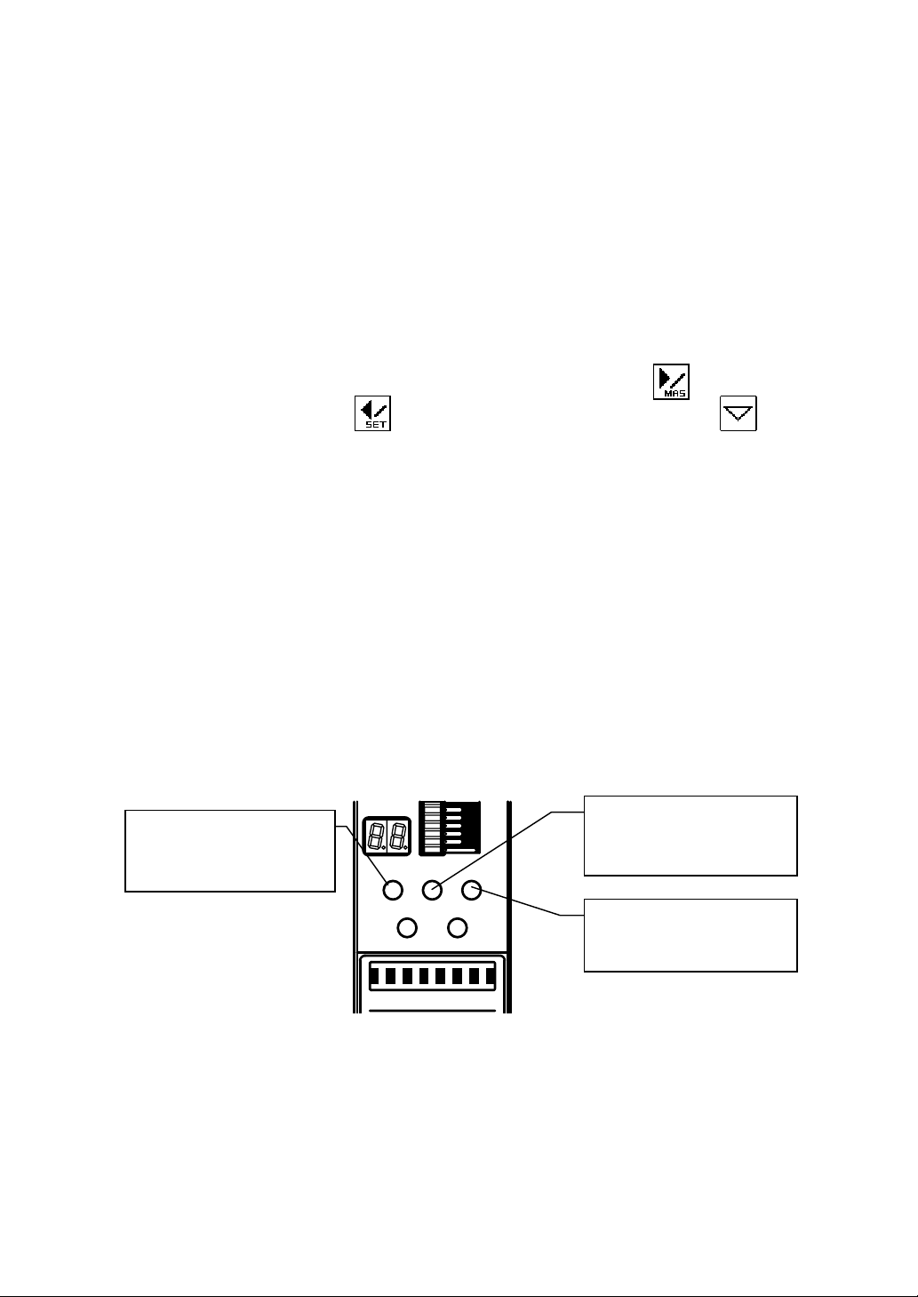
4. Names and Functions of Controls and Parts
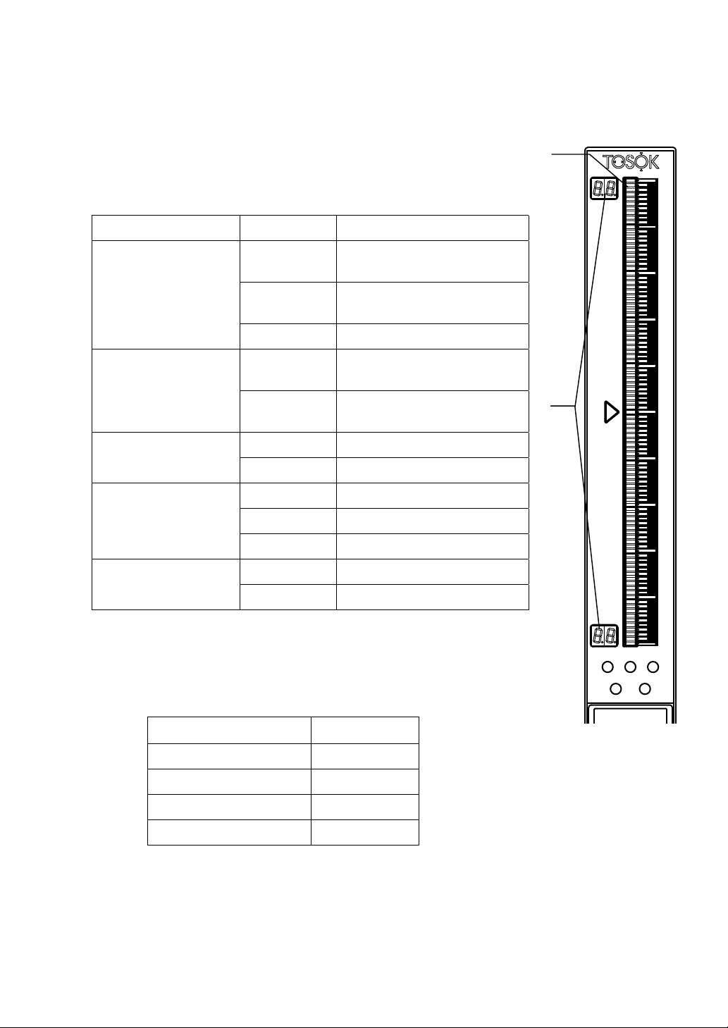
(1) Bargraph display
Indicates the measured value, judgment result, or other
types of information by a 101-dot, 3-color bar.
Table 4-1. Relationship between bar color and display description in
each mode.
Mode Bar color Display description
(1)
Measure
Hold measured value
Master
(2) Range displays
Indicate the bar top and bottom dimensions in two digits.
Green (light) Measured value (judgment
result OK)
Red (light) Measured value (judgment
result NG)
Orange (dot) Upper or lower limit value
Green (dark) Measured value (judgment
result OK)
Red (dark) Measured value (judgment
result NG)
Orange (light) Current set valueSet
Green (dot) Previous set value
Green (light) Mastering enabled condition
Red (light) Mastering disabled condition
Orange (dot) Mastering data
Orange (light) Measured valueAdjust detector
Green (dot) Mastering data
(2)
SET
213
MAS
Table 4-2. Range displays.
Measuring range (µm)
20 10.
50 25.
100 50.
200 10
Digital display
3
Page 6
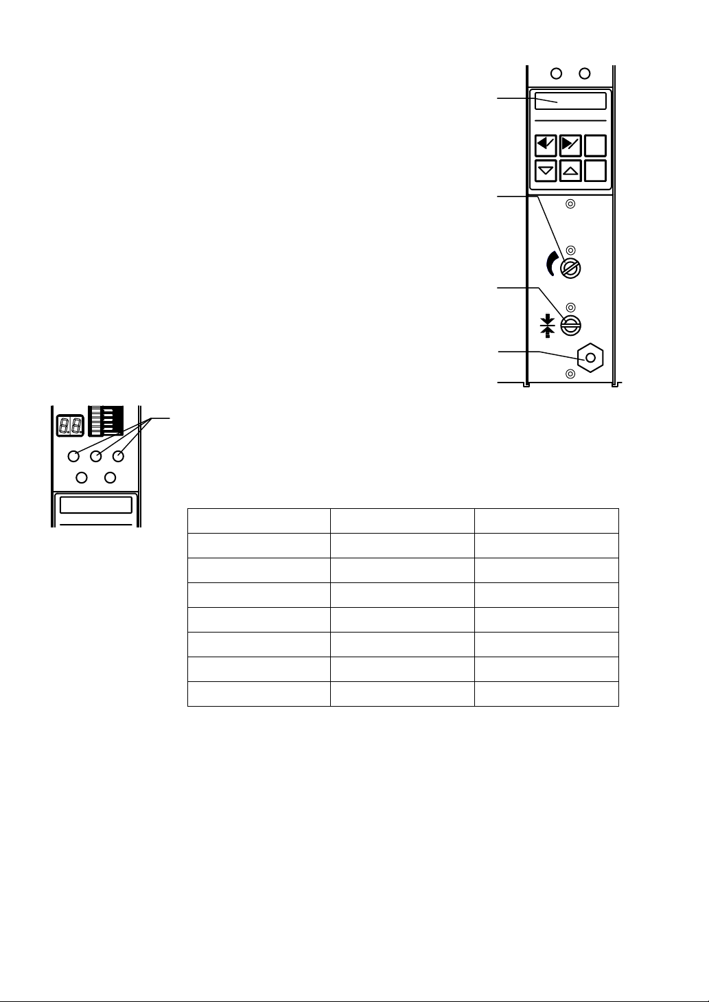
(3) Alphanumeric display
SETMA
S
Indicates the measured value, set value, set item, or other
types of information by 8-digit 7 × 5 dot characters.
(3)
(4) Sensitivity adjustment knob
Adjusts the sensitivity of the air circuit. This adjustment is
necessary only for changing the measuring nozzle and
correcting a mastering error.
(5) Zero adjustment knob
Adjusts the zero position of the air circuit. This adjustment
is necessary only for changing the measuring nozzle and
correcting a mastering error.
(6) Measuring nozzle port
Accepts the vinyl hose of the measuring nozzle.
(7) Item and judgment LEDs
SET
(7)
21
3
MAS
Indicate the judgment result. LED 1 comes on red when the
measured value is –NG, LED 2 comes on green when the
measured value is OK, and LED 3 comes on red when the
measured value is +NG.
Table 4-3. LED colors and conditions indicated.
Color Condition Mode
(4)
(5)
(6)
SET MAS
CAG
RST
ENT
2000
MAG
ZERO
GAGE
LED 1: Red (light) Judgment result –NG Measure
LED 2: Green (light) Judgment result OK Measure
LED 3: Red (light) Judgment result +NG Measure
LED 1: Red (dark) Judgment result –NG Hold measured value
LED 2: Green (dark) Judgment result OK Hold measured value
LED 3: Red (dark) Judgment result +NG Hold measured value
LED 1: Orange (light) Mastering Master
4
Page 7
SET
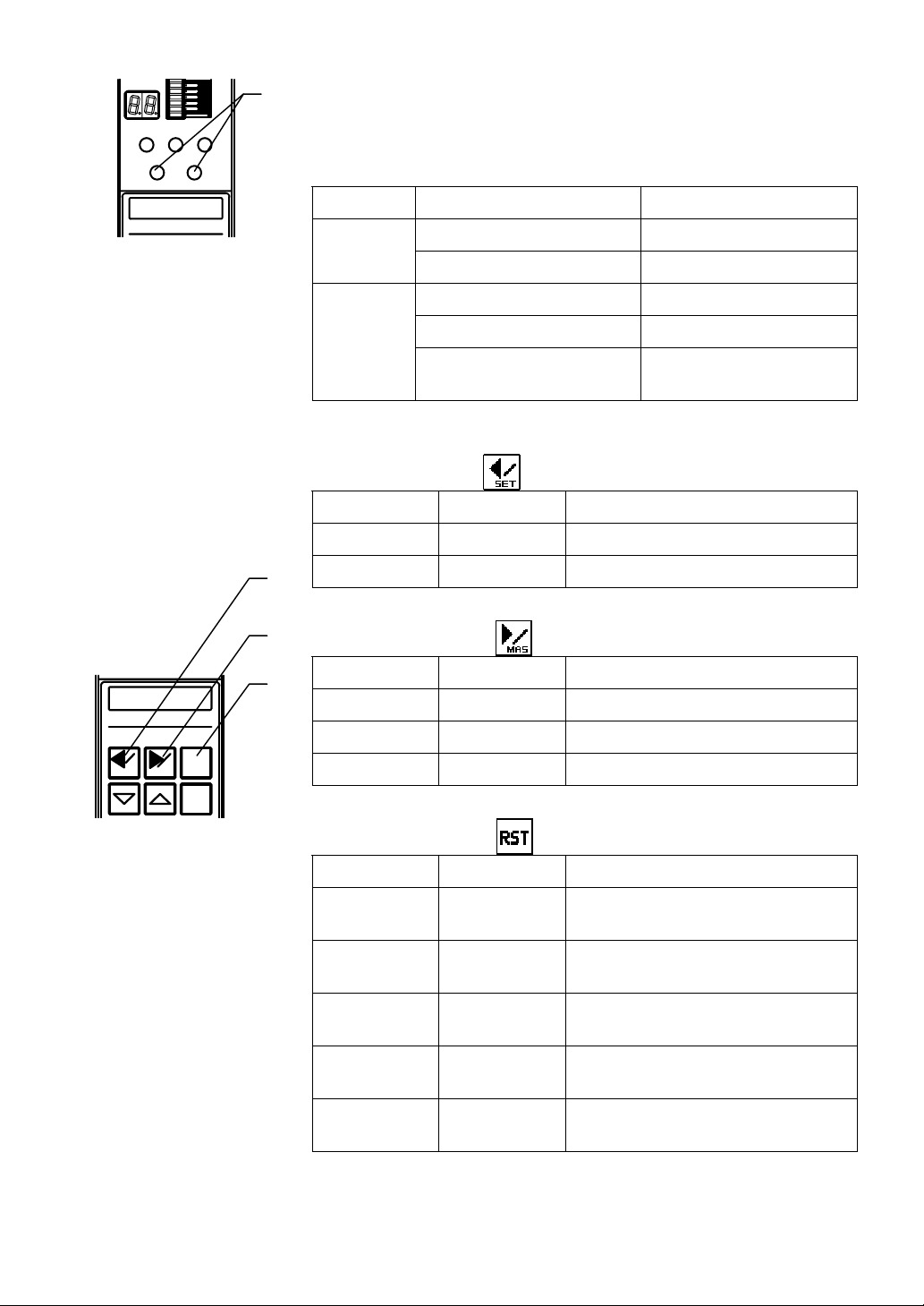
(8) Mode LEDs
(8)
21
3
MAS
Indicate the current mode and the mastering result. The
relationship between the LED color and the mode or mastering
result is as shown in Table 4-4.
Table 4-4. LED colors and conditions indicated.
LED name LED color Mode or condition
Orange Set modeSET
Green Change program mode
SET MAS
RST
ENT
MAS
Orange Master mode
Flashing red Mastering result NG
Alternately red and orange Master mode,
Mastering result NG
(9) Control keys
Left arrow key
Mode Keying Condition
Measure Press 2 sec. Mode is changed to set mode.
Set Press once. Set item can be selected.
Right arrow key
Mode Keying Condition
Measure Press 2 sec. Mode is changed to master mode.
Set Press once. Set item can be selected.
Master Press once. Display description is changed.
RST (reset) key
Mode Keying Condition
Hold measured
Press once. Measured value hold is cleared.
value
Set (set value
being entered)
Set (set item
being selected)
Press once. Set value is returned to previous
condition.
Press once. Setting can be finished (WRITE or
CANCEL).
Master Press once. Display description is returned to
previous condition.
Adjust detector Press once. Display description is returned to
previous condition.
5
Page 8
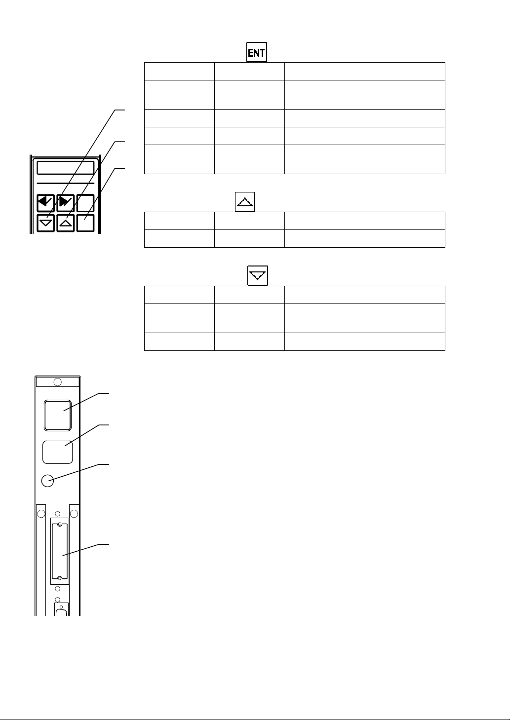
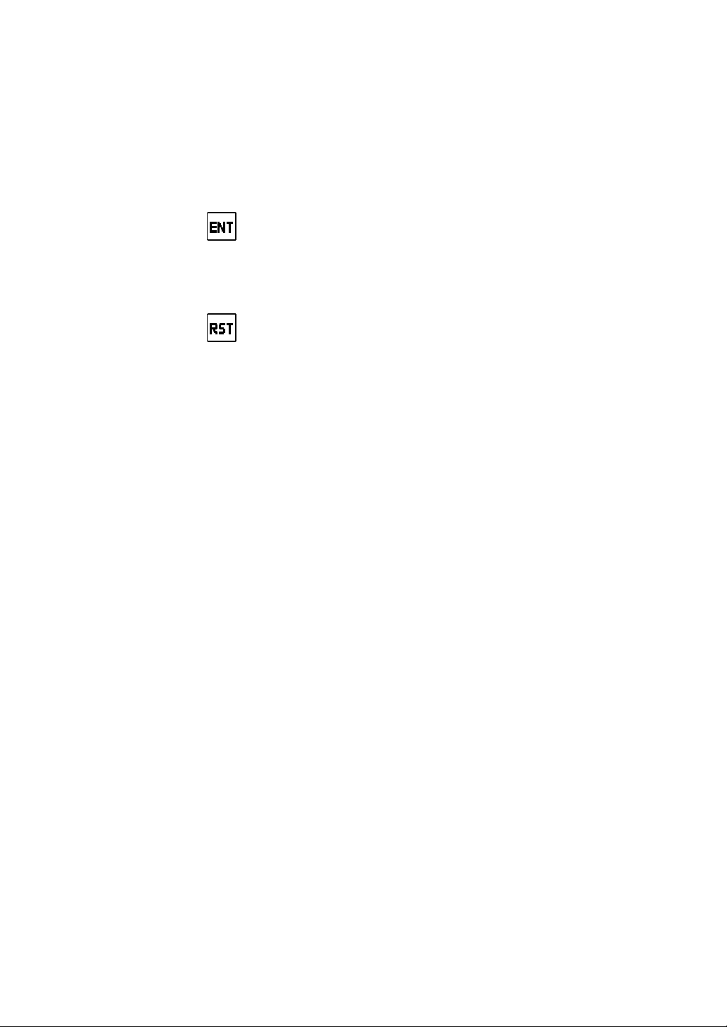
ENT (enter) key
Mode Keying Condition
Measure Press once. Measured value is held (when
mastering result is OK).
Set Press once. Set item and value are determined.
Master Press once. Master measured value is read.
Adjust
detector
Press once. Detector adjustment is finished.
SET MAS
AC85~264V
FUSE
3A
RST
ENT
(10)
(11)
(12)
Up arrow key
Mode Keying Condition
Set Press once. Set value is entered.
Down arrow key
Mode Keying Condition
Measure Press 2 sec. Mode is changed to change
program mode.
Set Press once. Set value is entered.
(10) Power connector (input) and power switch
Input AC power. Usable in the range of 85 to 264 VAC. Use
the accessory power cable in the range of 85 to 125 VAC.
(11) Power connector (output)
Accepts the power connector (input) of an adjacent instrument to
be used in combination, and is internally connected to the power
connector (input).
(12) Fuse holder
EXT I/O
(13)
A glass tube fuse (φ5.2 × 20, 3 A) is used.
(13) DC input/output connector (option)
Connector to be connected to an LED or sequencer, and used
2C
for input of measure, mastering and other commands and for
output of judgment result and BCD.
6
Page 9
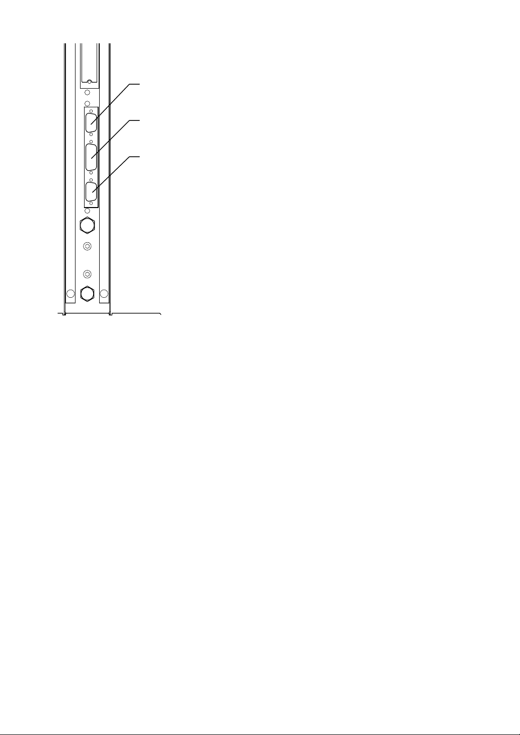
EXT I/RS232CSW.ETCANALOG
(14) RS232C connector
A serial communication connector for connecting a personal
computer or printer.
(14)
(15) Switch input connector
(15)
A connector for input of a measure or mastering command with
an external button. It is also used for RS422 communication
and Digimatic output (options).
(16)
(16) Analog input/output connector
A connector for external analog signal input and amplifier signal
output.
7
Page 10
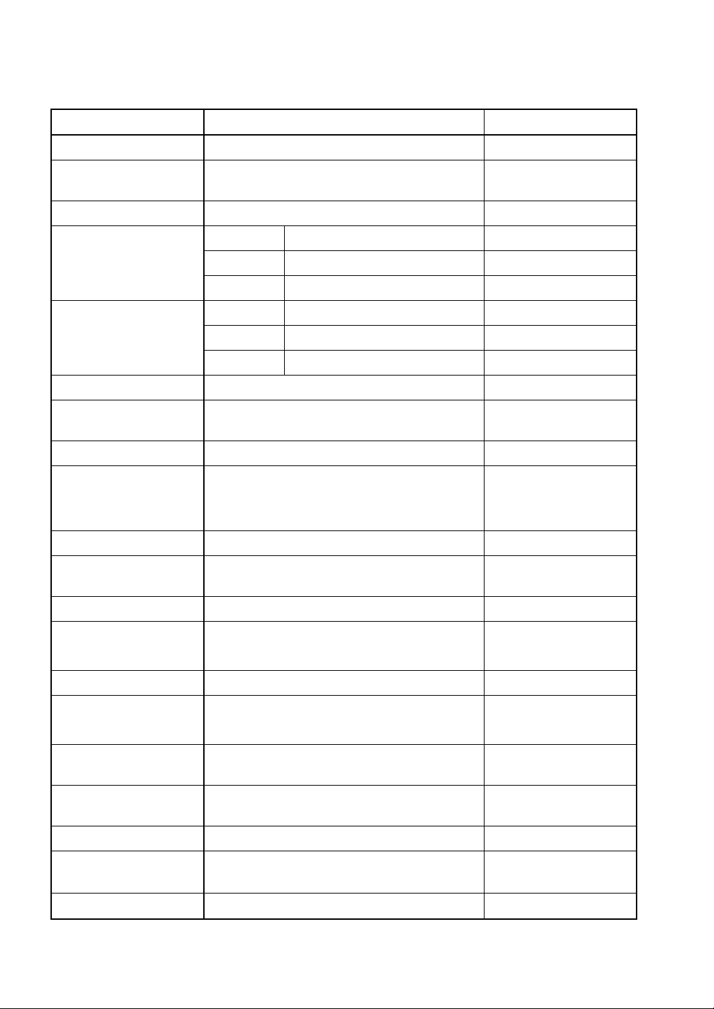
5. Specifications
Item Specification Remarks
Input 1 air channel
Air supply pressure 0.196 MPa Source pressure:
0.3 MPa or more
Measurement item 1
Measuring range (mm)
Resolution (mm)
Bargraph display 101 dots (red, green, orange, light/dark)
Bargraph display
method
Range display 2 digits (numbers), 2 places
Multifunctional display 8 digits (numbers/alphabet)
Shift range ±1000% (full scale) From Version 2.60
Actual dimension
display
Judgment result ±NG and OK
Judgment result
display
CAG2000 0.0200, 0.0500, 0.100, 0.200
CAG2000E 0.0250, 0.0500, 0.100, 0.200
CAG2000H 0.0100, 0.0200, 0.0500, 0.1000
CAG2000 0.0002, 0.0005, 0.001, 0.002
CAG2000E 0.00025, 0.0005, 0.001, 0.002
CAG2000H 0.0001, 0.0002, 0.0005, 0.0010
Bar (OK: Green, NG: Red), Dots (Max/Min)
Measured value, set item, set value, and
error display
000.0000 mm (7 digits + decimal point)
Bargraph display (color), judgment LEDs
Multifunctional display
Automatic mastering Minimum and maximum masters
Automatic mastering
range
Number of setting
programs
Power supply voltage
and frequency
Power supply capacity 30 VA
Dimensions and mass
Operating temperature
Zero position: ±50% (full scale)
Sensitivity: ±20% (full scale)
10
85 to 264 VAC, 50/60 Hz 100-VAC power cable
50 mm wide × 480 mm high × 200 mm deep,
4 kg
0 to 45°C
8
supplied as accessory
Page 11
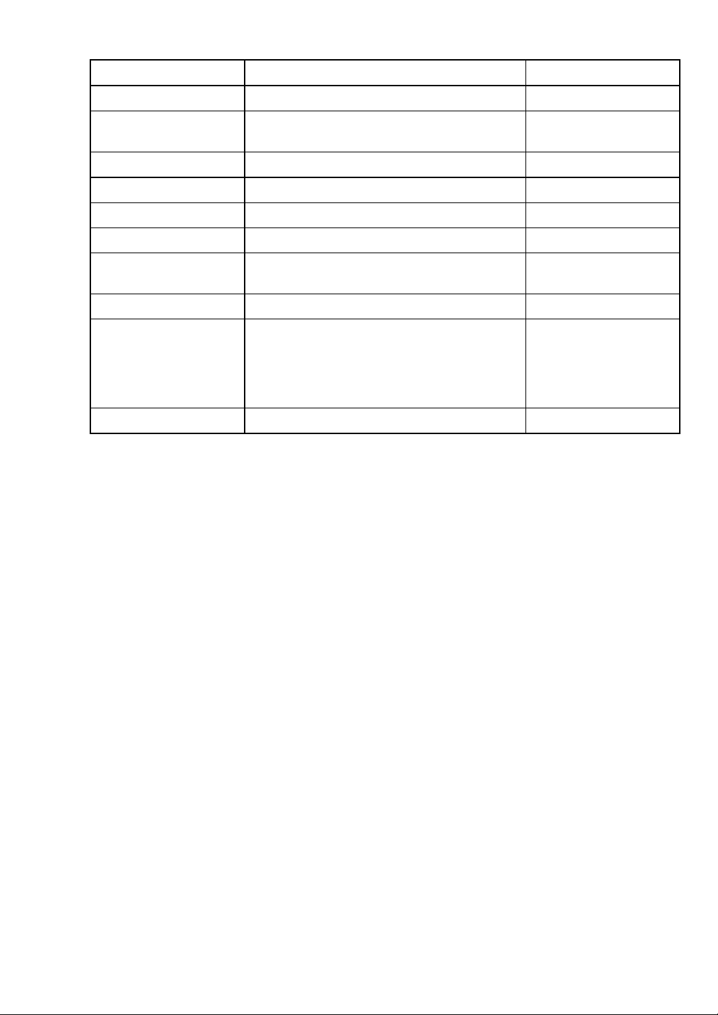
Standard
Item Specification Remarks
External input 4 (measure, reset, maximum master, and
minimum master)
Serial output 1 (printer or personal computer) RS232C
Optional
Printer output 1 (DP1) Digimatic
Judgment result output –NG, OK, +NG (12/24 VDC)
Rank output –NG,OK1 to OK14, +NG (12/24 VDC) Rank function
BCD output 1 (12/24 VDC)
Peak measurement
function
Rank function 99 ranks maximum OK range
+PEAK, –PEAK,
TIR (= +PEAK – (–PEAK)),
TIR (= +PEAK – (–PEAK) /2)
External buttons or foot
switch
combined use
Based on
measurement value
change with auto
measurement start
function
9
Page 12
6. Measurement
6.1 Preparation
Attach the regulator to the rear of the instrument, and connect it with the air filter.
Connect the measuring nozzle hose to the front of the instrument, and connect the
accessory power cable to the rear of the instrument.
Turn on the power switch (or press the position marked I of the switch) at the rear of
the instrument, so that the power of 85 to 264 VAC (50/60 Hz) will be supplied to the
instrument. Supply air at 0.3 to 0.7 MPa to the air filter.
When the instrument is started, it is in the measure mode. Press for 2 sec to
change to the master mode, for 2 sec to change to the set mode, and for 2
sec to change to the change program mode.
6.2 Measuring
Bargraph display, and item and judgment LEDs
(1) The judgment upper and lower limit values are indicated by orange (dark) on the
bargraph display.
(2) The bargraph display is illuminated green (light) and red (light) when the judgment
result is OK and NG, respectively.
(3) The item and judgment LEDs 1, 2 and 3 come on red, green and red when the
measured value is –NG, OK and +NG, respectively.
Comes on red when
measured value is –NG
Fig. 6-1. Item and judgment LEDs during measurement.
SET
21
3
MAS
Comes on green when
measured value is OK
Comes on red when
measured value is +NG
10
Page 13
Hold measured value mode
The measured value is held, except when the mastering result is NG.
(1) The bargraph display is usually in the measure mode and shows the value being
measured (this is called the free run condition). In the free run condition, the
measured value is indicated by green (light) on the bargraph display when it is OK
and by red (light) on the bargraph display when it is NG.
(2) Press in the free run condition to hold the measured value (this is called the
hold condition). In the hold condition, the measured value is indicated by green
(dark) on the bargraph display when it is OK and by red (dark) on the bargraph
display when it is NG.
(3) Press to clear the measured value hold.
11
Page 14
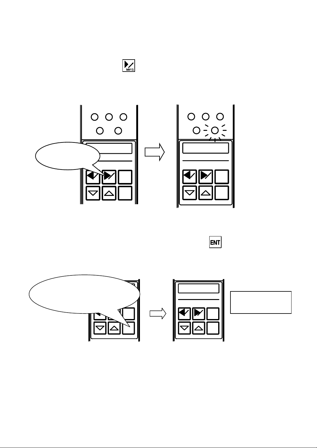
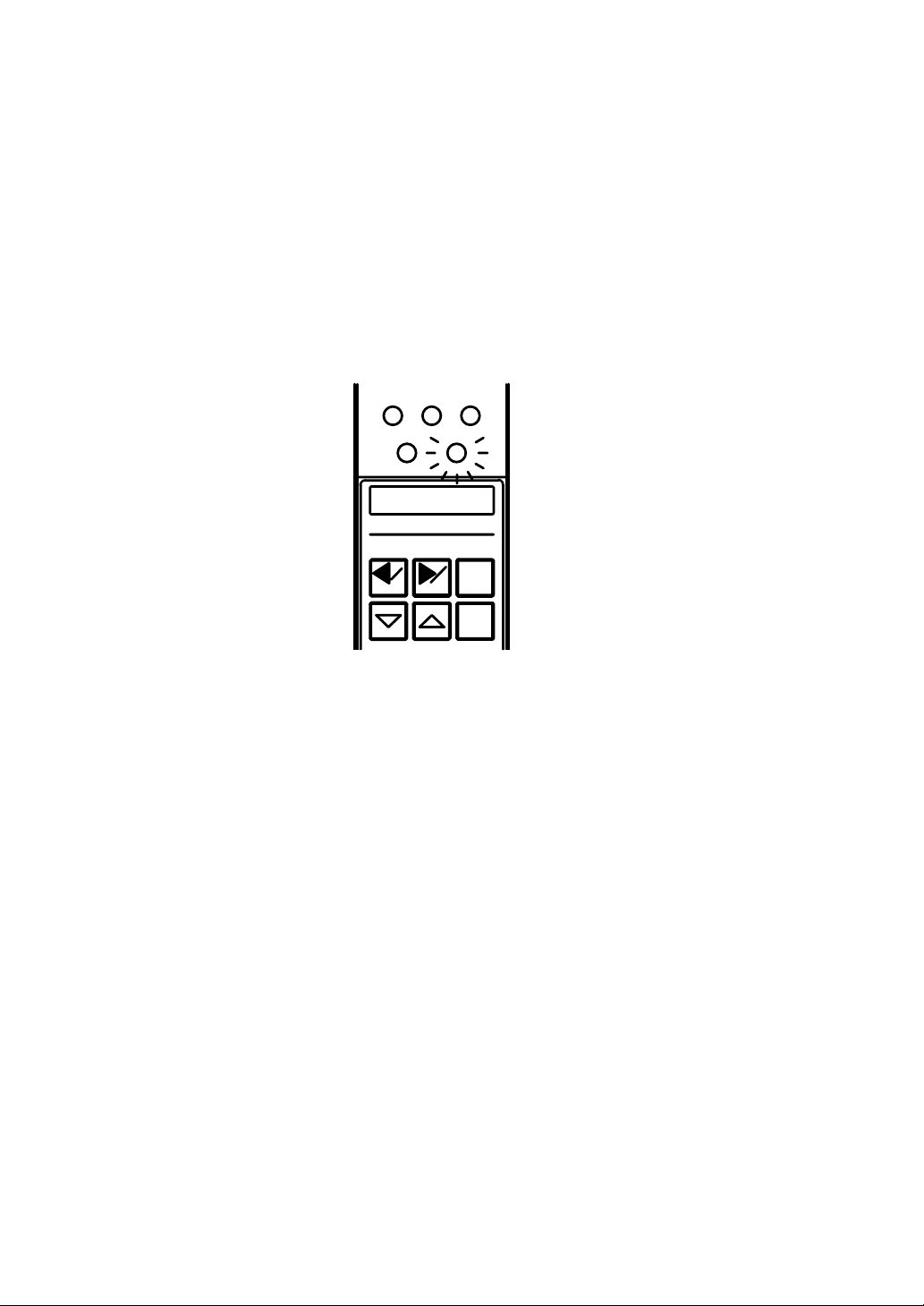
7. Mastering
7.1 Automatic mastering
In the measure mode, press for 2 sec or more.
The MAS LED below the bargraph display comes on orange, “MIN M.” appears on the
alphanumeric display, and the instrument changes to the master mode.
Measure mode Master mode
2
1
3
213
MAS
SET
Press 2 sec or
more
12.3
SET MAS
RST
SET MAS
ENT
Fig. 7-1. Changing to master mode.
Set the minimum master in the measuring nozzle, and press . The instrument is
calibrated with the minimum master, and “MAX M.” is shown on the alphanumeric
display.
Set minimum master in
measuring nozzle, and
press this
SET MAS
RST
MAX M.
SET MAS
SET
MIN M.
MAS
RST
ENT
Completion of
minimum-mastering
RST
ENT
Fig. 7-2. Calibrating with minimum master.
ENT
12
Page 15
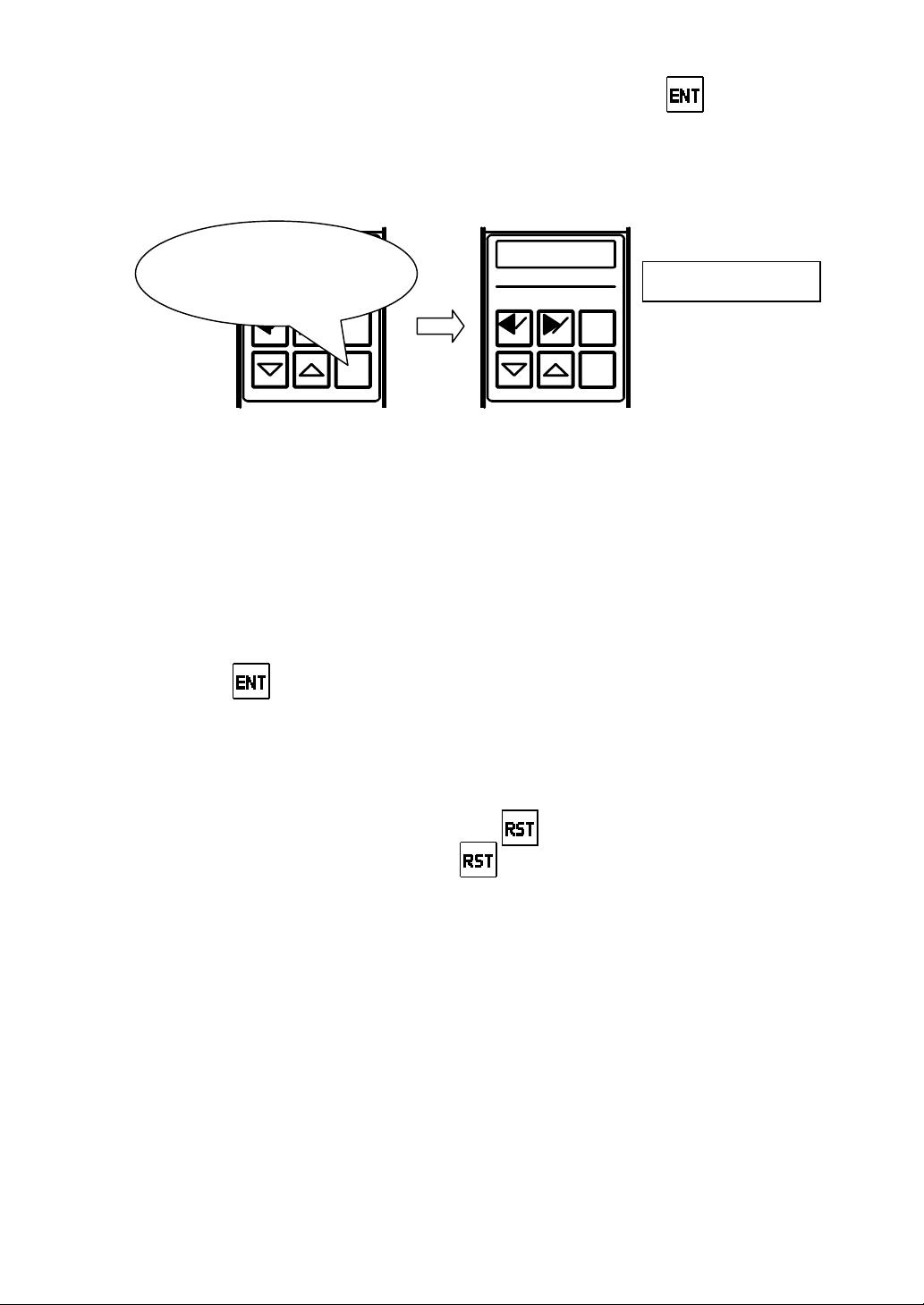
Set the maximum master in the measuring nozzle, and press . The instrument
is calibrated with the maximum master. If there is no mastering error, “MAS OK” is
shown for 2 sec on the alphanumeric display, and the instrument ends the master
mode and returns to the measure mode.
Set maximum master in
measuring nozzle, and
press this
SET MAS
RST
ENT
MAS OK
SET MAS
Mastering finished
RST
ENT
Fig. 7-3. Ending mastering.
If there is a mastering error, its description is shown on the alphanumeric display as
follows:
ERR ZERO: Zero position error (outside of automatic mastering range)
ERR MAG: Sensitivity error (outside of automatic mastering range)
ERR REV: Maximum and minimum master values reversed
ERR OFFR: Outside of measuring range
Press to return to step above. If it is necessary to adjust the zero position
and sensitivity of the air circuit with the zero and sensitivity adjustment knobs,
respectively, refer to “10. Adjusting Zero Position and Sensitivity with Zero and
Sensitivity Adjustment Knobs”.
In the middle of the master mode, press to return to the previous condition.
When “MIN M.” is displayed, press to return to the measure mode.
Mastering data storing function
The instrument is designed to read the last mastering data and fall in the master request
condition.
(1) Master request condition
When the power of the instrument is turned on or when a program change is made,
the instrument operates as follows:
13
Page 16
Flashing of MAS LED
The MAS LED flashes orange to indicate that the last mastering data is effective
for the currently selected program and flashes red to indicate that the last
mastering data is not effective for the currently selected program (or the mastering
data is cleared).
Indication on alphanumeric display
“MAS REQ” is shown on the alphanumeric display.
Judgment result output signal (when judgment result output option is added)
The judgment result output signal “MAS OK” is turned off.
213
MAS
SET
MAS REQ
SET MAS
RST
ENT
Fig. 7-4. Master request condition.
(2) Procedure for coping with master request condition
Calibrate the instrument with the masters.
When the MAS LED is flashing orange, the mastering operation can be omitted by
any of steps to below.
Press one of the control keys.
Input a reset command from an external signal or with an external button.
Input a clear master request command through the serial communication
(RS232C). (Refer to “11.1 Serial output”.)
These steps to clear the condition described in in (1) above when the MAS
LED is flashing red, and clear the conditions described in to in (1) above when
the MAS LED is flashing orange.
14
Page 17

7.2 Clearing mastering data
In the measure mode, press for 2 sec or more.
When the MAS LED below the bargraph display is turned on and “MAX M.” or
“MIN M.” is shown on the alphanumeric display (refer to Fig. 7-1), press to
change to the adjust detector mode and show “ADJ.” on the alphanumeric display.
Press to change to the clear mastering data mode and show “MAST CLS”
on the alphanumeric display.
Press to clear the mastering data, show “M. CLS OK” on the alphanumeric
display, and return to the master mode.
SET
SET MAS
Press
213
MAS
ADJ.
RST
ENT
213
MAS
SET
MAST CLS
Press
SET MAS
Fig. 7-5. Clearing mastering data.
RST
ENT
213
MAS
SET
M .CLS OK
SET MAS
RST
ENT
15
Page 18

8. Changing Programs
In the measure mode, press for 2 sec or more.
The SET LED below the bargraph display comes on green, “PROG” appears on
the alphanumeric display, and the instrument changes to the change program
mode.
Measure mode Change program mode
213
SET
PROG
MAS
Press 2 sec
SET
213
MAS
10.0
or more
SET MAS
RST
ENT
SET MAS
RST
ENT
Fig. 8-1. Changing to change program mode.
With “PROG” shown on the alphanumeric display, press . The current
program number is shown on the alphanumeric display.
SET
213
MAS
SET
213
MAS
PROG
2
Press
SET MAS
RST
ENT
SET MAS
Fig. 8-2. Display of current program number.
16
RST
ENT
Page 19

Press or to select the number of the program to be used, and press
r
to determine the selection. The instrument ends the change program mode
and returns to the measure mode.
SET
213
MAS
12.0
213
Decrements
program numbe
SET
2
MAS
SET
213
MAS
7
Increments
program number
Determines
selection
SET MAS
RST
ENT
SET MAS
RST
ENT
SET MAS
RST
ENT
Fig. 8-3. Selecting and determining program number.
X A program number change calls for mastering. A measuring nozzle change may
call for the zero position and sensitivity of the air circuit to be adjusted with the zero
and sensitivity adjustment knobs, respectively.
X When setting any item, select the number of the program to be used before
changing to the set mode.
X When its power is turned on, the instrument starts at the program number selected
last.
17
Page 20

9. Setting
–
Setting relevant items is required for each program to be used. After a program change,
set necessary items. (Refer to “8. Changing Programs”.)
(1) Setting polarity
In the measure mode, press
bargraph display comes on orange, “POL” appears on the alphanumeric display,
and the instrument changes to the set mode.
Measure mode Set mode
213
MAS
SET
10.0
Press 2 sec
or more
SET MAS
Press to show the current polarity on the alphanumeric display, and press
or to change between “+ (ID measurement)” and “– (OD measurement)”.
RST
ENT
Fig. 9-1. Changing to set mode.
for 2 sec or more. The SET LED below the
213
MAS
SET
POL
SET MAS
RST
ENT
213
SET
POL
Press
SET MAS
MAS
Changes
between + and
RST
ENT
Fig. 9-2. Changing polarity.
213
SET
+
SET MAS
MAS
Changes
between + and –
RST
ENT
18
Page 21

Press to determine the selected polarity. The next step is setting the
measuring range, and “RANGE” is shown on the alphanumeric display.
SET
213
MAS
+
213
MAS
SET
RANGE
Determines polarity
SET MAS
RST
ENT
SET MAS
RST
ENT
Fig. 9-3. Determining polarity.
(2) Setting measuring range
Changing the measuring range may call for the A/E converter to be switched over.
When changing the measuring range between 50 and 100 µm, the A/E converter
need not be switched over, but the instrument must be adjusted as described in “10.
Adjusting Zero Position and Sensitivity with Zero and Sensitivity Adjustment Knobs”.
In other cases, contact NIDEC TOSOK.
With “RANGE” shown on the alphanumeric display, press . The current
measuring range is shown. Press or to change the measuring range
to 20, 50, 100, or 200 µm.
SET
RANGE
Press
SET MAS
213
MAS
Changes
measuring range
RST
ENT
213
SET
50
SET MAS
MAS
Changes
measuring range
RST
ENT
Fig. 9-4. Changing measuring range.
19
Page 22

Press to determine the selected measuring range. The next step is setting
the shift value, and “SHIFT” is shown on the alphanumeric display.
SET
213
MAS
100
SET
SHIFT
213
MAS
Determines
measuring range
SET MAS
RST
ENT
SET MAS
RST
ENT
Fig. 9-5. Determining measuring range.
(3) Setting shift value
In the case of a one-side tolerance, for example, the measured value is shown at the
center of the bargraph display. When not using this function, set the shift value at 0.
With “SHIFT” shown on the alphanumeric display, press . The current
notation unit is shown. Press or to change to the tolerance notation
in µm or the nominal notation in mm. Press to determine the selected
notation.
213
SET
SHIFT
Press
SET MAS
MAS
RST
ENT
213
MAS
SET
MM
Changes
notation unit
SET MAS
Changes
notation unit
RST
ENT
Fig. 9-6. Changing notation unit.
20
213
MAS
SET
MICRO
Determines
notation unit
SET MAS
RST
ENT
Page 23

When the tolerance notation is selected, press or to enter the shift
value. When the nominal notation is selected, press or to change
the digit to be set, and press or to enter the shift value. Usually,
enter the median value of the tolerances as the shift value.
SET
213
MAS
0.000
SET
213
MAS
0.000
SET
213
MAS
2.000
Enters shift
value
SET MAS
RST
SET MAS
RST
Enters shift
SET MAS
RST
value
Changes digit
ENT
ENT
ENT
Changes digit
Fig. 9-7. Entering shift value (for nominal notation).
Press to determine the entered shift value. The next step is setting the
judgment upper limit value, and “MAX” is shown on the alphanumeric display.
SET
213
MAS
SET
213
MAS
9.045
Determines
shift value
SET MAS
Fig. 9-8. Determining shift value.
RST
ENT
21
MAX
SET MAS
RST
ENT
Page 24

(4) Setting judgment upper limit value
With “MAX” shown on the alphanumeric display, press . The current
judgment upper limit value is shown. Press or to enter the new
judgment upper limit value.
SET
213
MAS
MAX
SET
213
MAS
9.085
Decrements
Press
SET MAS
RST
ENT
judgment upper
limit value
SET MAS
Increments
RST
judgment upper
limit value
ENT
Fig. 9-9. Entering judgment upper limit value.
Press to determine the new judgment upper limit value. The next step is
setting the judgment lower limit value, and “MIN” is shown on the alphanumeric
display.
SET
213
MAS
SET
213
MAS
9.065
MIN
Determines
SET MAS
RST
ENT
SET MAS
RST
ENT
Fig. 9-10. Determining judgment upper limit value.
22
Page 25

(5) Setting judgment lower limit value
With “MIN” shown on the alphanumeric display, press . The current
judgment lower limit value is shown. Press or to enter the new
judgment lower limit value.
SET
213
MAS
MIN
SET
213
MAS
9.005
Decrements
judgment lower
limit value
SET MAS
Press
RST
ENT
SET MAS
RST
Increments
ENT
judgment lower
Fig. 9-11. Entering judgment lower limit value.
Press to determine the new judgment lower limit value. The next step is
setting the maximum master value, and “MAX M.” is shown on the alphanumeric
display.
SET
213
MAS
SET
213
MAS
9.025
Determines
SET MAS
RST
MAX M.
SET MAS
ENT
Fig. 9-12. Determining judgment lower limit value.
23
RST
ENT
Page 26

(6) Setting maximum master value
With “MAX M.” shown on the alphanumeric display, press . The current
maximum master value is shown. Press or to enter the new
maximum master value.
213
SET
MAX M.
Press
SET MAS
MAS
Decrements
maximum
RST
ENT
213
SET
9.085
SET MAS
MAS
Increments
maximum
master value
RST
ENT
Fig. 9-13. Entering maximum master value.
Press to determine the new maximum master value. The next step is
setting the minimum master value, and “MIN M.” is shown on the alphanumeric
display.
SET
213
MAS
SET
213
MAS
9.065
Determines
SET MAS
RST
ENT
SET MAS
RST
ENT
Fig. 9-14. Determining maximum master value.
When the maximum master value is equal to or smaller than the minimum master
value, “ERR MAS” is shown on the alphanumeric display, the set value returns to
the previous value, and the instrument returns to the condition in step above.
Again enter the new maximum master value.
24
Page 27

(7) Setting minimum master value
With “MIN M.” shown on the alphanumeric display, press . The current
minimum master value is shown. Press or to enter the new minimum
master value.
213
SET
MIN M.
Press
SET MAS
MAS
RST
ENT
Decrements
minimum
master value
213
SET
9.005
SET MAS
MAS
Increments
minimum
RST
master value
ENT
Fig. 9-15. Entering minimum master value.
Press to determine the new minimum master value. The next step is
storing the set values, and “END” is shown on the alphanumeric display.
SET
213
MAS
SET
213
MAS
9.025
Determines
SET MAS
RST
ENT
END
SET MAS
RST
ENT
Fig. 9-16. Determining minimum master value.
When the minimum master value is equal to or greater than the maximum master
value, “ERR MAS” is shown on the alphanumeric display, the set value returns to
the previous value, and the instrument returns to the condition in step above.
Again enter the new minimum master value.
25
Page 28

(8) Storing set values (described in Items (1) to (7) above)
CANC
9.030
When the setting of the minimum master value is finished as the last step of the
setting procedure, “END” is shown on the alphanumeric display. When is
pressed in the middle of the set mode, “END” is also shown. Press to show
“WRITE” on the alphanumeric display.
SET
Press
SET MAS
213
MAS
END
RST
ENT
213
SET
WRITE
SET MAS
MAS
RST
ENT
Fig. 9-17. Ending setting.
Press or to select “WRITE” or “CANCEL”, and press to
determine the selection. When “WRITE” is selected, the current set values are
stored. When “CANCEL” is selected, the current set values are canceled, and
the previous set values are made effective. After this determination, the
instrument ends the set mode and returns to the measure mode.
SET
Changes
SET MAS
213
MAS
EL
Changes
RST
ENT
213
MAS
SET
WRITE
Determines
SET MAS
Fig. 9-18. Storing set values.
RST
ENT
26
Measure mode
213
MAS
SET
SET MAS
RST
ENT
Page 29

10. Adjusting Zero Position and Sensitivity with Zero
and Sensitivity Adjustment Knobs
The zero position and sensitivity of the air circuit need not be adjusted, except after a
measuring head change or after the output of the mastering result NG due to wear.
10.1 Adjusting
In the measure mode, press for 2 sec or more.
The MAS LED below the bargraph display comes on, and “MAX M.” or “MIN M.”
appears on the alphanumeric display. Press to change to the adjust
detector mode. The alphanumeric display shows “ADJ.” for 2 sec and then the
measured value.
213
MAS
SET
12.3
Press 2 sec or more
SET MAS
RST
ENT
213
MAS
SET
MIN M.
SET MAS
Press
Fig. 10-1. Changing to adjust detector mode.
RST
ENT
213
SET
ADJ.
SET MAS
MAS
RST
ENT
27
Page 30

Press to double the indicating range of the bargraph display and show the
measured value on the bargraph and alphanumeric displays.
Maximum
master value
(green)
Minimum
master value
(green)
Press
1
2
3
MAS
SET
10.0
Fig. 10-2. Doubling indicating range.
1
SET
2
10
Maximum
master value
Minimum
master value
3
MAS
28
Page 31

Set the minimum master in the measuring head, and turn the zero adjustment
knob to set the indication at the minimum master value.
SET MAS
RST
ENT
Set indication at
CAG
2000
minimum master
value
Set minimum master
in measuring head
MAG
and turn knob
1
2
ZERO
SET
GAGE
3
MAS
Fig. 10-3. Adjusting zero position.
Set the maximum master in the measuring head. If the indication is about the
maximum master value, the adjustment is finished.
Adjustment
finished
Fig. 10-4. Finishing adjustment with zero and sensitivity adjustment knobs.
When the indication is not in the automatic mastering range (or the bargraph
display is illuminated red), refer to “10.2 Indication below mastering range” on
page 31 or “10.3 Indication above mastering range” on page 32.
29
Page 32

After the adjustment is finished, press to change to the master mode and
show “MIN M.” on the alphanumeric display. For automatic mastering, refer to “7.
Mastering”.
213
SET
MAS
12.0
Press
SET MAS
When returning to the measure mode without automatic mastering, press .
Master mode Measure mode
SET
RST
ENT
Fig. 10-5. Changing to master mode.
213
MAS
213
SET
MAS
MIN M.
SET MAS
213
SET
MAS
RST
ENT
12.3
SET MAS
Fig. 10-6. Returning to measure mode.
RST
ENT
SET MAS
30
12.3
Press
RST
ENT
Page 33

10.2 Indication below mastering range
–
(1) When the indication does not reach the mastering range, the instrument is insufficient
in sensitivity. With the maximum master set in the measuring head, turn the
sensitivity adjustment knob clockwise so that the indication exceeds the maximum
master value by about 5 times the insufficiency from the maximum master value.
(2) Turn the zero adjustment knob clockwise to set the zero position at the maximum
master value.
Maximum
master value
Insufficiency
of 30 µm
Insufficiency × 5 + Maximum master value
= 30 × 5 + 20
= 170
However, alphanumeric display cannot
show more than 100
1
2
SET MAS
10
CAG
RST
ENT
2000
MAG
Z
ERO
GAGE
SET MAS
Turn to bring
indication to
SET MAS
3
Turn to bring
indication to 100
maximum master
CAG
RST
ENT
2000
MAG
ZERO
GAGE
value
Fig. 10-7. Adjusting for indication below mastering range.
(3) Set the minimum master in the measuring head. When the indication is about the
minimum master value, the adjustment is finished.
When the indication is not about the minimum master value, turn the zero adjustment
knob to bring the indication to the minimum master value. Set the maximum master
in the measuring head. If the indication does not come to about the maximum
master value, repeat steps (1) and (2) in 10.2 or 10.3.
31
Page 34

10.3 Indication above mastering range
(1) When the indication is above the mastering range, the instrument is excessive in
sensitivity. With the maximum master set in the measuring head, turn the sensitivity
adjustment knob counterclockwise so that the indication is returned from the
maximum master value by about 5 times the excess from the maximum master
value.
(2) Turn the zero adjustment knob counterclockwise to set the zero position at the
maximum master value.
Excess of
22 µm
1
2
SET MAS
Maximum master value – (Excess × 5)
= 20 – (22 × 5)
= –90
Maximum
master value
3
CAG
RST
ENT
2000
MAG
ZERO
GAGE
SET MAS
Turn to bring
indication to –90
CAG
RST
ENT
2000
MAG
ZERO
GAGE
SET MAS
Turn to bring indication
to maximum master
value
42
Fig. 10-8. Adjusting for indication above mastering range.
32
Page 35

(3) Set the minimum master in the measuring head. When the indication is about the
minimum master value, the adjustment is finished.
When the indication is not about the minimum master value, turn the zero adjustment
knob to bring the indication to the minimum master value. Set the maximum master
in the measuring head. If the indication does not come to about the maximum
master value, repeat steps (1) and (2) in 10.2 or 10.3.
33
Page 36

11. I/O Description
11.1 Serial output (RS232C)
(1) Description
This instrument can output the measured values to a printer and communicate with a
personal computer through RS232C.
Command Symbol
Hold measured value E
Clear measured value hold
Clear master request
Request measured value D
Minimum-mastering N
Maximum-mastering X
Change to Program 1 P01
Change to Program 4 P04
(2) Preparation
The RS232C connector at the rear of the instrument is provided for the personal
computer or printer. Connect the D-sub 9-pin (male) plug of an optional
communication cable to the RS232C connector. Three types of optional
communication cables are available for specific applications. For details, refer to
“13. Options”.
(3) Setting serial port
R
Baud rate: 9600
Bits/character: 8
Stop bit: 1
Start bit: 1
Parity bit: None
34
Page 37

(4) Transmitting measured values
Commands to instrument
Command Data type Symbol
Data transmitted to personal computer
Character string EHold measured value
ASCII 45H
Character string RClear measured value hold
ASCII 52H
Character string DRequest measured value
ASCII 44H
Measured value SP
*SP represents a space character.
In the measure mode, press . The measured value is held and transmitted
to the personal computer. The data transmission is disabled when the mastering
result is NG.
Judgment
result
20 0D 0A
CR LF
35
Page 38

(5) Automatic mastering
The master request condition can be cleared, and the instrument can be calibrated
with the minimum and maximum masters.
Commands to instrument
Command Data type Symbol
Character string RClear master request
ASCII 52H
Character string NMinimum-mastering
ASCII 4EH
Character string XMaximum-mastering
ASCII 58H
Calibrate the instrument with the minimum and maximum masters in that order.
Data transmitted to personal computer
When automatic mastering is performed through the serial communication, one of
the data shown in the table below is returned back.
Instrument condition Data type Externally returned data
Character string @ 0 O K SP SP SP M A S SP SP SP CR LFMastering result OK
ASCII (hex) 40304F4B2020204D41532020200D0A
Character string @ 0 E R R 0 1 Z E R O M 1 CR LFZero position
ASCII (hex) 403045525230315A45524F4D310D0A
Character string @ 0 E R R 0 4 G A I N M 1 CR LFSensitivity
ASCII (hex) 403045525230344741494E4D310D0A
Character string @ 0 E R R 0 7 R E V SP M 1 CR LFMasters reversed
Mastering error
Other than above
ASCII (hex) 40304552523037524556204D310D0A
Character string @ 0 E R R 1 0 O F F R M 1 CR LF
ASCII (hex) 403045525231304F4646524D310D0A
*SP represents a space character.
36
Page 39

(6) Changing programs
A change can be made to programs 0 to 9.
Commands to instrument
Command Data type Symbol
Character string P 0 1Change to program 1
ASCII 50H 30H 31H
Character string P 0 4Change to program 4
ASCII 50H 30H 34H
Data transmitted to personal computer
When a program change is made through the serial communication, one of the
data shown in the table below is returned back.
Instrument condition Data type Externally returned data
Change to program 1
finished
finished
Character string @ 0 P R O G 1 CR LF
ASCII 40H 30H 50H 52H 4FH 47H 31H 20H 20H 20H 20H 20H 20H 0DH 0AH
Character string @ 0 P R O G 2 CR LFChange to program 4
ASCII 40H 30H 50H 52H 4FH 47H 32H 20H 20H 20H 20H 20H 20H 0DH 0AH
37
Page 40

(7) Changing program and mastering timing charts
The commands cannot be executed in combination, but must be executed
individually.
(I: Transmission to CAG/CEG2000, O: Reception from CAG/CEG2000)
I: Change program
0.2 sec or less
O: Return 1
→←
I: Minimum-mastering
0.2 sec or less
O: Return 2
→←
I: Maximum-mastering
O: Return 3
0.2 sec or less
→←
I: Clear master request
O: Return 2
0.2 sec or less
→←
38
Page 41

11.2 External input
(1) Description
Using external buttons and a foot switch, the instrument can:
Measure a work.
Reset itself.
Be calibrated with the minimum master.
Be calibrated with the maximum master.
Note: Do not use the instrument through relay contact input.
(2) Preparation
The SW. ETC connector at the rear of the instrument is provided for external buttons.
It accepts a D-sub 15-pin (male) plug.
(3) Connector pin arrangement
Description No.
1
2
3
4
5
GND 6
Measure button 7
RESET button 8
Fig. 11-1. Pin arrangement diagram of SW. ETC connector at rear of instrument.
(4) Operation with external buttons
Measure button
(a) In the measure mode, press the measure button.
(b) The measured value is held. (This is called the hold measured value
condition.)
Note: The measured value cannot be held when the mastering result is NG.
RESET button
No. Description
9 Maximum master button
10 Minimum master button
11
12
13
14
15
Clears the measured value hold.
39
Page 42

Minimum master button
(a) In the measure mode, set the minimum master in the measuring nozzle.
(b) When the bargraph display is stabilized, press the minimum master button.
(c) The instrument is calibrated with the minimum master and readied for
calibrating itself with the maximum master (this is called the maximum-
mastering ready condition).
Maximum master button
(a) In the maximum-mastering ready condition, set the maximum master in the
measuring nozzle.
(b) When the bargraph display is stabilized, press the maximum master button.
(c) The instrument is calibrated with the maximum master and returns to the
measure mode.
(d) When a mastering error occurs (refer to step in “7.1 Automatic mastering”),
use the control keys on the instrument to clear the mastering error.
40
Page 43

12. Model Identification
CAG 20 00 –2 –DP
External input/output
None: Standard
DP: Digimatic output
DC: Judgment result output
DR: Rank output
BC: BCD output
A/E input
None: 1 channel
2: 2 channels
Measuring range
02: 20 µm
05: 50 µm
10: 100 µm
20: 200 µm (option)
Model number
20
Basic model designation
CAG
41
Page 44

13. Options
(1) Instrument
Measuring range : 200 µm
— Effective measuring range: 160 µm (with linear compensation)
Digimatic output: Output to printer (DP1), for example
Judgment result output : 12/24 VDC
Rank output : 12/24 VDC
BCD output : 12/24 VDC
(2) Separately sold parts
Filter (CAG2000-OP-AF): Air filter + Mist separator
Filter (CAG2000-OP-AFA): Air filter + Mist separator (with automatic drain)
Regulator (CAG2000-OP-AR): Precision regulator
Communication cable (CAG2000-OP-CB-1): D-sub 9-pin connector (EIA-232) for
Communication cable (CAG2000-OP-CB-2): D-sub 25-pin connector (EIA-574) for
personal computer
personal computer
Communication cable (CAG2000-OP-CB-3): D-sub 25-pin connector (EIA-574) for
printer
42
Page 45

14. Maintenance
(1) The air filter is clogged as it is used for a long period of time. Change the air filter
element after two years of use or when the pressure drop reaches 0.1 MPa.
(2) Cleaning A/E converter
When the A/E converter is used for a long period of time, oil and dust may
accumulate in the air circuit. Clean the A/E converter as described below.
Record the approximate installation position of the zero and sensitivity adjustment
knobs at the front of the instrument (or the distance of each knob from the edge).
This record facilitates mastering after cleaning.
Turn the zero and sensitivity adjustment knobs counterclockwise, and remove
them from the instrument.
Check the O-ring of each needle. If the O-ring is damaged, change it.
If the needle is dirty, clean it. Dampen a cotton swab with alcohol, and use it to
clean the φ3 mm hole into which the needle enters.
Replace the needle in each knob. If the split screw is loose, expand it with the tip
of a flat-end screwdriver. Take care not to overbend the split screw.
Turn the needle of each knob clockwise, and install the knobs in the original
position recorded at first. Adjust the zero position and sensitivity of the air circuit
with the zero and sensitivity adjustment knobs, respectively, and calibrate the
instrument with the minimum and maximum masters.
43
Page 46

15. Troubleshooting
Phenomenon Cause Remedy
Repeatability is not stable.
Zero adjustment knob is
ineffective.
Bargraph display does not
operate.
Air supply pressure is not
stable.
Regulator is
malfunctioning.
Measuring nozzle is worn. Change it.
Piping and joints are
leaking.
Entry of moisture or oil
causes trouble to
instrument.
Air supply pressure is too
low or high.
Piping and joints are
leaking.
Gap of measuring nozzle
is too small.
Gap of measuring nozzle
is too large.
Specified power is not
supplied.
Set regulator source
pressure at 300 kPa or
more.
Overhaul or change it.
Check for leakage, and
retighten.
Clean instrument.
Set regulator at 196 kPa.
Check for leakage, and
retighten.
Adjust to proper gap.
Adjust to proper gap.
Supply power of 85 to 264
VAC.
Bargraph and alphanumeric
displays are not illuminated.
Zero position of air circuit
is improperly adjusted.
Instrument is in hold
measured value mode.
Bargraph display is
illuminated green or red
(dark).
Instrument is in set mode. End set mode.
Power is not supplied. Supply power of 85 to 264
Fuse is blown. Change it.
Power supply or internal
circuit is faulty.
Calibrate instrument with
masters.
Press to clear this
condition.
VAC.
Ask NIDEC TOSOK for
repair.
44
Page 47

16. Cautions
(1) Air supply
Supply clean air free from dust, moisture, and oil. Drain the air filter once per day or
more frequently.
(2) Power cable
The power cable supplied as standard accessory is for 100 V. If you use supply
voltage in excess of 125 V, separately prepare a 250-V power cable.
(3) Control keys
Never operate the control keys with a sharp-pointed tool or the like.
(4) Export
When you try to export this instrument overseas, you may have to have the export
approved by the Ministry of Economy, Trade and Industry under the Export Trade
Control Ordinance. In such a case, contact your nearest NIDEC TOSOK sales
office.
(5) Specifications
The specifications are subject to change without notice.
45
Page 48

17. Operation Flow
46
Page 49

474849
Page 50

Page 51

Page 52

HEAD OFFICE 2-215 SOBU-DAI ZAMA CITY, KANAGAWA PREF. 228-8570 JAPAN
URL http://home.tosok.co.jp/
PRECISION MACHINERY SALES DEPT.
OVERSEAS SALES GROUP
TEL 81-46-252-3132〜3
FAX 81-46-252-3191
HOMEPAGE
This manual is printed on recycled paper.
 Loading...