

Page 1

Contents
1 INTRODUCTION ................................................................................. 1.1
2 SETUP AND INTERCONNECTION .................................................... 2.1
2.1 Hardware ..................................................................................... 2.1
2.2 PC Connection............................................................................. 2.1
2.3 Software....................................................................................... 2.1
2.4 Precision Drive Mechanism Setup/Connection ............................ 2.3
2.5 Electrical Resistance Connection (Optional)................................ 2.4
2.6 Generic Nest Assembly Connection (Optional) ........................... 2.4
2.7 User Nests ................................................................................... 2.4
2.8 Force Transducer Tips ................................................................. 2.4
2.8.1 Interchangeable Force Transducer Tips ......................... 2.4
2.8.2 75 g, 360 g and 750 g Transducer Tips .......................... 2.7
2.9 Changing Force Transducer Assemblies ..................................... 2.7
3 CONFIGURATION ............................................................................... 3.1
3.1 Turn-On ....................................................................................... 3.1
3.2 Self-Test ...................................................................................... 3.1
4 OPERATION........................................................................................ 4.1
4.1 Calibration Mode .......................................................................... 4.1
5 SERVICE & ADJUSTMENTS .............................................................. 5.1
5.1 Service Mode ............................................................................... 5.1
5.1.1 Force Calibration ............................................................. 5.1
5.1.2 Resistance Offset (Resistance Option Only)................... 5.2
5.1.3 Lamp Test ....................................................................... 5.2
5.1.4 Resistance CCA Code/Switch Installed
(Resistance Option Only) ................................................ 5.2
5.1.5 Pressure Code ................................................................ 5.2
5.1.6 Displacement Verification ............................................... 5.3
6 TROUBLESHOOTING ........................................................................ 6.1
Appendix A Restrictions and DF Warning / Problem / Failure Message
Descriptions
Appendix B Force Transducer CCA Calibration
Appendix C Resistance Adjustment / Verification
Appendix D Displacement Verification Procedure
ii
Page 2

SECTION 1
INTRODUCTION
The Model 921A Displacement - Force (DF) Test Station operation is similar
to the highly acclaimed Models 951A and 961A Test Stations. The high
accuracy and many of the features of the 951A and 961A have been
incorporated in the 921A. Testing on the 921A is performed using remote
test fixtures similar to the 961A. The remote operation permits testing a wide
variety of components/devices and also allows the 921A to operate as part of
a fully automated test line. Keyboards, springs, switches and other
components requiring measurement of displacement, force, or resistance
(one channel optional) can be tested manually, individually or with automatic
feed. The 921A is also ideally suited for engineering investigation and new
product development. Table 1-1 lists the specifications of the 921A.
When interfaced with a personal computer (PC), the resulting test data can
be viewed, analyzed, and printed. The 921A stores test criteria for one test
configuration. To assure simplicity of operation and efficient, effective, errorfree use by anyone, the test station displays operator prompts and provides a
minimum of operator controls: a MODE switch and a TEST switch.
Three operating modes are featured: 1) Local - a pass/fail indication is
provided during standalone operation, test results are not stored; 2) PC - a
PC interfaces with the test station and is used to configure device test criteria
and view stored test results; and 3) Engineering - test data is logged for
every 0.0001 inch of travel and is available for viewing at the PC.
The 921A features a precision lead-screw drive mechanism used to trip the
device under test which serves to guarantee repeatability of results.
Prior to testing, the operator must perform a calibration cycle (refer to section
4.1). Testing cannot be initiated until a calibration cycle has been performed.
1.1
Page 3

TABLE 1-1
MODEL 921A DISPLACEMENT - FORCE TEST STATION
SPECIFICATIONS
Power Requirements 115/220 V ac, 50/60 Hz, 230 VA
Test Cycle Time 6 to 10 seconds typ
Resistance Test Current 10 mA standard*
Resistance Measurement One (Optional)
Channels
Displacement*
Range: 6.25 to 62.51 mm (0.246 to 2.461 inches)
standard*
Resolution: 0.00254 mm (0.0001 inch)
programmable
Abs Accuracy†: ±0.00762 mm (±0.0003 inch) max
±0.00254 mm (±0.0001 inch) typ
±0.00762 mm (±0.0003 inch) max
±0.00254 mm (±0.0001 inch) typ
Force*
Range: 0 to 3.6 kg (0 to 8 lb)
Resolution: 1 g (0.035 oz)
Abs Accuracy: ±0.25% of fsc max, ±0.2% of fsc typ
Repeatability: ±0.1% of fsc max, ±0.05% of fsc typ
Resistance* (Optional)
Range: 0 to 4 5
Resolution: 1 m5
Abs Accuracy: ±0.25% of fsc max, ±0.1% of fsc typ
Repeatability: ±0.1% of fsc max, ±0.05% of fsc typ
* Other ranges available.
† Related to free position.
standard*
standard*
1.2
Page 4

The test sequence is initiated by pressing the TEST switch or externally by the
PC. During the test sequence, sensor data is logged in 921A memory. Test
data is then analyzed, parameters are calculated, and the results are
compared with the configuration criteria to determine a pass or fail status. The
PASS or FAIL indicator then illuminates. Upon completion of the test
sequence, the 921A is ready to test the next device.
The 921A stores test criteria for one device configuration and up to 32 test
results (PC operating mode) in non-volatile memory so that once loaded the
station will retain the test criteria even upon power-down. Device
configurations are identified by device part numbers. The operator's display
indicates which device is currently being tested by displaying the part number
of the device in the left-hand corner of the display.
For a complete description of operating modes, configuration parameters, test
results, test algorithms and the details for creating configurations and viewing
results, refer to the DFR Operations Software Manual.
1.3
Page 5
F G
HI
FRONT PANEL
K
J
2-204-3
C
E
BACK PANEL
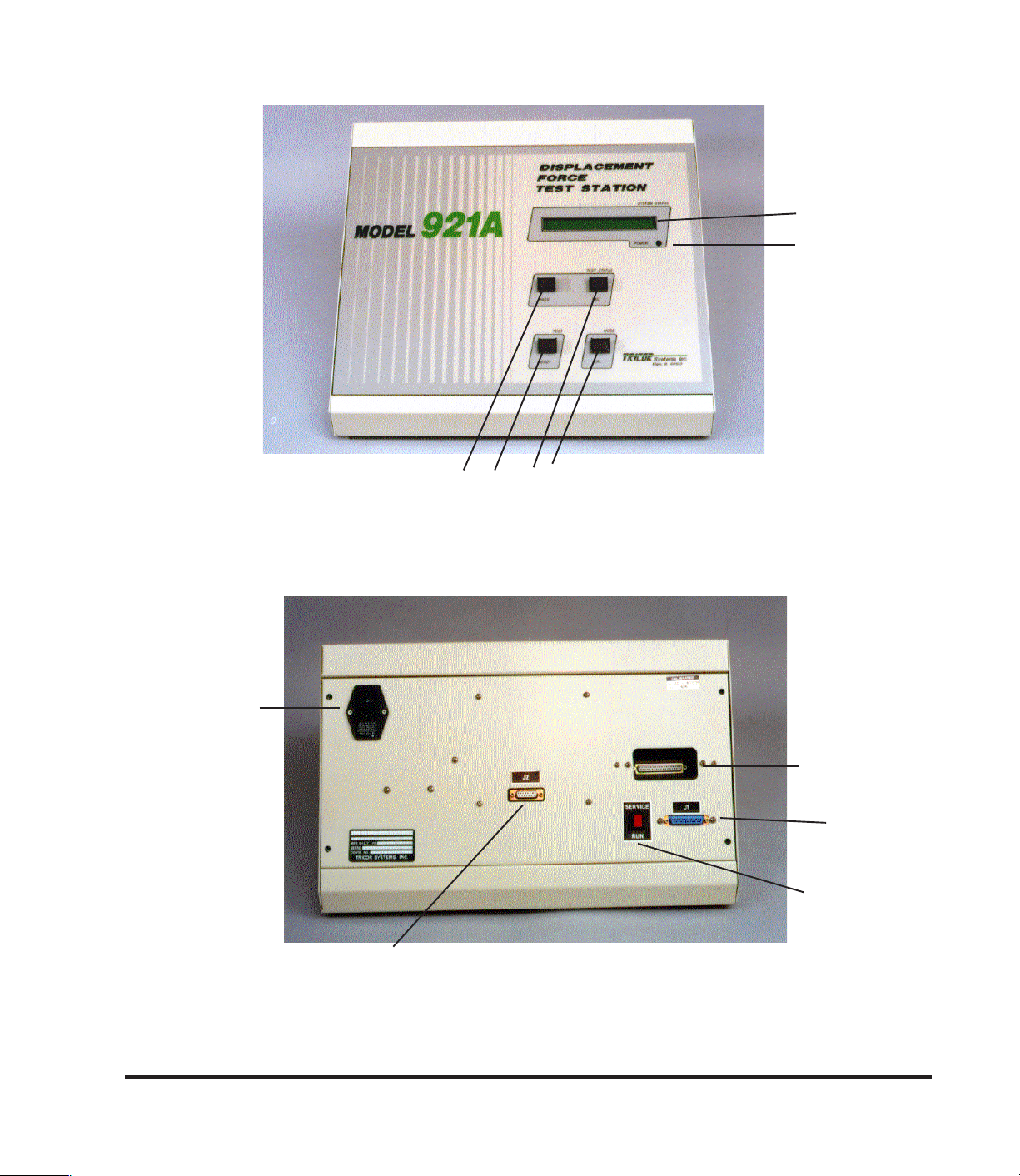
Figure 1.1 921A Controls and Indicators
D
A
B
2-204-4
1.4
Page 6
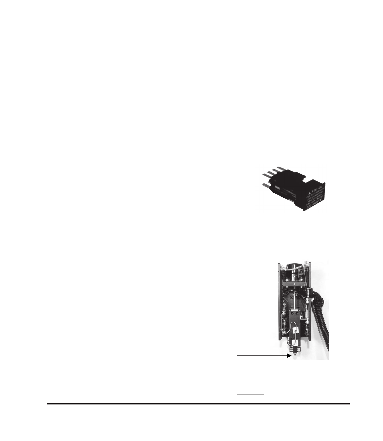
TABLE 1-2
CONTROLS AND INDICATORS
(Refer to Figure 1.1)
A - Back Panel Connector J1 — the serial communication channel
connector used to connect the 921A to a PC using the supplied serial
cable (Figure 1.4 or 1.5).
B - SERVICE/RUN Select Switch — active only when power is first
applied to the 921A. This switch is placed in the RUN position for
normal operation. When the switch is placed in the SERVICE
position, the 921A is in the Service Mode where internal
instrumentation circuits can be adjusted
and various system functions checked.
C - Power Switch / Back Panel Input Power
Module
—
consists of the following:
1) Input power voltage selection permits selecting 110-120 V ac or
220-240 V ac operation by positioning
the slideout voltage selector as
Slideout Panel
indicated in section 2.1.
2) The slideout voltage selector panel contains two fuses. Remove
the slideout panel to access the fuses.
3) Contains the male connector for the power
cord.
4) Contains the power On/Off switch.
D - Precision Drive Mechanism — includes the
motor, lead screw, and precision guide and sensor
used to apply the force to the device under test.
The connector on the corrugated cable of this
assembly is connected to the rear (D) of the 921A
electronics unit.
Precision Drive Mechanism
(Cover Removed)
Force Sensor
1.5
Page 7

TABLE 1-2
CONTROLS AND INDICATORS (Cont.)
E - Back Panel Resistance Connector J2 (optional) — the electrical
resistance connector used with the resistance cable PN 921-112 to
connect 921A to generic or user nests.
F - TEST STATUS PASS Indicator — illuminates green after a test
cycle in which the device being tested passes all of the specified
parameters (within tolerance).
G - TEST Switch / READY Indicator — has two functions:
1) The READY indicator illuminates when the 921A is ready for
another device test sequence. The indicator extinguishes when a
test sequence is initiated or if the 921A is not ready to accept a
device for test.
2) The TEST switch is a pushbutton switch which, when illuminated,
is pressed to initiate a test sequence. This switch is also used to
initiate a calibration cycle when the 921A is in Calibration Mode.
NOTE: The READY indicator does not indicate when to press the TEST
switch. Its function is only to indicate that the 921A is ready for
another test cycle.
H - TEST STATUS FAIL Indicator — illuminates red after a test
sequence in which a device fails one or more of the specified test
parameters (out of tolerance).
I -MODE Switch / CAL Indicator — has two functions:
1) The MODE switch is used to initiate a calibration cycle.
2) The CAL indicator illuminates green when the 921A is in the
Calibration Mode.
1.6
Page 8

TABLE 1-6
CONTROLS AND INDICATORS (Cont.)
J - POWER Indicator — illuminates green when the 921A is turned on
with power applied.
K - SYSTEM STATUS Operator's Display — contains two 40-
character lines which supply information about 921A operation, such
as the part number and version of the device configuration being
tested. This display also prompts the operator concerning necessary
actions, such as "Install Device and Press Ready," etc.
1.7
Page 9
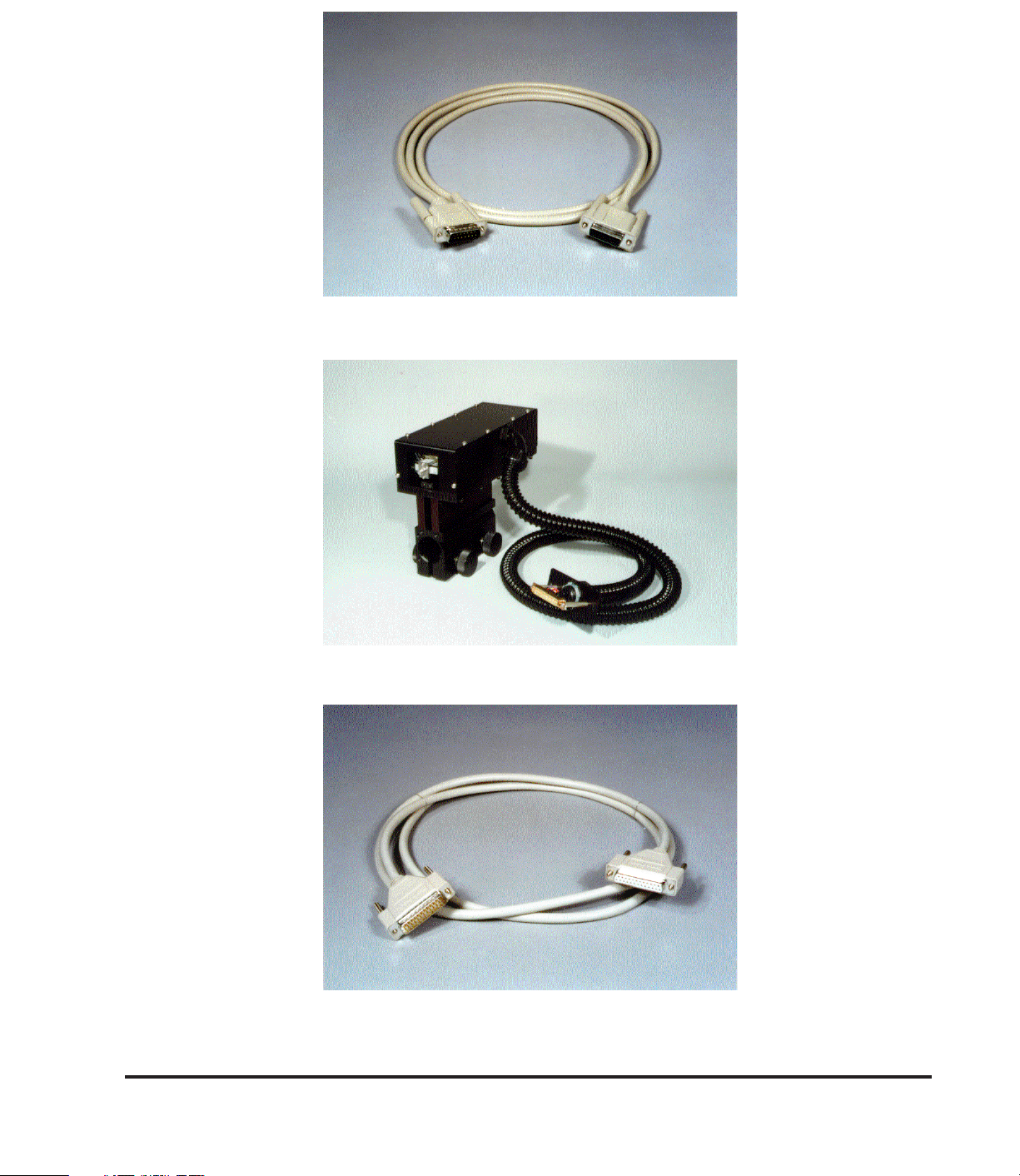
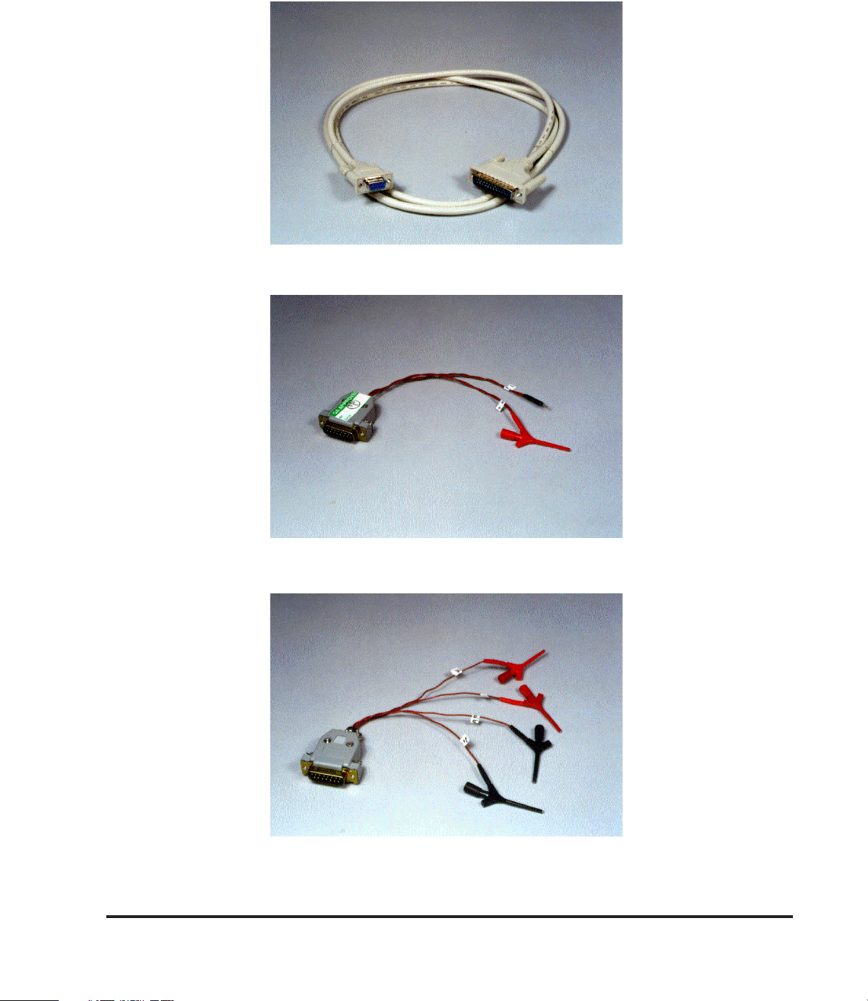
Figure 1.2 Resistance Cable 15-Pin M/F Sub D (Optional)
2-204-5
PN 921-112
2-204-8
Figure 1.3 Precision Drive Mechanism Showing Corrugated Cable
and 37-Pin Connector
2-204-7
Figure 1.4 25-Pin M/F Sub D Serial Cable
PN 905-390-101
1.8
Page 10
2-204-6
Figure 1.5 25 Pin M/ 9-Pin Female Serial Cable
PN 905-390-102
2-204-9
Figure 1.6 Two-Clip Generic Nest Assy
PN 921-140-101
2-204-10
Figure 1.7 Four-Clip Generic Nest Assy
PN 921-140-102
1.9
Page 11

SECTION 2
SETUP AND INTERCONNECTION
2.1 HARDWARE
The power entry module (C-Figure 1.1)
must be set for the user's facility power.
The 921A is normally supplied configured
for 110-120 V ac, 60 Hz. To reconfigure
the 921A for 220-240 V ac, 50-60 Hz
rotate the slideout voltage selector and
position it accordingly. Plug the power
cord into the 921A power entry module
and into a properly grounded outlet.
2.2 PC CONNECTION
The 921A must be connected to a PC to upload configuration data to the
station or download test data to the PC. Connect a PC with an open
communication channel to the 921A using the serial communication cable
supplied with the unit (see Figure 1.4 or 1.5) between the PC Serial COM port
connector and 921A connector J1 (A-Figure 1.1). Tighten the connector
securing screws to ensure a secure connection. If the cable supplied with the
921A is not long enough, a generic 1:1 25-pin
D-type extension cable can be used with the
cable supplied.
110-120V 220-240V
2.3 SOFTWARE
Refer to DFR Operations Software Manual.
Typical Test Fixture
Setup
2.1
Page 12
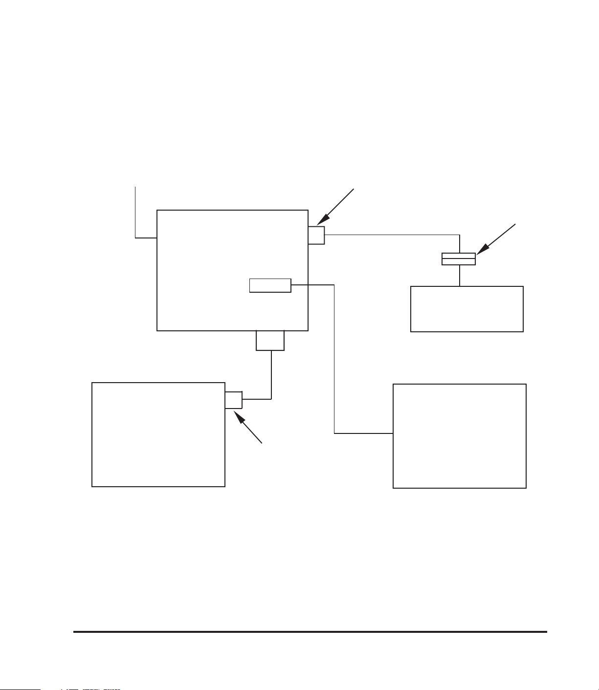
Set up unit for facility power (115 or 220 Vac) prior
to connecting to facility power (see paragraph 2.1).
110 - 120 VAC OR
220 - 240 VAC
WARNING
15-PIN MALE
DF TEST STATION
25-PIN MALE
SERIAL COM
CHANNEL
PC
MODEL 921A
SERIAL CABLE
25-PIN FEMALE
(9-PIN OPTIONAL)
J1
J2
RESISTANCE CABLE
15-PIN FEMALE
GENERIC NEST
PN 921-140-
(OR USER NEST)
PRECISION DRIVE
MECHANISM
Figure 2.1 921A DF Test Station Interconnect
2.2
Page 13
2.4 PRECISION DRIVE MECHANISM SETUP/CONNECTION
A suitable test fixture or vice should be used to hold the device for test. The
drive mechanism force sensor must be centered over the device button,
dome, etc., to which force is to be applied. The sensor must not be in contact
with the device for test (allow at least a 1/16-inch gap). If the optional
platform was purchased, the height of the force sensor above the device for
test can be easily adjusted by loosening the knobs and raising and lowering
the Precision Drive Mechanism to the desired position, and tightening the
knobs.
WARNING
Support the Precision Drive Mechanism when loosening
the knobs or the mechanism will slip on the post,
possibly damaging the force transducer and/or the
device under test.
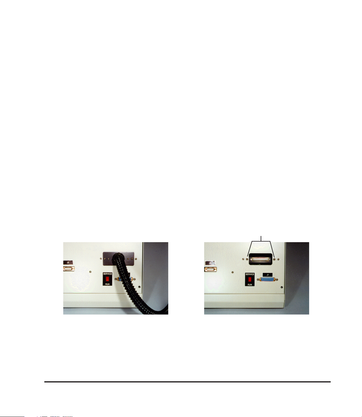
The Precision Drive Mechanism cable connector connects to the rear of the
921A electronic unit using the two screws provided. Refer to Figure 2.2.
Carefully remove the two screws, at the sides of the opening in the rear
panel. Carefully mate the cable connector with the connector recessed in the
rear panel opening. Secure with the two screws removed above.
2 Screws
2-204-12 2-204-11
Figure 2.2a Figure 2.2b
2.3
Page 14

2.5 ELECTRICAL RESISTANCE CONNECTION (OPTIONAL)
The 5-foot 15-pin Subminiature "D" Male/Female connector cable supplied
with the resistance option is used to connect either the supplied generic nest
assembly or the user's nest to the 921A (refer to Figure 1.2).
2.6 GENERIC NEST ASSEMBLY CONNECTION (OPTIONAL)
Two types of Generic Nest Assemblies are available: a two-clip version and a
four-clip version. The type must be specified when ordering.
PN 921-140-101 Two-Clip Version
Resistance channel source and sense plus (red clip) are connected
together and channel source and sense minus (black clip) are connected together. This nest does not allow 4-wire resistance measurement.
PN 921-140-102 Four-Clip Version
Resistance channel source (I+) and sense (S+) plus are separated and
supplied with red clips. Resistance channel source (I-) and sense (S-)
minus are separated and supplied with black clips. This nest allows
performing 4-wire (Kelvin) resistance measurements with the 4 5
resistance options.
2.7 USER NESTS
Table 2-1 shows the wiring of the 15-pin connector J2 on the rear of the unit.
This information is provided for users who wish to wire their own nests.
2.8 FORCE TRANSDUCER TIPS
2.8.1 Interchangeable Force Transducer Tips (2.0 kg, 3.6 kg and 50 lb
Transducers)
2.4
Page 15

Table 2-1
J2 Connector Wiring
PIN SIGNAL
1 INSTALL
2 CH1 SENSE +
3 CH1 SENSE 4
5
6
7
8 CH1 SRC+
9 CHASSIS GROUND
10
11
12
13
14 SIGNAL GND
15 CH1 SRC -
Notes: 1. Pin 9, chassis ground is provided for shield termination. If user-
designed nests have wire lengths in excess of 8 inches, those
wires should be shielded. If the user nest is to be used in an
electrically noisy environment, the wiring should be metal en-
closed with the metal enclosure chassis grounded.
2. Pin 1, INSTALL signal provides a device installed interlock for
testing. The test cycle will not initiate unless the Install signal is
grounded (connected to Pin 14). The user-designed nest can
incorporate a switch which is actuated when a device is in-
stalled in the nest, thereby grounding the Install signal. The
user's nest design can defeat the interlock by jumpering Pin 1 to
Pin 14 if the interlock function is not required.
3. Pin 3, CH1 SENSE - applies only to the 4 5resistance options.
2.5
Page 16
WARNING
Care must be taken whenever handling the force
transducer. These transducers are easily damaged. The 2.0 kg, 3.6 kg and 50 lb transducers
are supplied with protective stops for overload
under compression. However, tension or rotational forces applied in excess of 150% of fullscale rating will permanently damage the transducer.
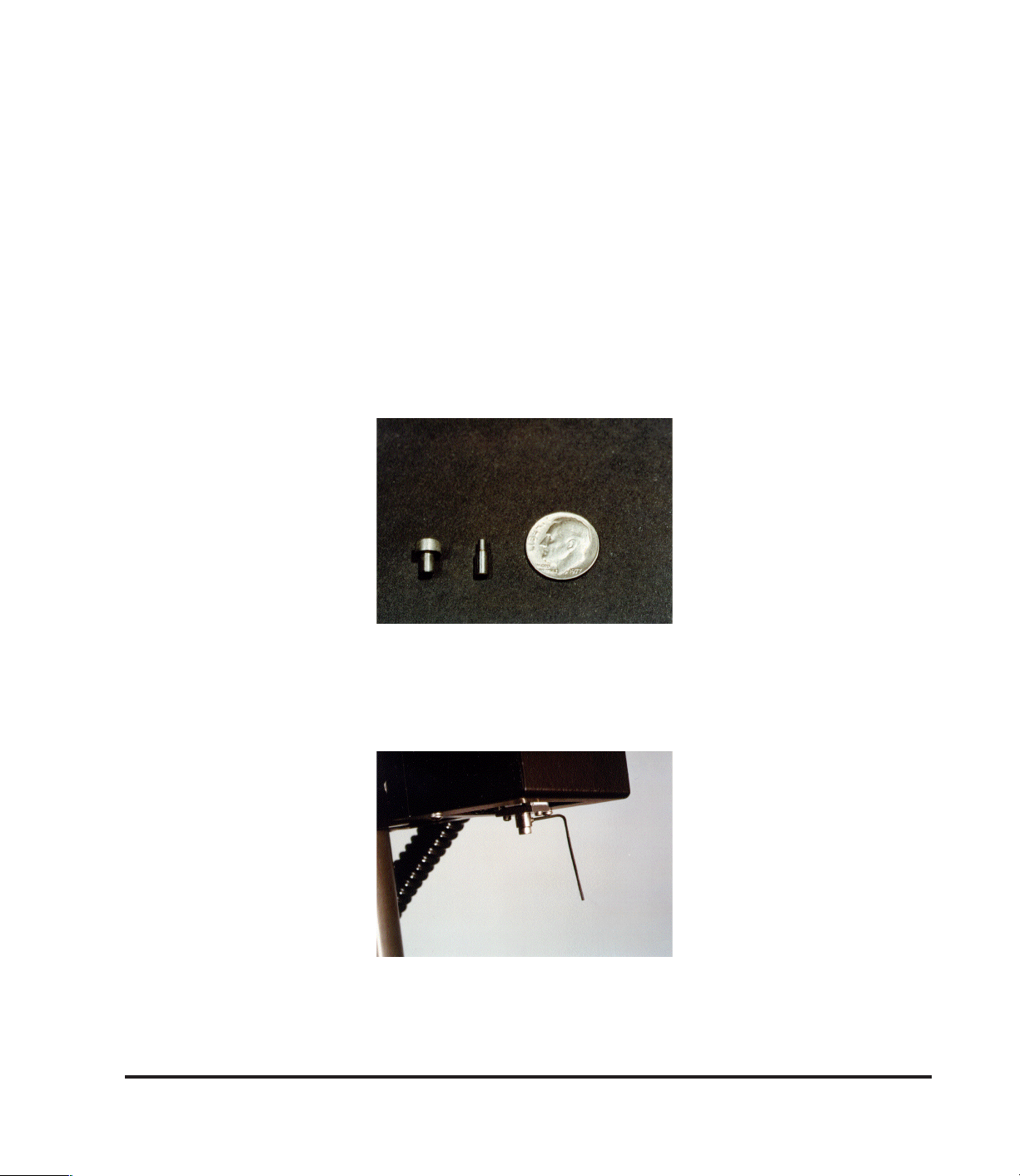
The 2.0 kg, 3.6 kg and 50 lb force transducers are supplied with two tips
(small and large, refer to Figure 2.3). To change tips on the force transducer,
use the allen wrench provided and carefully loosen the set screw holding the
tip (refer to Figure 2.4).
2-204-13
Figure 2.3 Typical Tips
Install the desired tip until it seats (bottoms out) in the transducer opening,
and carefully tighten the set screw with the allen wrench.
2-204-14
Figure 2.4 3.6 kg / 2.0 kg / 50 lb Tip Setscrew Location
2.6
Page 17

CAUTION
If users design their own tips, the mass and length
must be kept at a minimum (comparable to the
large tip supplied) or performance may be impaired.
2.8.2
The 75 g, 360 g and 750 g transducers are supplied with a 4-40 setscrew as
the transducer tip. This setscrew should not be removed. If the user requires
a different size tip, the user tip should be designed to thread onto the 4-40
setscrew.
75 g, 360 g and 750 g Transducer Tips
WARNING
Care must be taken whenever handling the force
transducer. These transducers are easily damaged. Compression, tension or rotational forces
applied in excess of 150% of full scale rating will
permanently damage the transducer.
CAUTION
If users design their own tips, the mass and length
must be kept at a minimum, since performance of
the system may be impaired by the additional
mass/length.
2.9 CHANGING FORCE TRANSDUCER ASSEMBLIES
The 921A allows changing force transducer assemblies (i.e., 3.6 kg, 2.0 kg,
400 g, 75 g, etc.). However each force transducer assembly must be specifically calibrated on the 921A unit on which it is used. Transducer assemblies
calibrated on the same unit can be interchanged without recalibration. Refer
to section 5.1 for transducer calibration information.
2.7
Page 18

WARNING
DO NOT TOUCH THE TRANSDUCER TIP DURING HANDLING OR INSTALLATION/REMOVAL
OR PERMANENT DAMAGE MAY RESULT.
Use proper ESD Handling procedures during
installation/removal and handling/packaging (antistatic) the force transducer assembly. Failure to
comply may result in damage to the equipment.
The transducer assembly consists of the force transducer, the force transducer circuit card assembly (CCA) and the CCA/transducer interconnect
cable.
To remove the transducer assembly from the precision drive mechanism,
remove the cover from this assembly as described in Appendix B, step 1.
Remove the five (5) screws holding the left side plate to the back plate of the
precision drive mechanism (Figure 2.5). Loosen the two (2) screws securing
the harness connector to the force transducer CCA, then disconnect this
connector (Figure 2.6). Remove the four (4) screws securing the force transducer CCA to the side plate (Figure 2.6). Carefully cut the tie wraps securing
the force transducer assembly interconnect cable to the platform tie downs
(Figure 2.7). Support the force transducer and remove the two (2) mounting
screws (Figure 2.8). Carefully remove the transducer assembly. Bubble
wrap and protect the force transducer/tip. Place the transducer assembly in
an antistatic bag for ESD protection.
Install the new transducer on the precision drive mechanism in the reverse
order of removal above. Be sure to secure the transducer interconnect cable
to the tie downs, with tie wraps, as shown in Figure 2.7. The critical tie down
area is the first tie down nearest the transducer. The cable must be secured
to this tie down using two (2) tie wraps, 90o to each other, and tightened
securely. The cable should not be able to be slide through this tie down if
pulled with moderate force. The cable from the transducer to this tie down
also cannot drag or come in contact with any surface during platform movement, or the system will not operate properly.
2.8
Page 19

The remaining two tie down areas are not critical for performance. The cable
should be tied down to these as shown in Figure 2.9 to provide the service
loop for operation. Be sure sufficient slack in the cable is provided so that the
precision drive mechanism limit switch (the furthest extended outward position) is actuated with some slack remaining. When the platform is in the
home position (furthest retracted inward position) there must also be some
slack remaining in the cable.
2.9
Page 20

Screws (5)
2-204-15
Figure 2.5 Figure 2.6
Screws (2)
2-204-18
Figure 2.7 Figure 2.8
Tie downs
Screws (4)
2-204-16
2-204-19
Screws (2)
Tie downs
2-204-17
Figure 2.9
2.10
Page 21

SECTION 3
CONFIGURATION
WARNING
Set up unit for facility power (115 or 220 Vac) prior
to connecting to facility power.
After the 921A has been set up as described in section 2, it is ready for
power.
3.1 TURN-ON
The power ON-OFF switch is located on the back panel as part of the power
module (C-Figure 1.1). Place this switch in the ON position. The green
POWER indicator should illuminate and all other indicators should remain off.
If the POWER indicator does not illuminate, see section 6 Troubleshooting.
3.2 SELF-TEST
Upon application of power, the 921A performs a series of self-tests to verify
that it is functioning properly. If any of the self-tests fail, see section 6
Troubleshooting. The message PERFORMING SYSTEM SELF TEST
TESTING CHECKSUM will appear on the operator's display.
Areas tested during self-test include: CHECKSUM, CPU RAM, RAM 1, RAM
2, and RAM 3. The name of each of these areas is displayed as it is tested.
During the self-test routine, either a message is briefly displayed stating that
an area has passed, or the self-test routine stops and a message is displayed
stating what area has failed. If a failure occurs, the 921A will not allow further
operation. The reason for failure must be corrected before continuing (See
Appendix A).
After a successful self-test, the CAL indicator will illuminate indicating that the
station has automatically entered the Calibration mode. When the 921A is
turned on, it has no reference for measurement and must perform a
calibration cycle as discussed in paragraph 4.1 to establish measurement
references.
If the display indicates a mismatch, the system setup and device are not
compatible with the stored configuration. (See Appendix A)
3.1
Page 22

SECTION 4
OPERATION
After the 921A has been configured, it is ready for operation. Turn on the
921A and allow it to perform its self-test routine and enter the Calibration
Mode.
The operator's display contains two lines of information. The first line
provides data about the device test configuration, i.e., the device part
number, the version of the device configuration, and the work order (if
applicable). This information is dependent upon the device test parameters
stored in memory for the configuration. The second line of the display
provides instructions for the operator.
Note: A valid configuration must be previously installed using the PC DFR
Operations Software. If not, refer to the DFR Operations Software
Manual and create/install a configuration in the 921A prior to
proceeding.
4.1 CALIBRATION MODE
The Calibration Mode is used to obtain measurement references and is
automatically entered upon the successful completion of a self-test routine. It
can also be entered by pressing the MODE switch on the front panel
whenever the operator's display indicates READY. The 921A will also enter
the Calibration Mode if the Configuration is changed and the new device
configuration requires a different calibration. Whenever the 921A is in
Calibration Mode, only the CAL indicator is illuminated.
Press the Mode (CAL) switch to enter the Calibration Mode.
If the configuration parameters include a Reference Block Size (Ref Blk Size)
value other than zero (refer to the DFR Operations Software Manual for
details) the display will prompt for installation of the Distance Reference
Gauge at this point; then to press test. (See restrictions, Appendix A).
If the Ref Blk Size value is zero or not applicable in the configuration, then
the message Ensure Pedestal Setup for CAL is displayed. Press TEST
when ready.
4.1
Page 23

If the configuration uses resistance, then the Generic Nest Assembly (or
equivalent) must be connected to the DF for calibration. If the four-clip
version, PN 921-140-102 is used, the Red clips (I+ and S+) must be
connected together and the black clips (I - and S -) must be connected
together for the purpose of calibration. The red and black clips cannot be
shorting together or to a metal surface. Failure to properly setup the Generic
Nest (or equivalent) will result in a calibration failure message when
calibration is attempted. The calibration process corrects out all system
offsets and hardware deviations so that the device to be tested is the only
unknown.
Install the block or tighten the vice clamp together. Position the sensor
approximately 1/2-inch above the block or vice clamp and press READY.
The message CALIBRATION IN PROCESS will be displayed.
The sensor will move in to the block or vice clamp and back out twice. This
process provides the exact positioning, force, and resistance data required to
accurately test a device.
When the calibration cycle is complete, the READY indicator will illuminate,
the CAL indicator will extinguish, and the message INSTALL DEVICE, THEN
PRESS READY will be displayed. This message indicates that the
calibration cycle is complete. All references have been obtained, and the
921A is ready to test the selected device.
The calibration cycle can be run whenever desired by pressing the MODE
switch. This is useful if the operator suspects the original calibration has
changed. For example, if the sensor has been moved by more than 1 inch,
the original calibration will be invalid and a new calibration cycle will be
necessary to reestablish calibration.
After the MODE switch has been pressed, the message INSTALL
DISTANCE REFERENCE GAUGE (or ENSURE PEDESTAL SETUP for
CAL), PRESS READY WHEN INSTALLED. PRESS CAL TO ABORT will be
displayed.
4.2
Page 24

This message indicates that a calibration cycle has been initiated. If an
operator accidentally pressed the MODE switch, he/she now has the option to
abort the calibration cycle by pressing the CAL switch. The 921A will retain
the former calibration values and be prepared to test another device.
Whenever a different Configuration is installed, the display may instruct the
operator to recalibrate. The 921A will automatically prompt the operator if a
calibration is required due to a configuration change.
4.3
Page 25

SECTION 5
SERVICE & ADJUSTMENTS
5.1 SERVICE MODE
WARNING
The Service Mode operates the moving platform at
some service mode steps. Never operate the unit
without the platform properly setup with the drive
mechanism height adjusted to provide a suitable
stop for the platform force transducer.
The Service Mode provides a means to periodically test and adjust the 921A
internal measurement circuits. Adjustments should be performed on a
regular basis as determined by the user's requirements. The Service Mode
adjustments/calibration should be performed at least on an annual basis.
The SERVICE/RUN switch is located on the back panel (B-Figure 1.1). Turn
off the 921A and place the switch in the SERVICE position. Install a
Calibration Force Gauge under pressure transducer before turning on the
921A. Ensure that the serial communication cable is disconnected from the
921A. Turn on the 921A. It will perform its self-test routine and enter the
Service Mode automatically. The message FORCE CALIBRATION MODE,
PRESS READY TO CONTINUE will be displayed.
The Service Mode requires pressing the TEST/READY switch on the front
panel to increment or step through the various service mode display screens.
The TEST/READY switch must be depressed and held for at least 1 second
prior to release to ensure the unit will recognize that the switch is pressed.
5.1.1 Force Calibration
This step allows adjusting the force offset and gain electronics on the force
transducer assembly. Appendix B provides the detailed instructions for
adjustment/calibration of the force transducer assembly.
If the operator wants to proceed to a different service mode step, be sure the
platform is properly setup (see warning above) then press TEST/READY, as
required.
5.1
Page 26

5.1.2 Resistance Offset (Resistance Option Only)
This step allows adjusting the resistance offset electronics and verifying the
internal resistance gain calibration value, as well as, verifying the resistance
readings.
Appendix C provides the detailed instructions for adjustment/verification of
the resistance electronics.
If the operator wants to proceed to a different service mode step, press
TEST/READY, as required.
5.1.3 Lamp Test
This step allows verifying that the PASS, FAIL, READY, and CAL indicators
are operational. Pressing the CAL switch will alternately turn all these
indicators on and off.
If the operator wants to proceed to the next service mode step, press TEST/
READY, as required.
5.1.4 Resistance CCA Code/Switch Installed (Resistance Option Only)
This step displays the Resistance CCA code (RCCA) value and the switch
installed status. The RCCA code indentifies the specific optional Resistance
CCA type installed in the unit. If the Generic Nest Assembly is connected to
the unit, the SW Install Status should indicate TRUE; if it is disconnected, it
should indicate FALSE.
If the operator wants to proceed to the next service mode step, press TEST/
READY, as required.
5.1.5 Pressure Code
This step displays the Pressure (Force) Transducer Code value. The
Pressure Code identifies the specific transducer type installed on the unit.
5.2
Page 27

If the operator wants to proceed to the next service mode step, press TEST/
READY, as required.
5.1.6 Displacement Verification
This step allows verifying the system displacement accuracy.
Appendix D provides the detailed instructions for verification of the system
displacement.
If the operator wants to proceed to the next service mode step, be sure the
platform is properly setup (see warning above), then press TEST/READY, as
required. In this case the next step is again Force Calibration (para. 5.1.1).
The sequence can be repeated as often as desired.
5.3
Page 28

SECTION 6
TROUBLESHOOTING
User troubleshooting of the 921A is limited to replacing fuses. Before
returning the unit to TRICOR for service, check the following:
1) Verify that the power outlet has power. Plug in and turn on the
921A.
2) Does the POWER indicator illuminate?
Yes - Go to step 3.
No - Remove power plug from outlet.
Remove slideout panel from power entry module (C-Figure 1.1).
Check the two 2-A fuses. Replace defective fuse(s). Reapply
power. If fuse(s) blow, return unit to TRICOR for service.
Otherwise allow 921A to perform its self-test routine.
3) Does the operator's display indicate Self-Test?
Yes - Go to step 4.
No - Return unit to TRICOR for service.
4) Does Self-Test pass?
Yes - Go to step 5.
No - Return unit to TRICOR for service.
5) Does Calibration mode cycle complete?
No - Remove plug from power outlet.
Note:
If the unit is under warranty, contact TRICOR prior to
proceeding.
6.1
Page 29

4-A
Fuse
Remove the back panel (Refer to Appendix C Warnings and
Step 1) prior to removing panel. Check the 4-A fuse (see
Figure 5.1) on the power supply CCA (located on the right side
of the base beneath the operator's display) .
Replace defective fuse, if any, with proper type. Reapply
power. If fuse blows or unit still does not operate properly,
return it to TRICOR for service.
2-204-20
Figure 5.1 4A Fuse Location on Power Supply CCA
6.2
Page 30

APPENDIX A
RESTRICTIONS AND WARNING / PROBLEM / FAILURE
MESSAGE DESCRIPTIONS
Max Force Restriction
Max Force parameter will establish the end of inward travel (bottomout). Max
Force should be set to a reasonable value for the device under test. If the
Max Force is set to small, the inward test range may not reach the desired
bottomout point of the device under test. If the Max Force is set to large
excessive force may be applied to the device under test.
Test Range Travel Restriction
The system can store a maximum of 2,500 data (log) points inward and 2,500
data (log) points outward. With the .0001" lead screw this is approximately
.25" of travel in and out when operating in the 1 step/log mode. Note that this
travel is the test range travel (free position to bottomout) and not total
platform travel. If the test travel range exceeds the 2,500 data (log) points
(more than approx. .25") then invalid results will occur. The configuration
must be changed to increase the steps/log (i.e. 2 steps/log provides ~ .5" test
travel with the standard .0001" lead screw). The user must configure the
parameters properly for the device under test to ensure the test travel does
not exceed the logging capacity of the system, or the test results/data will be
invalid.
Ref Blk Size Restriction
Two restrictions apply to the Distance Reference Gauge and Ref Blk Size.
One is the combination of the platform travel and the Ref Blk size cannot
exceed 6.5535 inches. The other is the location or reference point
established during the calibration cycle using the Distance Reference Gauge
and Ref Blk Size must occur further inward than device bottomout during
device testing. In other words, the reference point must be further (more
travel) away from the platform home position than the device bottomout point
during testing. Failure to comply with these restrictions will cause invalid
results.
A.1
Page 31

Sheet 1 of 2
Nest, press and hold "TEST" to back up platform from Nest. If Force Transducer is not in contact with Nest, check
number of the Force Transducer currently installed.
request and receive the stored results and clear the test result buffer before testing can resume.
Either a device is not proper ly installed, or the Nest is improperly installed or defectiv e.
down unit several minutes, try again. If problem recurs - consult factory.
If problem recurs -- consult factory.
The 921A Force Transducer offset exceeds acceptable limits for testing. Refer to 921A User's Manual for
calibration requirements/procedures for Force Offset. If Force Offset cannot be adjusted to specification -- consult
factory.
Force Gain/Offset calibration. If problem persists -- consult factory.
WARNING / PROBLEM / FAILURE MESSAGE DESCRIPTION
DISPLAY MESSAGE DESCRIPTION
FORCE SENSOR/S ELECTION MISMATCH!!! The current configuration requires a Force Transducer on the 921A with a different part number than the part
TEST BUFFER FULL! WAITING FOR PC The 921A is operating in "PC" mode and the test buffer is full with 32 device test results stored. The PC must
WARNING! LOW BATTERY FOR MEMORY BACKUP. The 921A battery, used to retain configuration data in memory on power down, requires replacement.
THERE IS NO DEVICE INSTALLED TO TEST The 921A does not detect a device present in the Nest when the "TEST" switch is pressed to initia te a tes t cy cle.
A/D RESET, CALIBRATION FAILURE The 921A Analog-to-Digital Converter has failed to reset and calibrate properly. This is a hardware failure. Power
A/D CAL, CALIBRATION FAILURE The 921A Analog-to-Digital converter has failed to calibrate properly. Power down unit several minutes, try again.
A/D CONVERSION (EOC) FAILURE The 921A Analog-to-Digital Converter is not operating properly -- consult factory .
(Press Test to T ry Aga in . )
FORCE OFFSET CAL FAILURE
WARNING!!! FORCE LIMIT EXCEEDED. The Force measured by the Force Transducer exceeds the acceptable limit. If Force Transducer is in contact with
A.2
Page 32

Sheet 2 of 2
Resistance channel offset calibration failure. Check Nest, using correct calibration block or Generic Nest, to
ensure that Nest is pr operly installed. Be sure calibration block is properly seated and making contact with nest
socket. Be sure configuration resistance channel allocation is correct for Nest design. Check resistance channel
calibration and adjust if necessary. If problem persists -- consult factory.
Resistance channel gain calibration failure. Check Nest, using correct calibration block or Generic Nest, to ensure
that Nest is properly installed. Be sure calibration block is properly seated and making contact with Nest socket.
Be sure configuration resistance channel allocation is correct for Nest design. Check resis t ance channel
calibration and adjust if necessary. If problem persists -- consult factory.
Force limit exceeded or Limit switch contacted during platform travel. Typical cause is Maximum Force parameter
in configuration file set too high (near limit of transducer). Reduce Maximum Force parameter value. Other
causes are hardware failures -- consult factory.
and PC or PC being turned off during communication. If necessary, power down 921A and retry operating unit. If
problem persists -- consult factory.
The stored configuration does not contain a valid configuration. Refer to 921A User's Manual and install a
configuration.
If the 921A is operating in Engineering Mode, the test cycle is normally initiated by the remote PC and this
message is displayed if the 921A Test switch is pressed. If the 921A is operati ng in PC Mode, this message can
problem persists -- consult factory.
be displayed if the test switch is pressed while a PC serial data transfer is in process. This occurs infrequently and
WARNING / PROBLEM / FAILURE MESSAGE DESCRIPTION
No Nest/Cable
DISPLAY MESSAGE DESCRIPTION
SWITCH OFF SET CAL FAILURE.
Power Down or Press Test to Retry CAL.
SWITCH GAIN C AL FAILURE.
TESTING ABORTED - POWER DOWN.
Power Down or Press Test to Retry CAL.
FORCE OR LIMIT SWT SYSTEM FAILURE
WAITING -- SERIAL COMMUNICATION RS-232 serial communication with PC interrupted. Possible cause is loose or disconnected cable between 921A
SELF TEST FAILURE - POWER DOWN If self test fails, note failure indicted on second line of 921A display. Power down 921A and retry operation. If
POWER DOWN OR CHANGE SELECTION
NO VALID TEST CONFIGURATION STORED
PLEASE WAIT. . . .
951A HALTED BY EXTERNAL CONTROL!
SYSTEM FAILURE!! FORCE LIMIT EXCEE DED Force limit exceeded. Check force calibration per 921A User's Manual. If problem persists -- consult factory.
A.3
Page 33

APPENDIX B
Force Transducer CCA Calibration
Test Tool Required: Force Calibration Fixture PN 905-810
WARNING
Service is to be performed by qualified
personnel only. Use only plastic adjustment
tools. Failure to comply may result in damage
to the equipment.
Step 1 Power down the unit. Remove the cover from the drive
mechanism assembly (12 screws, Figure B.1). The force
transducer CCA is located on the left side of the drive
mechanism.
Step 2 Assemble the force calibration fixture PN 905-810 by attaching
the force gauge with 2 screws (provided) to the "L" bracket
(Figure B.2) Thread the force gauge tip (Figure B.3) onto the
force gauge. Install the assembled "L" bracket with force gauge
on the 921A baseplate (or equivalent) such that the force gauge
tip is centered under the 921A drive mechanism assembly force
transducer (refer to Figure B.4).
Step 3 Place the SERVICE/RUN switch on the unit rear panel in the
SERVICE position.
The Service Mode is used to perform the calibration/adjustment.
The Service Mode requires pressing the TEST/READY switch on
the front panel to increment or step through the various service
mode display screens. The TEST/READY switch must be
depressed and held for at least 1 second prior to release to
ensure the unit will recognize that the switch is pressed.
Step 4 Turn on the unit. After successful completion of the power-up
self-test, the unit displays the FORCE CALIBRATION MODE
message. Press the TEST/READY switch once. The message
to Adjust Force Pot and the Offset value is displayed. The force
transducer offset adjustment is performed using this display.
B.1
Page 34

Step 5 There are two types of force transducer CCAs which are
illustrated in Figures B.5a and B.5b. Examine your unit's force
transducer CCA to determine which type is on the unit.
Reference figure a or b accordingly to perform the adjustments
of steps 6, 7, and 8.
Step 6 Adjust the force transducer CCA potentiometer labeled "offset"
on Figure B.5 until the offset value displayed on the unit is as
close to the nominal value listed below for your transducer type.
The force offset adjustment must be within the range listed
below for your transducer type for proper calibration.
Type Nominal Acceptable Range
3.6 kg 0.075 kg 0.025 to 0.200 kg
360 g 7.5 g 2.5 to 20.0 g
75 g 1.6 g .5 to 4.2 g
2.0 kg 0.038 kg 0.012 to .100 kg
750 g 15 g 5 to 42 g
50 lb 1.04 lb .35 lb to 2.80 lb
20 lb 0.38 lb 0.12 to 1.00 lb
Step 7 Turn on the force gauge. Select the units (kg or g) and zero the
force gauge. Press the TEST/READY switch once. The unit
drive mechanism will operate until the unit force transducer is in
contact with the force gauge and reaches the calibration force
level. The unit displays the adjust force pot(s) message for
Force = Gauge value and displays
Force = "Measured Value"
Refer to Figure B.5 and adjust the GAIN 1 and/or the GAIN 2
potentiometer until the unit force "Measured Value" is equal to
the force gauge value within the tolerance listed below for your
transducer type.
Adjustment Specification
Type Tolerance Tolerance
3.6 kg ± .003 kg ± .010 kg
360 g ± 0.4 g ± 2.0 g
75 g ± 0.1 g ± 0.5 g
2.0 kg ± .002 kg ± .005 kg
750 g ± 0.8 g ± 3.8 g
50 lb ± 0.04 lb ± 0.25 lb
20 lb ± 0.02 lb ± 0.10 lb
B.2
Page 35

Step 8 Press the TEST/READY switch once. When the platform
mechanism stops moving power down the unit. Repeat steps 4
through 8 until the step 6 offset is within acceptable range and
the step 7 Measured Value is within adjustment tolerance
without requiring further potentiometer adjustment, at steps 6
and 7. It typically takes performing steps 4 through 8 at least
three times to achieve correct adjustment.
Step 9 Apply a small amount of Glytol to the potentiometer adjustment
screw being sure some Glytol is applied between the screw and
the body of the potentiometer. This completes the force
transducer calibration.
Step 10 Install the cover on the head assembly with the screws removed
in step 1. Remove the "L" bracket with force gauge from the
baseplate. Remove the force gauge from the "L" bracket. Store
force gauge and tip in original shipping case for protection.
B.3
Page 36

Screws (12)
2-204-21
Figure B.1 Drive Mechanism Assembly Cover Removal
B.4
Page 37

2-204-22
2-204-24
Figure B.2 L Bracket/Gauge
B.5
Page 38

Figure B.3 Force Gauge with Tip
2-204-23
B.6
Page 39

Figure B.4 Center Gauge to Transducer Tip
2-204-25
B.7
Page 40

GAIN 1GAIN 2
GAIN 1GAIN 2
Figure B.5a Resistance Pot Locations
Force Transducer CCA Type 1
2-201-43
OFFSET
OFFSET
GAIN 2 GAIN 1
OFFSET
Figure B.5b Resistance Pot Locations
Force Transducer CCA Type 2
2-204-26
B.8
Page 41

APPENDIX C
Resistance Adjustment/Verification
(Resistance Option Only)
Test Tool Required: Resistance Verification Fixture PN 921-811-XX
(See Table C-1 for the complete part number of the
fixture required based on the Resistance Option Type
installed in the Model 921A)
Table C-1
Resistance Option Type Resistance Fixture PN
4 5, 10mA 921-811-09
4 5, 25mA 921-811-09
16 k5, .25mA 921-811-01
1 k5, 1 mA 921-811-07
4 V, 4.99k Pullup 921-811-02
Each fixture consists of: The Resistance Test Box, a 37-pin to 15-pin
adapter cable and the Offset/Gain Jumpering
Connector.
Resistance Test Box Offset/Gain
Jumpering Connector
WARNING
DANGER
There is 115 V or 230 V ac voltages present
within the unit. Service is to be performed by
qualified personnel only. Use only plastic
adjustment tools. Do not touch or come in
physical contact with any wires, components or
assemblies within the unit or severe injury or
death can result.
C.1
Page 42

WARNING
The Service Mode operates the moving platform
at some service mode steps. Never operate the
unit without the platform properly set up with the
test fixture height adjusted to provide a suitable
stop for the platform force transducer.
Step 1 Power down the unit. Disconnect the ac power cord from the
primary power source. Remove the rear panel from the unit
(four screws - figure C.1) and lay down on a flat surface.
Step 2 Adjust the height of the Drive Mechanism to provide a suitable
stop for the platform force transducer.
Step 3 Connect the Drive Mechanism and Resistance Cable (PN 921-
112) to the rear panel connectors per section 2 of the 921A
User's Manual; however, do not connect P2 of the resistance
cable to a nest. Connect the ac power cord to the unit and to
the primary power source. Place the SERVICE/RUN switch on
the unit rear panel in the SERVICE position. Turn on the unit.
The Service Mode is used to perform the calibration/adjustment.
The Service Mode requires pressing the TEST/READY switch
on the front panel to increment or step through the various
service mode display screens. The TEST/READY switch must
be depressed and held for at least 1 second prior to release to
ensure the unit will recognize that the switch is pressed.
Step 4 After successful completion of the power-up self-test, the unit
displays the Force Calibration Mode message. The Force
Calibration will not be performed as part of this procedure.
However, the unit must be sequenced through the service mode
Force Calibration screens by pressing the TEST/READY switch
on the front panel.
Press TEST/READY once- Force Offset Value displayed
Press TEST/READY again - Platform moves until Force Cal
value is reached and stops.
C.2
Page 43

Rear Panel
Mounting
Screws (4)
Figure C.1 921A Rear Panel
2-204-4
Press TEST/READY again - The platform returns to the home
position. The resistance Offset
Adjustment Mode message is
displayed.
Install the Offset/Gain Jumpering Connector (part of PN 921811-XX) on the Resistance Cable (PN 921-112) P2 Connector.
Do not remove the jumpering connector until instructed to
do so by this procedure.
Step 5 Press the TEST/READY switch once. The unit displays the
offset values for the resistance current source channel. Figure
C.2 identifies the location of the offset potentiometer (pot) and
the corresponding pot designator which is displayed by the unit.
Step 6 The resistance offset value must be within the acceptable range
listed below. If necessary, adjust the offset pot until the offset
value displayed by the unit is within the acceptable range.
C.3
Page 44

OFFSET POT
R21
Figure C.2 Resistance CCA Offset Pot Location
2-204-27
C.4
Page 45

Resistance Type Acceptable Range
4 5, 10 mA Channel Offset 0.010 to 0.030
4 5, 25 mA Channel Offset 0.004 to 0.012
16 k5, .25 mA Channel Offset 0.001 to 0.030
1 k5, 1 mA Channel Offset 0.001 to 0.030
4 V, 4.99 k Pullup Channel Offset 0.001 to 0.030
Step 7 Press the TEST/READY switch once. The unit displays the
GAIN Calibration Resistance Value message. Press the TEST/
READY switch again. The unit displays the GAIN Calibration
Value (GV). The Gain Values displayed should be in the range
3.800 ± .100. These are not adjustable values. Consult the
factory if the GV value is not within this range.
Step 8 Press the TEST/READY switch once. The unit displays the
Contact Resistance Value Mode message. Press the TEST/
READY switch again. The unit displays the measured
resistance for the resistance channel. The value displayed
must be 4.095. This is the open circuit condition. Consult the
factory if the channel is not equal to this value.
Step 9 Remove the Offset/Gain jumpering connector from the
Resistance Cable P2 connector. Connect the Resistance Test
Box (Part of PN 921-811-XX) connector to the Resistance Cable
P2 Connector.
Tables C.2 through C.5 provide the switch settings and
verification criteria for the different Resistance Option types.
Use the appropriate table for the Resistance Option installed in
the 921A.
Set the Resistance Test Box Resistance switch to each position
listed in the appropriate table below and verify that the value
displayed by the unit (CH1) equals the corresponding value
listed in the table within the tolerance specified.
C.5
Page 46

Table C.2 4 5, 10 mA or 25 mA Resistance Option using Resistance
Fixture PN 921-811-09
Resistance Switch Position Displayed Value (5) Tolerance
1 (0 5) 0.000 ±.010
2 (1 5) 1.000 ±.010
3 (2 5) 2.000 ±.010
4 (3 5) 3.000 ±.010
5 (3.8 5) 3.800 ±.010
6 (.025 5) 0.025 ±.010
7 (.050 5) 0.050 ±.010
8 (.075 5) 0.075 ±.010
Table C.3 16 k5, .25 mA Resistance Option using Resistance Fixture
PN 921-811-01
Resistance Switch Position Displayed Value* Tolerance
0 (0 k5) 0.000 ± 0.010
1 (4 k5) 1.000 ± 0.010
2 (8 k5) 2.000 ± 0.010
3 (12 k5) 3.000 ± 0.010
4 (16 k5) 4.000 ± 0.010
* Resistance = Displayed Value x 4000 (5)
Table C.4 1 k5, 1 mA Resistance Option using Resistance Fixture
PN 921-811-07
Resistance Switch Position Displayed Value* Tolerance
0 (0 5) 0.000 ± 0.010
1 (250 5) 1.000 ± 0.010
2 (500 5) 2.000 ± 0.010
3 (750 5) 3.000 ± 0.010
4 (1000 5) 4.000 ± 0.010
* Resistance = Displayed Value x 250 (5)
C.6
Page 47

Table C.5 4 V, 4.99k Pullup Resistance Option using Resistance
Fixture PN 921-811-02
Resistance Switch Position Displayed Value (Volts) Tolerance
0 (0 V) 0.000 ± 0.040
1 (1 V) 1.000 ± 0.040
2 (2 V) 2.000 ± 0.040
3 (3 V) 3.000 ± 0.040
4 (4 V) 4.000 ± 0.040
Consult the factory if any of the resistance values fail to meet
the specified requirement. This completes the resistance
calibration/verification.
Step 10 Power down the unit. Disconnect the ac power cord from the
primary power source. Disconnect Test Tool PN 921-811-09
from the Resistance Cable P2 connector.
Step 11 If the potentiometer was adjusted, apply a small amount of
Glytol to the potentiometer adjustment screw being sure
some Glytol is applied between the screw and the body of
the potentiometer.
Step 12 If no further internal adjustments are to be made, install the
rear panel on the unit using the four screws removed in
step 1.
C.7
Page 48

APPENDIX D
Displacement Verification Procedure
Test Tool Required: Force/Displacement Gauge Fixture PN 905-378
Displacement Gauge: Mitutoyo PN 543-146 (or Equivalent)
Align Parallel
2-204-28
Figure D.1 Fixture with Gauge
WARNING
The Service Mode operates the moving platform
at some service mode steps. Never operate the
unit without the platform properly setup with the
test fixture height adjusted to provide a suitable
stop for the platform force transducer.
Step 1 Adjust the height of the Drive Mechanism to provide a suitable
stop for the drive mechanism force transducer.
D.1
Page 49

Step 2 Connect the Drive Mechanism to the rear panel connector per
section 2 of the 921A User's Manual. Connect the ac power
cord to the unit and to primary power source. Place the
SERVICE/RUN switch on the unit rear panel in the SERVICE
position. Turn on the unit.
The Service Mode is used to perform the calibration/adjustment.
The Service Mode requires pressing the TEST/READY switch
on the front panel to increment or step through the various
service mode display screens. The TEST/READY switch must
be depressed and held for at least 1 second prior to release to
ensure the unit will recognize that the switch is pressed.
Step 3 After successful completion of the power-up self-test, the unit
displays the Force Calibration Mode message. The Force
Calibration will not be performed as part of this procedure.
However, the unit must be sequenced through the Service Mode
Force Calibration screens by pressing the TEST/READY switch
on the front panel.
Press TEST/READY once - Force Offset Value displayed
Press TEST/READY again - Platform moves until Force Cal
Value is reached and stops.
Press TEST/READY again - The platform returns to the home
position.
If the unit is equipped with the Resistance Option, Resistance
Offset Mode is displayed. If not, the Lamp Test Mode message
is displayed. Press TEST/READY switch, as required, until the
Displacement Verification Mode message is displayed, then
proceed to step 4.
Step 4 Assemble the Displacement Gauge to Fixture PN 905-378, as
shown in Figure D.1, using the bolt provided. Be certain the
gauge is mounted with the plunger parallel to the side of the
fixture (see Figure D.1). Install the assembled fixture with
gauge on the 921A baseplate (optional) or equivalent, such that
the displacement gauge plunger is slightly depressed
D.2
Page 50

(approximately 1/16-inch) when contacting the Force Transducer
Assembly (adjust the height of the drive mechanism, as
necessary) as shown in Figure D.2.
Figure D.2
2-204-29
Step 5 Prior to proceeding with the displacement test, the operator
needs to become familiar with the test method. Table D.1
provides the approximate displacement locations to test. When
the TEST/READY switch is pressed and released, the drive
mechanism will begin incrementing (moving) into the
displacement gauge. The 921A displacement value is presented
on the unit display. The drive mechanism is incremented until
the displacement reaches 0.2000 inch (standard .0001 inch lead
screw) or until the TEST/READY switch is pressed and held in.
The drive mechanism will remain stationary as long as the
TEST/READY switch is held in (actuated). By monitoring the
displacement value on the unit display and pressing/holding the
TEST/READY switch, the operator can stop the platform at the
approximate displacement points listed in Table D.1 and
compare the unit displayed displacement to that of the fixture
gauge.
D.3
Page 51

Step 6 With the Displacement Verification Mode message displayed on
the unit, turn on and zero the fixture gauge. Be sure the fixture
gauge reads zero, or re-zero the gauge as necessary until the
gauge reads zero before proceeding. Press, then release, then
press and hold in the TEST/READY switch. This is the
approximate zero reading. If the unit display still reads zero,
then re-zero the fixture gauge (if necessary). If the unit reads
other than zero, any difference should be noted and subsequent
fixture gauge readings corrected for the initial zero difference.
Release the TEST/READY switch, monitor the unit displacement
until the next approximate displacement point, then press and
hold the TEST/READY switch. Compare the fixture gauge to the
unit displayed value. The unit value must be within ±0.0003
inch of the corrected gauge value for each displacement check
for acceptance. Repeat until all displacement points listed in
Table D-1, prior to the last displacement point, have been
checked. The unit will automatically stop at the last
displacement point (Do not press TEST/READY switch for this
point). Check the unit displacement to the gauge at this point as
well.
Step 7 Press TEST/READY switch again. The drive mechanism will
retract and go to the home position. This completes the
displacement verification.
Step 8 Power down unit. Remove fixture from baseplate. Remove and
store gauge in original shipping case for protection.
D.4
Page 52

Table D-1
Displacement Verification Table
Approximate Unit Measurement Mitutoyo
Displacement Measurement
0.0000
0.0125
0.0250
0.0500
0.0750
0.1000
0.1250
0.1500
0.1750
0.2000
D.5
 Loading...