

Shimano XTR Di2 Dealer's Manual

(English)
DM-XTR001-01
XTR Di2
M9050 series
Dealer's Manual
MTB
XTR
RD-M9050
FD-M9050
FD-M9070
SM-FD905
SW-M9050
SM-BTC1
SC-M9050

2
CONTENTS
IMPORTANT NOTICE .............................................................................................. 4
TO ENSURE SAFETY ............................................................................................... 5
INSTALLATION ..................................................................................................... 15
Electrical wiring diagram ...........................................................................................................................15
List of tools to be used ...............................................................................................................................18
Installing the system information display .................................................................................................19
Installation of junction (A) ........................................................................................................................20
Installation of the shifting switch .............................................................................................................21
Installation of the front derailleur ............................................................................................................22
Installation of the rear derailleur ..............................................................................................................27
Connection of the electric wires ...............................................................................................................29
Installation of the battery .........................................................................................................................32
Connecting the suspension ........................................................................................................................40
Checking connections ................................................................................................................................40
Installation of the chain .............................................................................................................................41
How to operate ................................................................................................... 43
Basic operations of the shifting switch .....................................................................................................43
Gear position control .................................................................................................................................44
Displaying and operating the system information display ......................................................................45
Error message .............................................................................................................................................49
ADJUSTMENT ...................................................................................................... 51
Adjustment of the rear derailleur .............................................................................................................51
Adjustment of the front derailleur ...........................................................................................................56
Adjusting rear derailleur friction ..............................................................................................................68

3
CHARGING THE BATTERY ....................................................................................71
Names of parts ...........................................................................................................................................71
Charging the battery .................................................................................................................................73
Troubleshooting for charging error .......................................................................................................... 75
Connection and communication with the PC ................................................... 77
Settings customizable in E-tube Project ...................................................................................................77
Connecting to a PC .....................................................................................................................................79
MAINTENANCE .................................................................................................... 83
Replacing parts - shifting switch ...............................................................................................................83
Replacing parts - rear derailleur ................................................................................................................84
Replacing rubber pad A .............................................................................................................................89
Replacing rubber pad B .............................................................................................................................92
Disconnection of the electric wires ...........................................................................................................93
4
IMPORTANT NOTICE
IMPORTANT NOTICE
•
This dealer’s manual is intended primarily for use by professional bicycle mechanics.
Users who are not professionally trained for bicycle assembly should not attempt to install the components themselves using the dealer’s manuals.
If any part of the information on the manual is unclear to you, do not proceed with the installation. Instead, contact your place of purchase or a local
bicycle dealer for their assistance.
•
Make sure to read all instruction manuals included with the product.
•
Do not disassemble or modify the product other than as stated in the information contained in this dealer’s manual.
•
All dealer’s manuals and instruction manuals can be viewed on-line on our website (http://si.shimano.com).
•
Please observe the appropriate rules and regulations of the country, state or region in which you conduct your business as a dealer.
For safety, be sure to read this dealer’s manual thoroughly before use, and follow it for correct use.
The following instructions must be observed at all times in order to prevent personal injury and physical damage to equipment and surroundings.
The instructions are classified according to the degree of danger or damage which may occur if the product is used incorrectly.
DANGER
Failure to follow the instructions will result in death or serious injury.
WARNING
Failure to follow the instructions could result in death or serious injury.
CAUTION
Failure to follow the instructions could cause personal injury or physical damage to equipment and surroundings.

5
TO ENSURE SAFETY
TO ENSURE SAFETY
DANGER
Be sure to also inform users of the following:
Lithium ion battery
Be sure to observe the following in order to avoid burns or other injury from fluid leakages, overheating, fire or explosions.
•
Use the designated charger to charge the battery. If any non-specified items are used, fire, overheating or leakages may occur.
•
Do not heat the battery or throw it into fire. If this is not observed, fire or bursting may occur.
•
Do not disassemble or modify the battery or apply solder directly to the battery terminals. Do not leave the battery in places which may exceed 60°C in
temperature, such as places which are exposed to direct sunlight inside vehicles on hot days or near stoves. If this is not observed, leakages,
overheating or bursting may cause fire, burns or other injury to occur.
•
Do not connect the (+) and (-) terminals with metallic objects. Do not carry or store the battery together with metallic objects such as necklaces or
hairpins. If this is not observed, short-circuits, overheating, burns or other injury may occur.
•
If any liquid leaking from the battery gets into the eyes, immediately wash the affected area with clean water without rubbing the eyes, and then
seek medical attention. If this is not done, blindness may occur.
Battery charger / Battery charger cord
Be sure to observe the following in order to avoid burns or other injury from fluid leakages, overheating, fire or explosions.
•
Do not get the charger wet or use it while it is wet, and do not touch or hold it with wet hands. If this is not observed, problems with operation or
electric shocks may occur.
•
Do not cover the charger with a cloth or similar while it is in use. If this is not observed, heat may build up and the case may become deformed, or fire
or overheating may occur.
•
Do not disassemble or modify the charger. If this is not observed, electric shocks or injury may occur.
•
Use the charger at the specified power supply voltage only. If a power supply voltage other than that specified is used, fire, explosions, smoke,
overheating, electric shocks or burns may occur.
•
Do not touch metallic parts of the charger or the AC adapter if there is a lighting storm. When lightning strikes, an electric shock may be caused.
SM-BCR2: Battery charger for SM-BTR2
•
Use an AC adapter with a USB port with a voltage of 5.0 VDC and with a current equal to or higher than 1.0 ADC. If the one with a current lower than
1.0 A is used, the AC adapter may heat up, potentially causing a fire, smoke, overheating, destruction, electric shock, or burns.

6
TO ENSURE SAFETY
WARNING
•
When installing components, be sure to follow the instructions that are given in the instruction manuals.
It is recommended that you use only genuine Shimano parts. If parts such as bolts and nuts become loose or damaged, the bicycle may suddenly fall
over, which may cause serious injury.
In addition, if adjustments are not carried out correctly, problems may occur, and the bicycle may suddenly fall over, which may cause serious injury.
•
Be sure to wear safety glasses or goggles to protect your eyes while performing maintenance tasks such as replacing parts.
•
After reading the dealer's manual thoroughly, keep it in a safe place for later reference.
Be sure to also inform users of the following:
•
Maintenance interval depends on the usage and riding circumstances. Clean the chain regularly with an appropriate chain cleaner. Never use alkali
based or acid based solvents such as rust cleaners. If those solvents are used the chain might break and cause serious injury.
•
When the shifting switch is operated, the powerful motor which drives the front or rear derailleur will operate to the shifting lever position without
stopping, so be careful not to get your fingers caught.
•
Before riding, check that the wheels are secured. Failure to do so may result in serious injury.
•
Check the chain for any damage (deformation or crack), skipping, or other abnormalities such as unintended gear shifting. If any problems are found,
consult a dealer or an agency. The chain may break, and you may fall.
•
Be careful not to let the cuffs of your clothes get caught in the chain while riding, otherwise you may fall off the bicycle.
7
TO ENSURE SAFETY
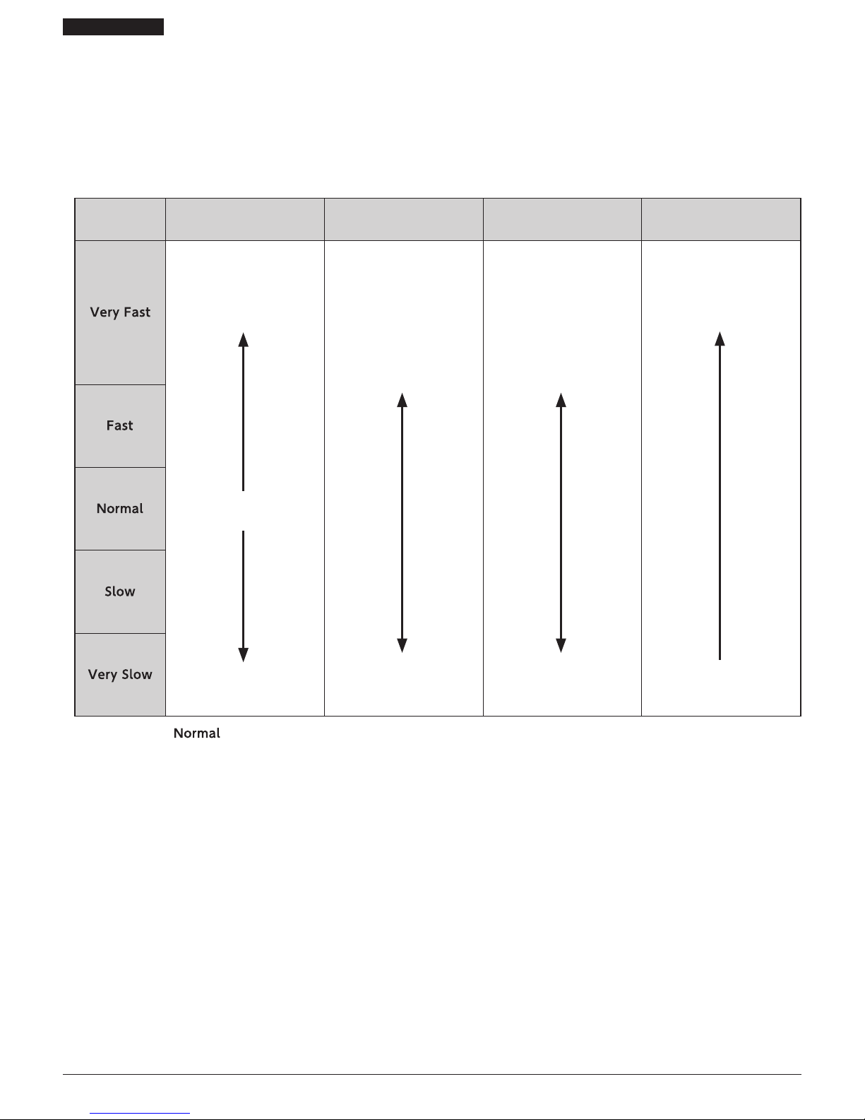
About the multi-shift function
On this system, the multi-shift function can be configured using E-tube Project. The gears will continue to shift when the shifting switch is pressed using
the multi-shift function. Shifting speed setting for multi-shift can also be modified. When modifying the shifting speed settings for multi-shift, carefully
read "Settings customizable in E-tube Project" in this dealer's manual.
If crank revolutions are set to low under faster setting of the multi-shift shifting speed, the chain will be unable to follow the movement of the rear
derailleur, possibly leading to issues such as the chain slipping over the tip of the cassette sprocket teeth, the cassette sprocket deforming, or the chain
breaking.
Item Multi-shift speed Features Usage notes
Crank revolution speed when
operating multi-shift
High speed
Quick multi-shifting is possible
•
The crank rotation speed
can be adjusted quickly
depending on changes in
riding conditions.
•
The speed can be adjusted
quickly.
1. Over-shifting occurs easily.
2. If the rotation speed of the
crank is low, the chain will
be unable to follow the
movement of the rear
derailleur.
The chain may therefore
slip over the tip of the
cassette sprocket teeth.
High crank rotation speed
Default setting
Slow speed
Accurate multi-shifting is
possible
Multi-shifting takes some
time
By default it is set to
.
Fully understand the features of the multi-shift shifting speed, and choose a multi-shift shifting speed setting according to the riding conditions (terrain,
riding method, etc.).

8
TO ENSURE SAFETY
Lithium ion battery
•
Do not place the battery into fresh water or sea water, and do not allow the battery terminals to get wet. If this is not observed, fire, bursting or
overheating may occur.
•
Do not use the battery if it has any noticeable scratching or other external damage. If this is not observed, bursting, overheating or problems with
operation may occur.
•
Do not subject the battery to strong shocks or throw it. If this is not observed, bursting, overheating or problems with operation may occur.
•
Do not use the battery if leakages, discoloration, deformation or any other abnormalities occur. If this is not observed, bursting, overheating or
problems with operation may occur.
•
If any leaked fluid gets on your skin or clothes, wash it off immediately with clean water. The leaked fluid may damage the skin.
•
The operating temperature ranges for the battery are given below. Do not use the battery in temperatures outside these ranges. If the battery is used
or stored in temperatures which are outside these ranges, fire, injury or problems with operation may occur.
1. During discharge: –10 °C - 50 °C
2. During charging: 0 °C - 45 °C
SM-BTR1 : Lithium ion battery
•
If charging is not complete after 1.5 hours of charging, stop charging. If this is not observed, fire, bursting or overheating may occur.
SM-BTR2 : Lithium ion battery
•
If the battery does not become fully charged after 4 hours of charging, stop charging. If this is not observed, fire, bursting or overheating may occur.
Battery charger / Battery charger cord
•
Be sure to hold the power cable by the power plug when connecting and disconnecting the power plug from the electrical outlet. If you do not hold
the power cable by the power plug, fire or electric shocks may occur.
If the following symptoms are observed, stop using the device and contact a dealer. A fire or electric shock may be caused.
*
If heat or acrid-smelling smoke is coming out from the power plug.
*
There may be a bad connection inside the power plug.
•
Do not overload the electrical outlet with appliances beyond its rated capacity, and use only a 100 – 240 V AC electrical outlet. If the electrical outlet is
overloaded by connecting too many appliances using adapters, overheating resulting in fire may occur.
•
Do not damage the power cord or power plug. (Do not damage, process, forcibly bend, twist or pull them, bring them near hot objects, place heavy
objects on them or bundle them tightly together.) If they are used while damaged, fire, electric shocks or short-circuits may occur.
•
Do not use the charger with commercially-available electrical transformers designed for overseas use, as they may damage the charger.
•
Always be sure to insert the power plug as far as it will go. If this is not observed, fire may occur.
SM-BCR2: Battery charger for SM-BTR2
•
Do not use any USB cable other than the USB cable which is supplied with the PC linkage device. This may cause a charge error, fire, or failure of the
connected PC due to heating.
•
Do not connect the charger to PC when it is on standby. This may cause a failure of PC depending on its specifications.
•
When connecting or disconnecting the USB cable or the charging cable, be sure to hold the plug of the cable. Failure to do so may cause a fire or
electric shock.
•
If the following symptoms are observed, stop using the device and contact a dealer. A fire or electric shock may be caused.
*
If heat or acrid-smelling smoke is coming out from the power plug.
*
There may be a bad connection inside the power plug.
•
If it thunders while charging with an AC adapter with a USB port, do not touch the device, bicycle, or the AC adapter. When lightning strikes, an
electric shock may be caused.
•
Use an AC adapter with a USB port with a voltage of 5.0 VDC and with a current equal to or higher than 1.0 ADC. If the one with a current lower than
1.0 ADC is used, a charge error may occur or the AC adapter may heat up, leading to a fire.
•
Do not use a USB hub when connecting the cable to a PC USB port. This may cause a charge error or fire due to heating.
•
Be careful not to damage the charging cable. (Do not damage, process, forcibly bend, twist or pull them, bring them near hot objects, place heavy
objects on them or bundle them tightly together.) If they are used while damaged, fire, electric shocks or short-circuits may occur.

9
TO ENSURE SAFETY
Brake
•
Each bicycle may handle slightly differently depending on the model. Therefore, be sure to learn the proper braking technique (including brake lever
pressure and bicycle control characteristics) and operation of your bicycle. Improper use of your bicycle's brake system may result in a loss of control or
a fall, which could lead to severe injury. For proper operation, consult your professional bicycle dealer or the bicycle's owner's manual. It is also
important to practice riding and your braking technique, etc.
•
If the front brake is applied too strongly, the wheel may lock and the bicycle may fall forward, and serious injury may result.
•
Always make sure that the front and rear brakes are working correctly before riding the bicycle.
•
The required braking distance will be longer during wet weather. Reduce your speed and apply the brakes early and gently.
•
If the road surface is wet, the tires will skid more easily. If the tires skid, you may fall off the bicycle. To avoid this, reduce your speed and apply the
brakes early and gently.
CAUTION
Be sure to also inform users of the following:
Lithium ion battery
•
Store the battery in a safe place away from the reach of infants and pets.
SM-BTR1 : Lithium ion battery
•
When you do not use the battery for a long period, remove and charge the battery before storage.
SM-BTR2 : Lithium ion battery
•
When you do not use the battery for a long period, charge the battery before storage.
Battery charger / Battery charger cord
SM-BCR2: Battery charger for SM-BTR2
•
Disconnect the USB cable or the charging cable when performing maintenance.

10
TO ENSURE SAFETY
NOTE
Be sure to also inform users of the following:
•
Be careful not to let water get into the terminal.
•
Be sure to attach dummy plugs to any unused terminals. If water gets into any of the components, operating problems or rusting may result.
•
Be sure to rotate the crank when carrying out switch operations which are related to gear shifting.
•
This is a small waterproof connector. Do not repeat connecting and disconnecting it. The waterproof section or the connecting section may become
worn or deformed, and the function may be affected.
•
The components are designed to be fully waterproofed to withstand wet weather riding conditions; however, do not deliberately place them into
water.
•
Do not clean the bicycle in a high-pressure car wash or deliberately place it in water. If water gets into any of the components, operating problems or
rusting may result.
•
Handle the products carefully, and avoid subjecting them to any strong shocks. The internal battery may be damaged. If the product has been
subjected to a shock, consult a dealer.
•
Do not use thinners or similar substances to clean the products. Such substances may damage the surfaces.
•
If gear shifting operations do not feel smooth, wash the derailleur and lubricate all moving parts.
•
Contact the place of purchase for updates of the product software. The most up-to-date information is available on the Shimano website.
•
Products are not guaranteed to resist natural wear and deterioration from normal use and aging.
•
For maximum performance we highly recommend Shimano lubricants and maintenance products.
Lithium ion battery
•
Lithium ion batteries are recyclable, valuable resources.
For information on used batteries, contact the place of purchase or a bicycle dealer.
•
Charging can be carried out at any time regardless of the amount of charge remaining. Always be sure to use the special battery charger to charge the
battery until it is fully recharged.
•
The battery is uncharged at the time of purchase. Before riding, be sure to charge the battery until it is fully charged.
•
If the battery has become fully spent, charge it as soon as possible. If you leave the battery without charging it, it will cause the battery to deteriorate.
•
The battery is a consumable item. The battery will gradually lose its capacity for charging after repeated use and after time has passed.
If the length of time that the battery can be used becomes extremely short, it has probably reached the end of its life, and so you will need to
purchase a new battery.
•
The life of the battery will vary depending on factors such as the storage method, the usage conditions, the surrounding environment and the
characteristics of the individual battery pack.
•
If storing the battery away for a long period, remove it when the battery level is 50% or higher or when the green indicator is illuminating in order to
prolong its useful life. It is recommended that you charge the battery about once every half a year.
•
If the storage temperature is high, the performance of the battery is reduced, and its available time will be shorter. When you use the battery after a
long storage period, store the battery indoors where the battery will not be exposed to direct sunlight or rain.
•
If the ambient temperature is low, the available time of the battery will be shorter.
SM-BTR1 : Lithium ion battery
•
When storing the battery away, remove the battery from the bicycle and install the terminal cover first.
•
The charging time is approximately 1.5 hours. (Note that the actual time will vary depending on the amount of charge remaining in the battery.)
•
If the battery feels difficult to insert or remove, apply specified grease (premium grease) to the part that touches the O-ring at the side.
SM-BTR2 : Lithium ion battery
•
After removing the battery from the bicycle for storage, install a dummy plug.
•
The charging time of an AC adapter with a USB port is about 1.5 hours, and that of computer USB port type about 3 hours. (Note that the actual time
will vary depending on the amount of charge remaining in the battery. Depending on the specifications of the AC adapter, recharging via the AC
adapter requires as many hours (about 3 hours) as recharging via PC.

11
TO ENSURE SAFETY
Battery charger / Battery charger cord
•
Use this instrument under the direction of a safety supervisor or the direction for use. Do not allow physically, sensory, or mentally impaired persons,
inexperienced persons, or persons with no required knowledge including children to use this instrument.
•
Do not allow children to play near this instrument.
Disposal information for countries outside the European Union
This symbol is only valid within the European Union.
Contact the place of purchase or your nearest Shimano agent for advice on disposing of used
batteries.
•
Charge the battery in indoor places to avoid exposure to rain or wind.
•
Do not use the battery charger outdoors or in humid surroundings.
•
Do not place the battery charger on dusty floors when using it.
•
Place the battery charger on a stable surface such as a table when using it.
•
Do not place any objects on top of the battery charger or its cables.
•
Do not use the battery charger with the cables tied in a bundle.
•
Hold the battery charger by its body, not by the cables, when carrying it.
•
Do not apply excessive tension to the cables.
•
Do not wash the battery charger or wipe it with detergents.
SM-BCR2: Battery charger for SM-BTR2
•
Connect the battery charger directly to a USB port on the PC, without using a USB hub or other similar devices.
•
Remove the battery charger and cables before riding the bicycle.
•
Do not connect two or more of the same products to the same connection point. This may cause abnormal operation of the products.
•
Do not connect or disconnect additional products while other products are being recognized or after they are recognized. This may cause abnormal
operation of the products.
For information on how to connect or disconnect additional products, refer to the operation manual for E-tube Project.
•
The tightness of the PC link cable will tend to drop after repeated connections and disconnections. If this happens, replace the cable.
•
Do not connect two or more PC linkage devices at the same time. They will not operate normally. In addition, operating errors may occur at the PC
and it may require the PC to be restarted.
•
PC linkage devices cannot be used while the charger is connected.
Front derailleur
•
Make sure that the plug cover is attached to the terminal when using the product.
Rear derailleur
•
Be sure to check that the plate body cover and cap are installed before riding the bicycle.
•
Make sure that the plug cover is attached to the terminal when using the product.
•
If gear shifting operations do not feel smooth, wash the derailleur and lubricate all moving parts.
•
If there is a large amount of play in the pulleys which causes a lot of annoying noise, ask the place of purchase to replace the pulleys.
•
If the chain keeps skipping, ask the place of purchase to replace the chainrings, sprockets and/or the chain.
•
You should periodically wash the chainrings in a neutral detergent. In addition, cleaning the chain with neutral detergent and lubricating it can be an
effective way of extending the useful life of the chainrings and the chain.
•
If the amount of looseness in the links is so great that adjustment is not possible, you should replace the derailleur.

12
TO ENSURE SAFETY
For Installation to the Bicycle, and Maintenance:
•
Be sure to attach dummy plugs to any unused terminals.
•
Be sure to use Shimano original tool TL-EW02 to remove the electric wires.
•
The motors of the motor unit cannot be repaired.
•
Contact Shimano for information regarding the shipment of the battery charger to South Korea and Malaysia.
•
Use an electric wire which still has some length to spare even when the handlebars are turned all the way to both sides. Furthermore, check that the
shifting lever does not touch the bicycle frame when the handlebars are turned all the way.
•
Use the specified cable and cable guide to obtain smooth operation.
•
When replacing the brake oil, be careful not to let the oil splash onto the system information display. This may damage the product.
Electric wires / Electric wire covers
•
Secure the electric wires with binding band so that they do not interfere with the chainrings, sprockets and tires.
•
The strength of the adhesive is fairly weak, to prevent the paint on the frame from being peeled off at the same time when removing the electric wire
cover for reasons such as replacing the electric wires. If the electric wire cover is peeled off, replace it with a new one. When removing the electric wire
cover, do not peel it off too vigorously. If this is not observed, the paint on the frame will peel off too.
•
Do not remove the wire holders which are attached to the built-in type electric wires (EW-SD50-I).
The wire holders prevent the electric wires from moving inside the frame.
•
When installing to the bicycle, do not forcibly bend the electric wire plug. It may result in a poor contact.
Shifting switch
•
Dummy plugs are installed at the time of shipment from the factory. Do not remove them except when necessary.
•
When routing the electric wires, take care to ensure that they do not interfere with the brake levers.
Rear derailleur
•
Always be sure to adjust the top adjustment bolt and the low adjustment bolt according to the instructions given in the adjustment section.
If these bolts are not adjusted, the chain may become clamped between the spokes and the large sprocket and the wheel may lock, or the chain may
slip onto the small sprocket.
•
You should periodically clean the derailleur and lubricate all moving parts (mechanism and pulleys).
•
If gear shifting adjustments cannot be carried out, check the degree of parallel of the rear dropouts.
•
The pulley has an arrow on it to indicate the direction of rotation. Make sure that the arrow points in the direction of movement of the chain.
The actual product may differ from the illustration because this manual is intended chiefly to explain the procedures for using
the product.

13
TO ENSURE SAFETY
For Installation to the Bicycle, and Maintenance:
Notes when reinstalling and replacing components
•
When the product is reassembled or replaced, it is automatically recognized by the system to allow operation according to the settings.
•
If the system does not operate after reassembly and replacement, follow the system power reset procedure above to check the operation.
•
If the component configuration changes or malfunction is observed, use the E-tube Project software to update the firmware of each component to the
latest version and perform a check again. Also make sure that the E-tube Project software is the latest version. If the software is not the latest version,
the component compatibility or the product functions may not be sufficiently available.
Be sure to also inform users of the following:
About used batteries
•
Lithium ion batteries are recyclable, valuable resources.
For information on used batteries, contact the place of purchase or a bicycle dealer.
About system power reset
•
When the system fails to operate, the system may be recovered by resetting the system power.
•
After the battery is removed, about one minute is usually required for the system power to reset.
SM-BTR1
•
Remove the battery from the battery mount. After about one minute, install the battery.
SM-BTR2
•
Disconnect the plug from SM-BTR2. After about one minute, insert the plug.
Connection and communication with the PC
•
PC linkage devices can be used to connect a PC to the bicycle (system or components), and an E-tube Project can be used to carry out tasks such as
customizing single components or the whole system and updating their firmware.
If your versions of E-tube Project software and firmware for each component are not up to date there could be problems operating the bicycle. Check
the software version and update it to the latest one.
• PC linkage device: SM-PCE1/SM-BCR2
• E-tube Project: the PC application must be version 2.6 or later
• Firmware: the software inside each component must be version 3.0 or later

INSTALLATION
15
INSTALLATION
Electrical wiring diagram
INSTALLATION
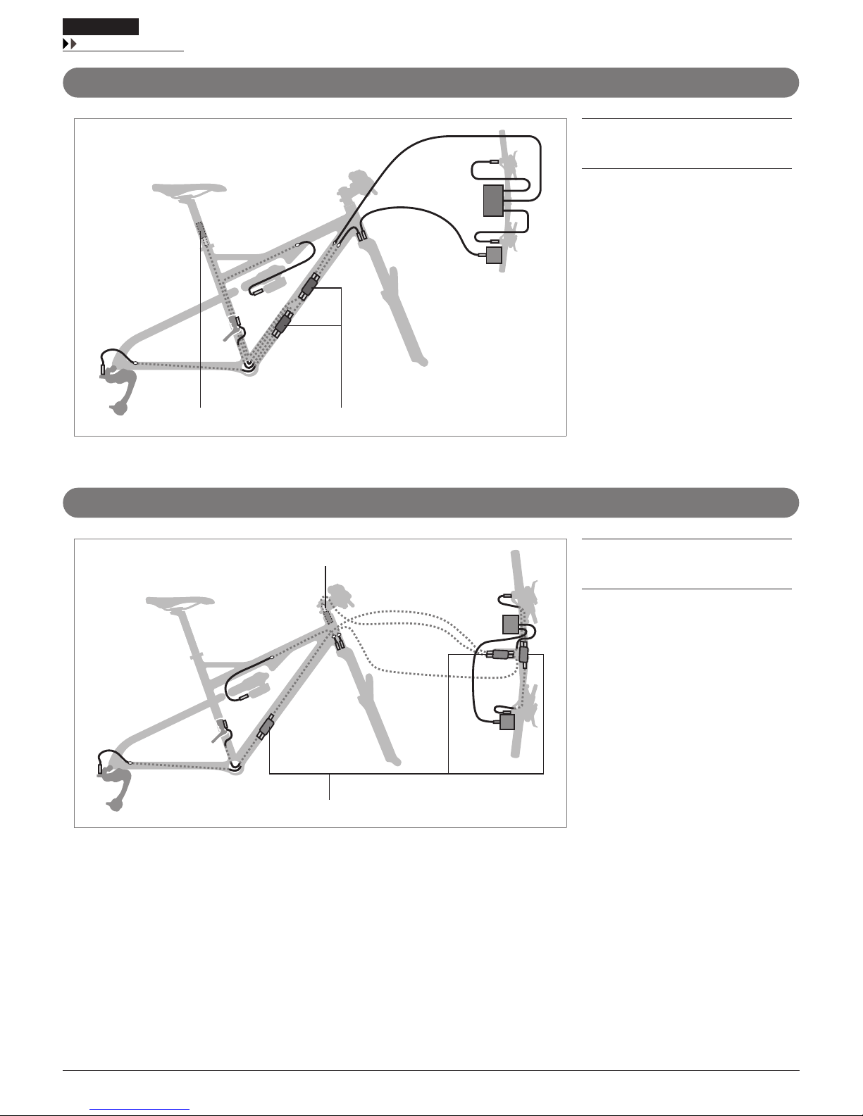
Electrical wiring diagram
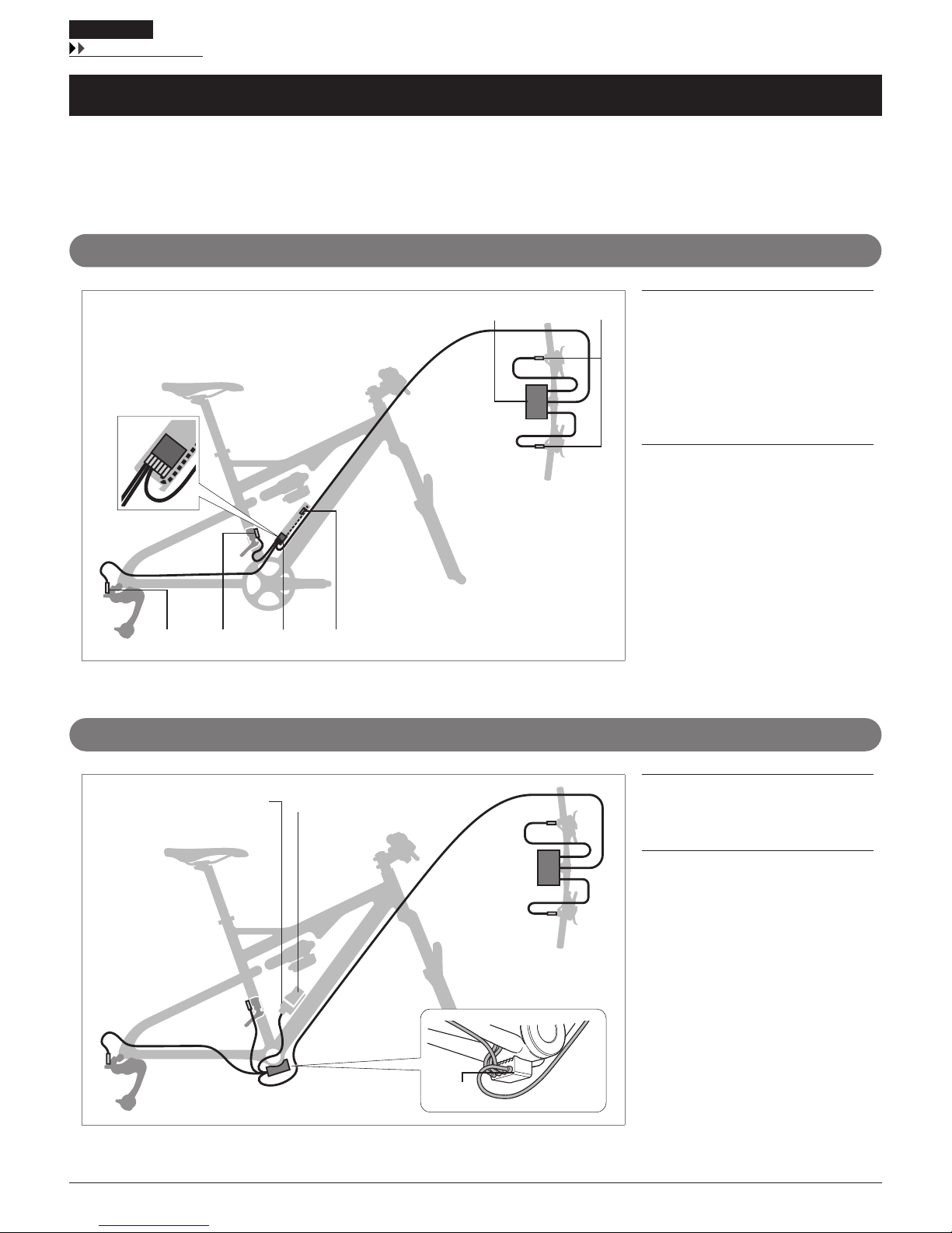
The connections shown below are only examples. The wiring method may differ depending on the type of frame. For details, contact a manufacturer of
completed bicycles.
External battery type (without suspension connection/SM-BTC1)
(C) (D) (F)
(A) (B)
(E)
(A) System information display /
junction (A)
(B) Shifting switch
(C) Rear derailleur
(D) Front derailleur
(E) Battery case SM-BTC1
(F) Battery SM-BTR2
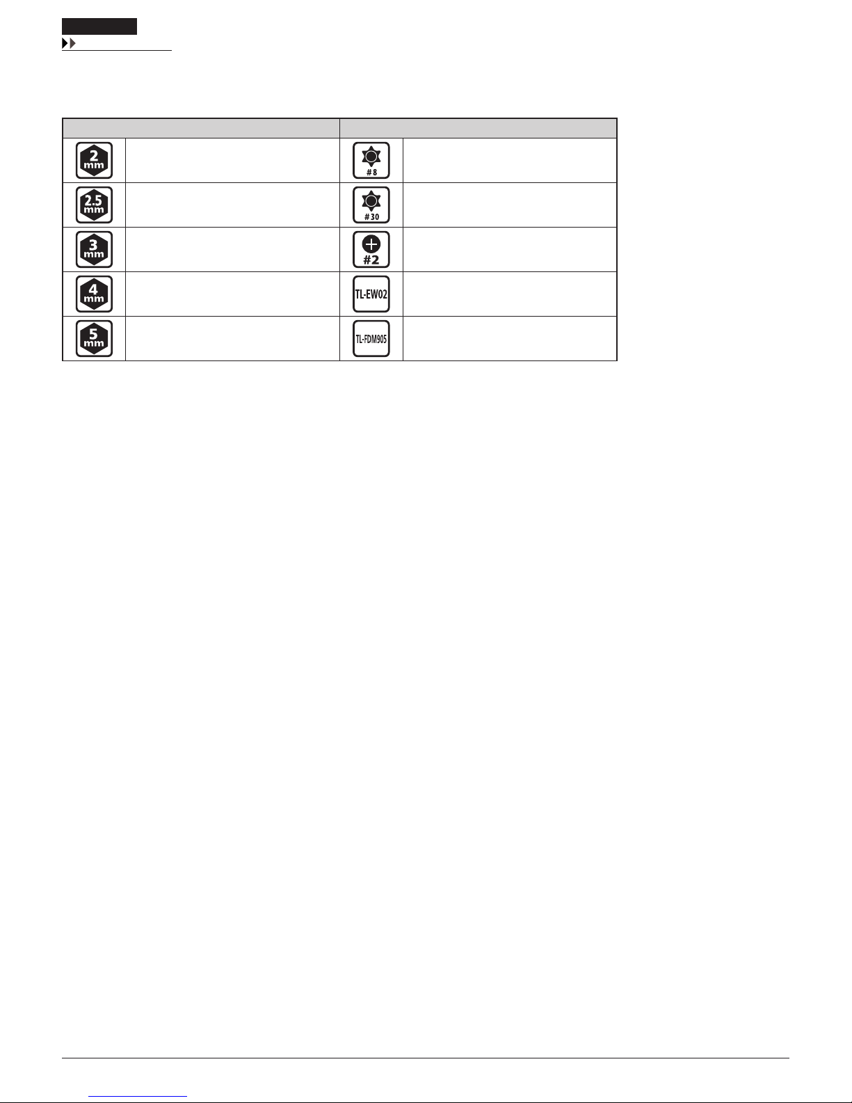
External battery type (without suspension connection/SM-JC40)
(C)
(B)(A)
(A) Battery mount
SM-BMR2
(B) Battery SM-BTR1
(C) Junction (B) SM-JC40
16
INSTALLATION
Electrical wiring diagram
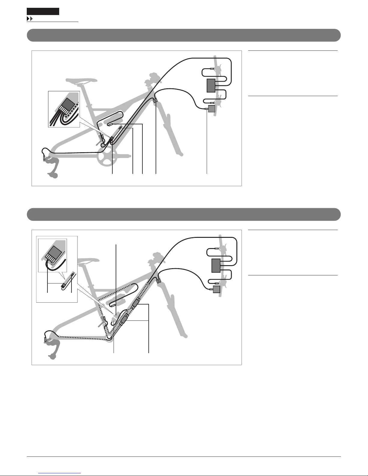
External battery type (with suspension connection/SM-BTC1)
(A) (C)(B) (E)(D)
(A) Battery case SM-BTC1
(B) Battery SM-BTR2
(C) Rear suspension motor unit
(D) Front suspension motor unit
(E) Suspension lock switch
External battery type (with suspension connection/SM-JC41)
(A)
(D)
(B)
(C) (E)
(A) Battery case SM-BTC1
(B) Battery SM-BTR2
(C) Battery mount
SM-BMR2
(D) Battery SM-BTR1
(E) Junction (B) SM-JC41
17
INSTALLATION
Electrical wiring diagram
Built-in battery type (seat post type)
(A)
(B)
(A) Battery SM-BTR2
(B) Junction (B) SM-JC41
Built-in battery type (head tube type)
(A)
(B)
(A) Battery SM-BTR2
(B) Junction (B) SM-JC41
18
INSTALLATION
List of tools to be used
List of tools to be used
The following tools are required to assemble the product.
Tool Tool
2 mm Allen key Hexalobular #8
2.5 mm Allen key Hexalobular #30
3 mm Allen key Screwdriver #2
4 mm Allen key TL-EW02
5 mm Allen key TL-FDM905
19
INSTALLATION
Installing the system information display
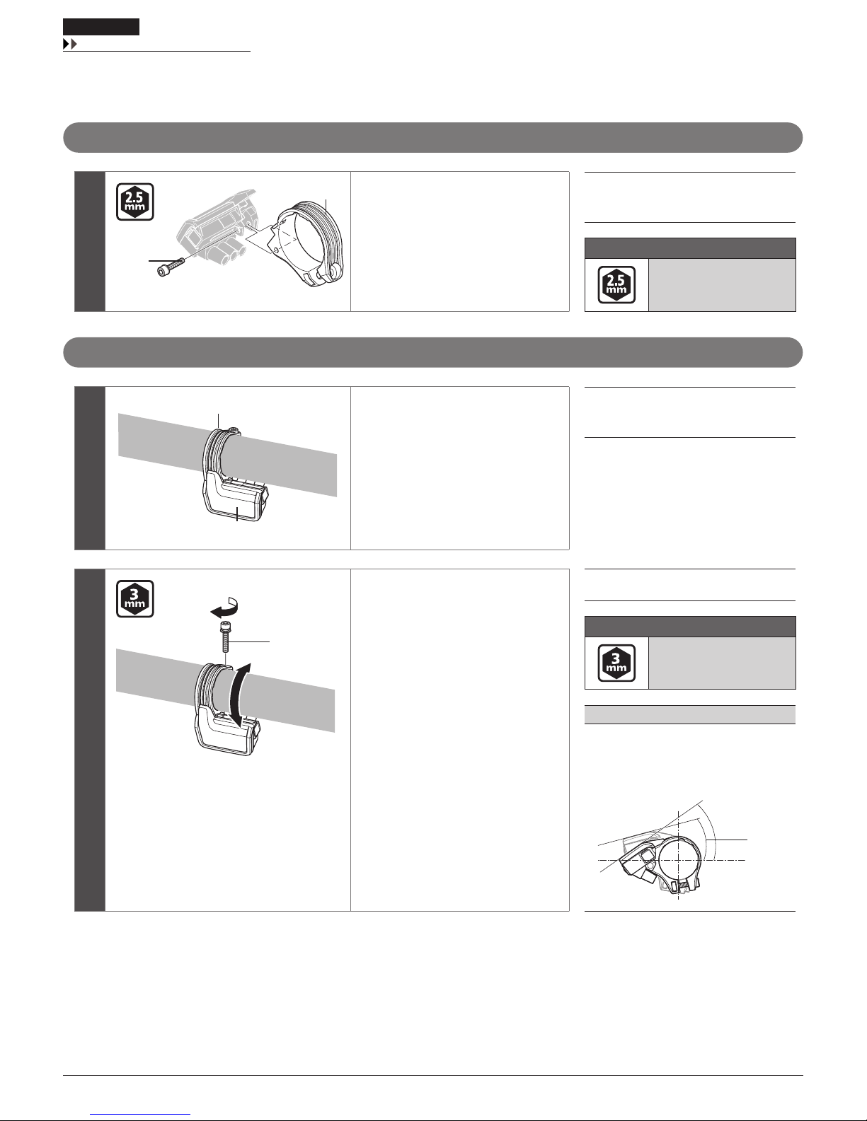
Installing the system information display
Install the system information display or junction (A) first.
Replacing the clamp band
(A)
(B)
If using a handlebar with a thick
diameter, reinstall it using the included
ϕ 35 clamp band.
Remove the case fixing bolt (A) with an
Allen key and replace the clamp band
(B).
(A) Case fixing bolt
(B) Clamp band
Tightening torque
0.6 N·m
{5.3 in. lbs.}
Installing to the handlebar
1
(B)
(A)
Insert the clamp band (B) of the system
information display (A) into the
handlebar.
(A) System information display
(B) Clamp band
2
(C)
Adjust the angle of the system
information display so that it is easy to
see, and then use an Allen key to tighten
the clamp bolt (C).
(C) Clamp bolt
Tightening torque
0.8 N·m
{7.0 in. lbs.}
NOTE
Recommended installation angle of the
information display:
The angle of the display is between 15° to 35°
to the horizontal.
35°
15°
20
INSTALLATION
Installation of junction (A)
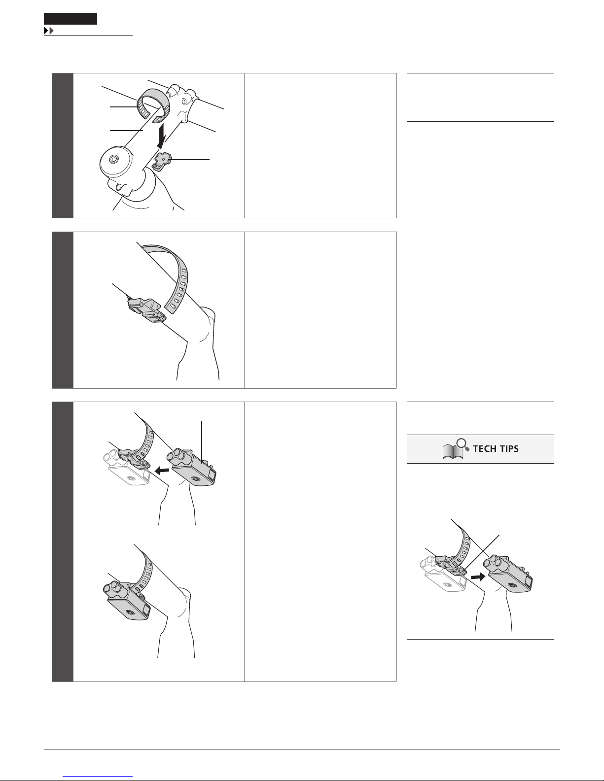
Installation of junction (A)
1
(A)
(C)
(B)
Using band (A) and hook (C) included
with SM-EW90, attach to stem (B).
(A) Band
(B) Stem
(C) Hook
2
Adjust according to the length of the
band and the thickness of the stem.
Hook the band on the hook and wind it
around the stem.
Pull on and secure the band.
3
(a)
(D)
Slide junction (A) (D) of SM-EW90 into
the rail section of the hook to install it.
(a) Finished image
(D) SM-EW90 Junction (A)
Removal
Pull up the release lever to slide junction (A)
in the direction of the arrow for removal.
Forcibly pulling up the release lever may
break the lever.
Release lever
21
INSTALLATION
Installation of the shifting switch
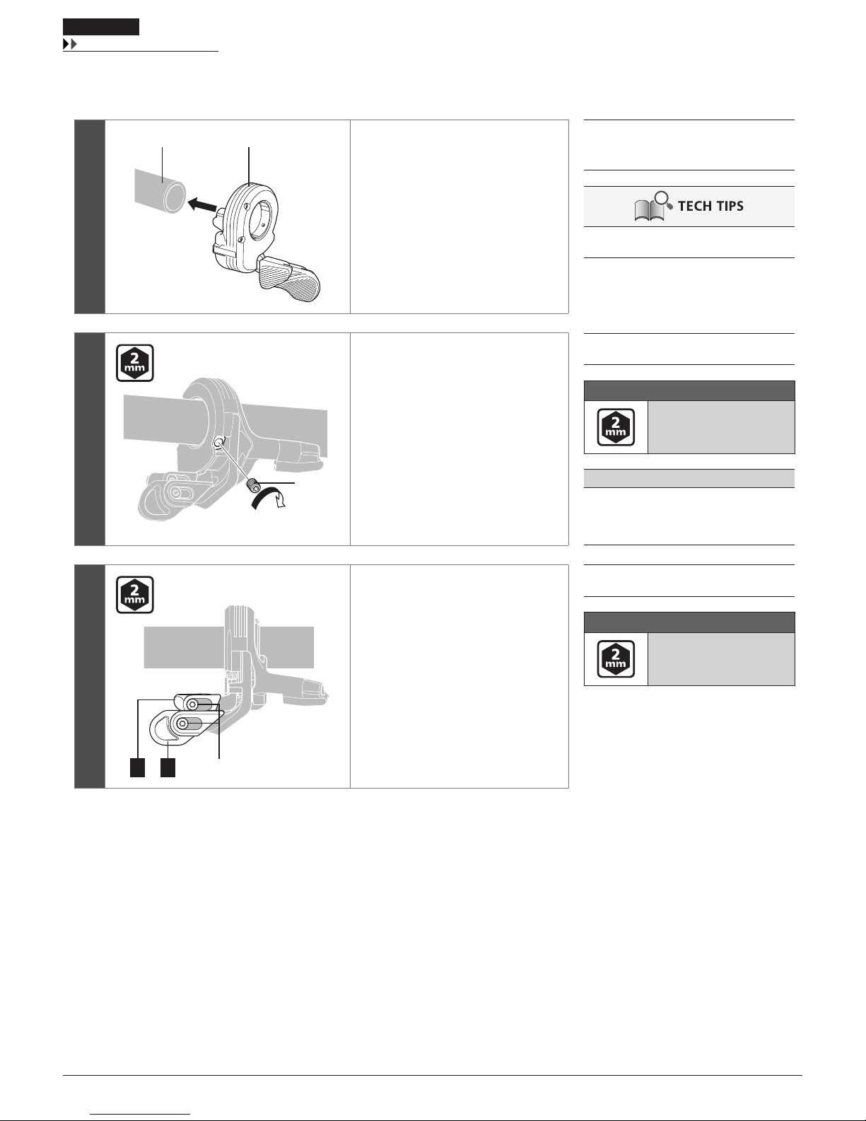
Installation of the shifting switch
The illustration shows the right-side lever.
1
(B)(A)
Pass the handlebar (A) through the
shifting switch (B).
(A) Handlebar
(B) Shifting switch
Applicable handlebars: ϕ22.2 - ϕ22.5
2
(C)
Adjust the attachment position and
angle, and then use an Allen key to
tighten the unit fixing bolt (C).
(C) Unit fixing bolt
Tightening torque
0.9 N·m
{7.9 in. lbs.}
NOTE
Attach the lever in a position where it will not
touch the brake lever when pushed all the
way in.
3
(D)
X Y
Adjust the positions of lever X and lever
Y.
Loosen the lever fixing bolt (D) using an
Allen key, and adjust the lever's position
so that it is easy to push.
After determining the position, tighten
to the designated torque.
(D) Lever fixing bolt
Tightening torque
0.5 - 0.7 N·m
{4.4 - 6.1 in. lbs.}
22
INSTALLATION
Installation of the front derailleur
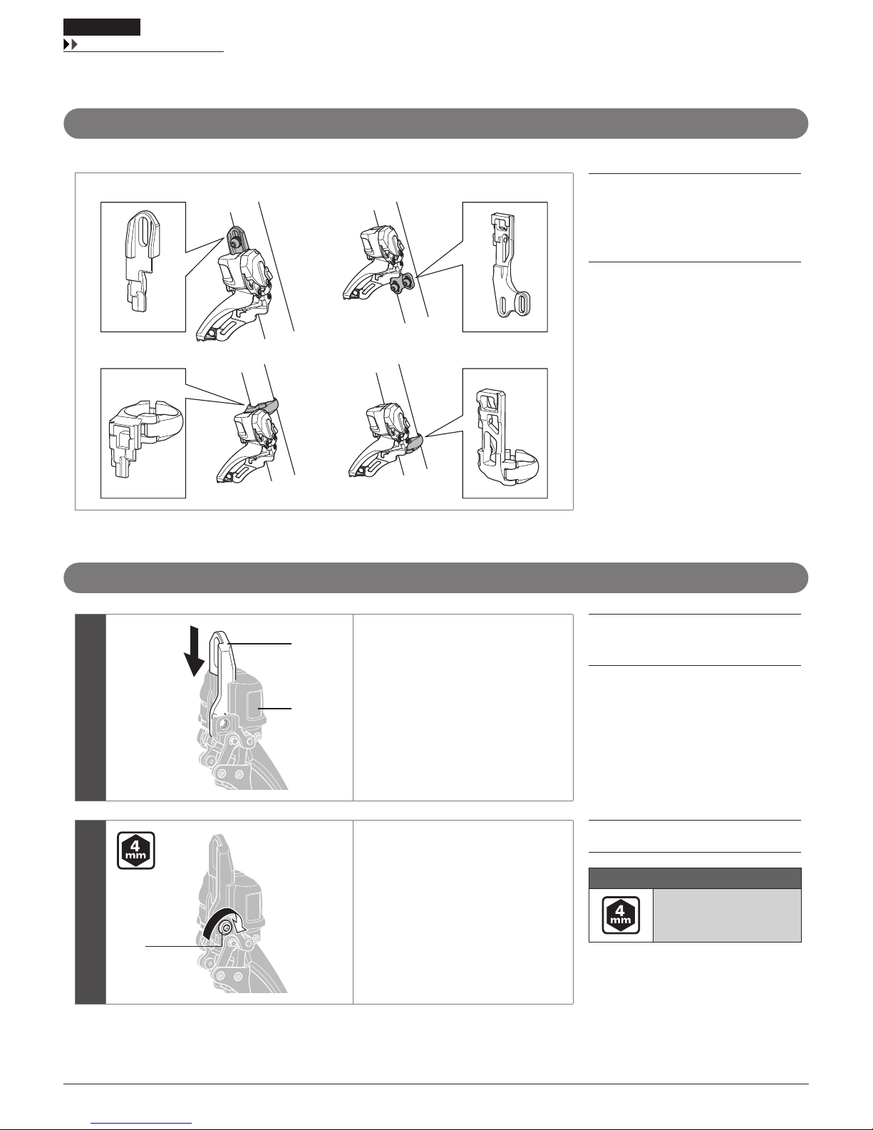
Installation of the front derailleur
Types of adapters
There are four types of front derailleur adapters. Choose one according to the shape of the frame.
(A) (B)
(C) (D)
(A) Type D
(B) Type E
(C) High clamp
(D) Low clamp
Installing the adapter
1
(A)
(B)
Slide the adapter (A) onto the front
derailleur (B) and insert it.
(A) Adapter
(B) Front derailleur
2
(C)
Install the bracket fixing bolt (C) at the
position specified in the illustration, and
tighten it with an Allen key.
*
Although the illustration shows a type
D adapter, the installation method is
the same for all adapters.
*
When replacing, reverse the
procedure.
(C) Bracket fixing bolt
Tightening torque
5 - 7 N·m
{44 - 61 in. lbs.}

23
INSTALLATION
Installation of the front derailleur
Installation on rear suspension types
NOTE
When installing components on the surface of
a carbon frame/handlebar, check the
tightening torque recommended by the
carbon frame or component manufacturer to
avoid carbon material damage due to
excessive tightening or insufficient
component holding force resulting from
insufficient tightening torque.
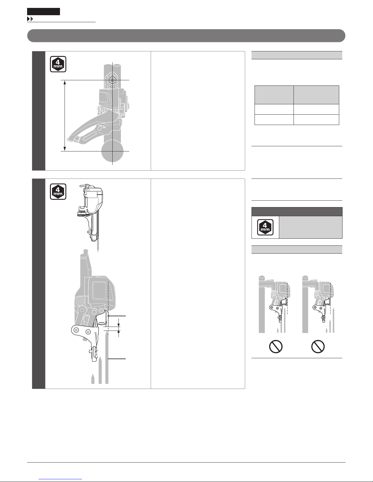
Adjust so that there is a clearance of 1 - 3 mm
between the chain guide outer plate and the
largest chainring. (Common to all types)
*
Bicycles with rear suspensions may be
positioned differently between when a
rider is off the bicycle and on the bicycle.
By referring to the illustration, perform
installation and SIS adjustment with the
bicycle fixed in a riding condition.
24
INSTALLATION
Installation of the front derailleur
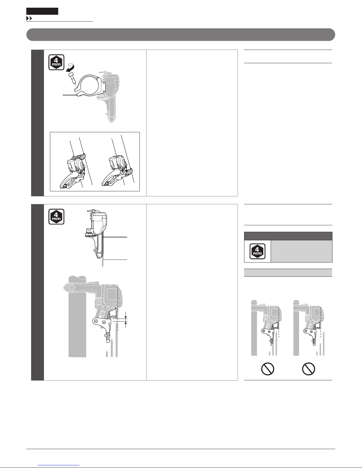
Band type
1
(A)
Install the front derailleur to the frame.
Temporarily fix the clamp bolt (A) with
an Allen key.
(A) Clamp bolt
2
(B)
(C)
(a)
Position the front derailleur so that the
flat part of the chain guide outer plate
(B) is directly above and parallel to the
largest chainring (C).
Check that the distance (a) from the tip
of the teeth of the largest chainring is 1
to 3 mm.
After adjusting the position, tighten the
clamp bolt to the designated torque.
(B) Chain guide outer plate
(C) Largest chainring
Tightening torque
5 - 7 N·m
{44 - 61 in. lbs.}
NOTE
Do not position the chain guide as shown in
the illustration.
25
INSTALLATION
Installation of the front derailleur
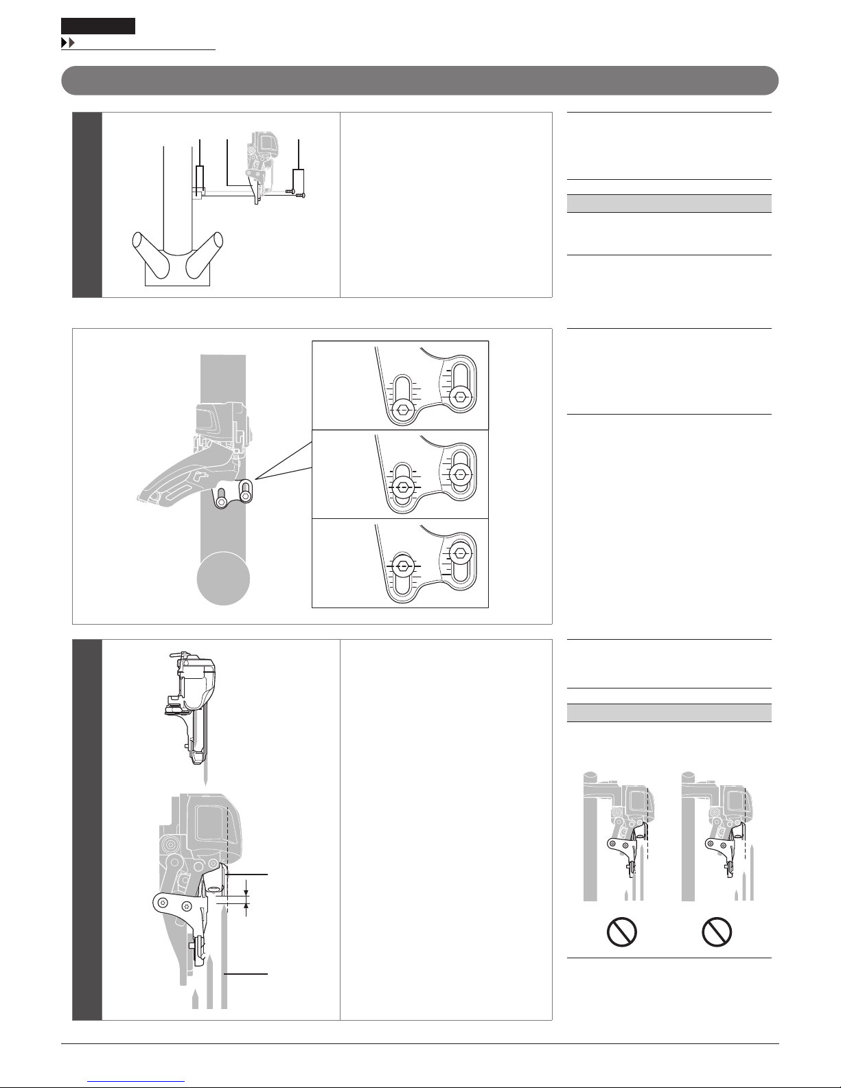
Type E
1
(C)
(A)
(B)
Install the front derailleur with the
bottom bracket mount fixing bolt (C).
Temporarily fix the bottom bracket
mount fixing bolt.
The fixing position varies with the
number of gear teeth used.
See below for the fixing position.
(A) BB mount
(B) Adapter
(C) BB mount fixing bolt
NOTE
Bottom bracket mount fixing bolts are not
supplied with Shimano products.
< Fixing position >
(D) (G)
(E)
(F)
(D) Double: largest chainring 38T
(E) Double: largest chainring 36T
(F) Double: largest chainring 34T
(G) Triple: largest chainring 40T
2
(H)
(I)
(a)
Position the front derailleur so that the
flat part of the chain guide outer plate
(H) is directly above and parallel to the
largest chainring (I).
Make sure that distance (a) from the tip
of the teeth of the largest chainring is 1
to 3 mm, then mount the fixing bolt.
If the distance does not fall within the
range, adjust the fixing position with the
elongated hole and fix the fixing bolt
again.
(H) Chain guide outer plate
(I) Largest chainring
NOTE
Do not position the chain guide as shown in
the illustration.
26
INSTALLATION
Installation of the front derailleur
Type D
1
H
Temporarily fix the front derailleur to
the frame.
NOTE
Compatible chainrings vary depending on
mount height H. Be sure to check the frame
dimensions.
H
Compatible largest
chainring
155.5 mm 34T - 38T
159.5 mm 36T - 38T
*
For triple chainrings, the front derailleur
can be mounted to both bases.
2
(A)
(B)
(a)
Position the front derailleur so that the
flat part of the chain guide outer plate
(A) is directly above and parallel to the
largest chainring (B).
Check that the distance (a) from the tip
of the teeth of the largest chainring is 1
to 3 mm.
After adjusting the position, tighten the
clamp bolt to the designated torque.
(A) Chain guide outer plate
(B) Largest chainring
Tightening torque
5 - 7 N·m
{44 - 61 in. lbs.}
NOTE
Do not position the chain guide as shown in
the illustration.
27
INSTALLATION
Installation of the rear derailleur
Installation of the rear derailleur
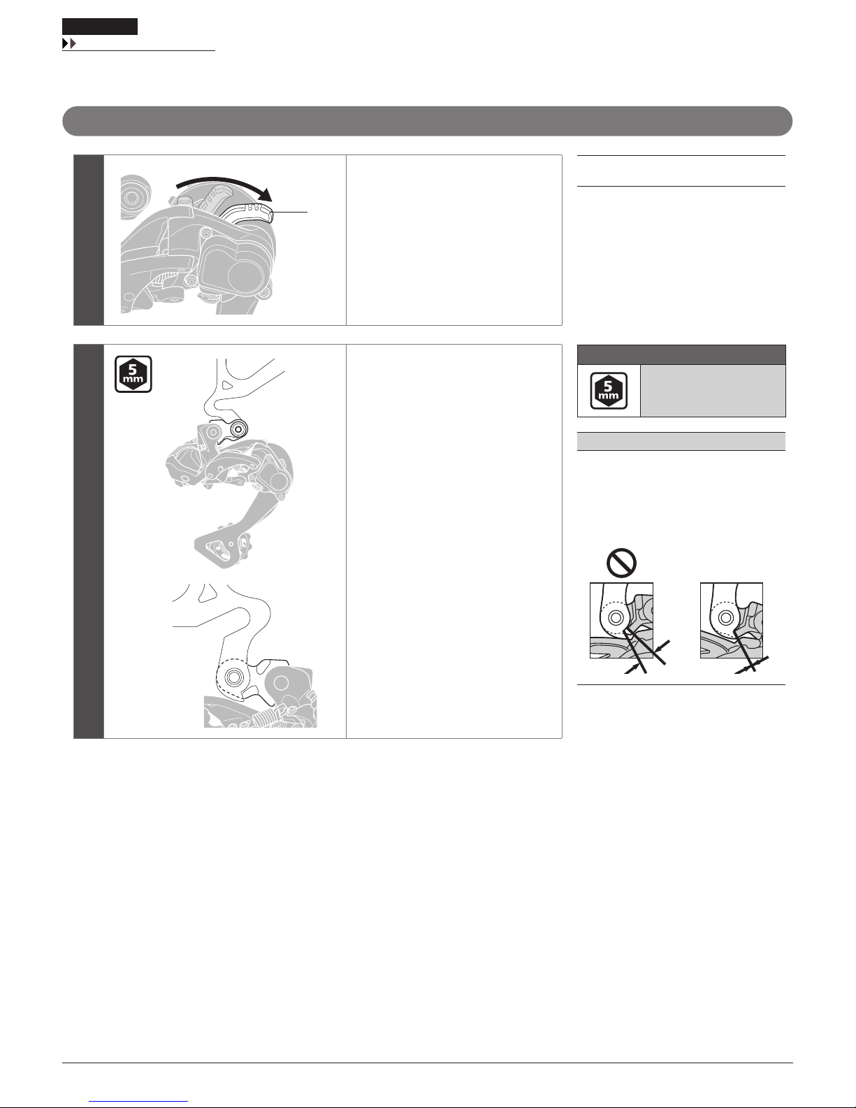
Standard type
1
(a)
(b)
(A)
Make sure that the lever switch (A) is in
the OFF position.
If the lever switch is in the ON position,
be sure to move it to the OFF position.
(a) ON
(b) OFF
(A) Lever switch
2
Install the rear derailleur.
Tightening torque
8 - 10 N·m
{70 - 87 in. lbs.}
NOTE
Periodically check that there is no gap
between the rear dropout and bracket as
shown in the illustration. Any gap between
them may interfere with shifting
performance.
OK
28
INSTALLATION
Installation of the rear derailleur
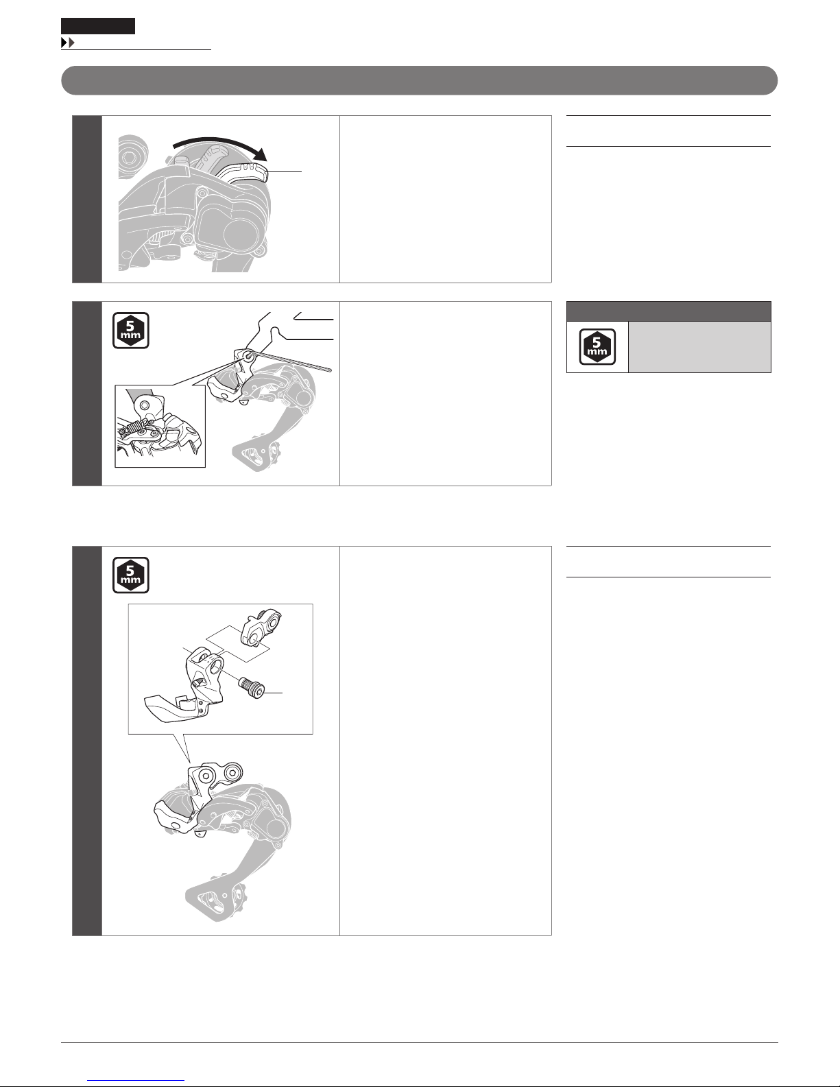
Direct mount type
1
(a)
(b)
(A)
Make sure that the lever switch (A) is in
the OFF position.
If the lever switch is in the ON position,
be sure to move it to the OFF position.
(a) ON
(b) OFF
(A) Lever switch
2
Install the direct-mount rear derailleur.
Direct-mount rear derailleurs can only be
installed to frames supporting direct
mounting.
Tightening torque
8 - 10 N·m
{70 - 87 in. lbs.}
< Replacing with a direct mount type >
(A)
Remove the bracket axle (A).
(A) Bracket axle
To be continued on next page
29
INSTALLATION
Connection of the electric wires
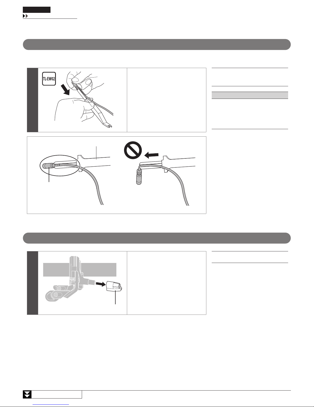
Connection of the electric wires
Precautions for connecting electric wires
Use the Shimano original tool for installation and removal of the electric wire. When installing electric wires, do not forcibly bend the plug part. It may
result in a poor contact. When connecting electric wires, push them in until you feel and hear a click.
Set so that the projection on the
connector is aligned with the groove on
the narrow end.
(A) Shimano original tool TL-EW02
(B) Plug
NOTE
This is a small waterproof connector. Do not
repeat connecting and disconnecting it. The
waterproof section or the connecting section
may become worn or deformed, and the
function may be affected.
(B)
(A)
Connecting the shifting switch
1
(A)
Remove the cable cap (A) from the
shifting switch.
(A) Cable cap
 Loading...