

Shimano ULTEGRA SL-BS78 - TECHNICAL,Dura-Ace SL-BS78 Service Instructions Manual
General Safety Information
t
WARNING
– To avoid serious injuries:
Obtain and read the service instructions carefully
prior to installing the parts. Loose, worn, or damaged
parts may cause serious injury to the rider.
We strongly recommend only using genuine
Shimano replacement parts.
Read these Technical Service Instructions carefully,
and keep them in a safe place for later reference.
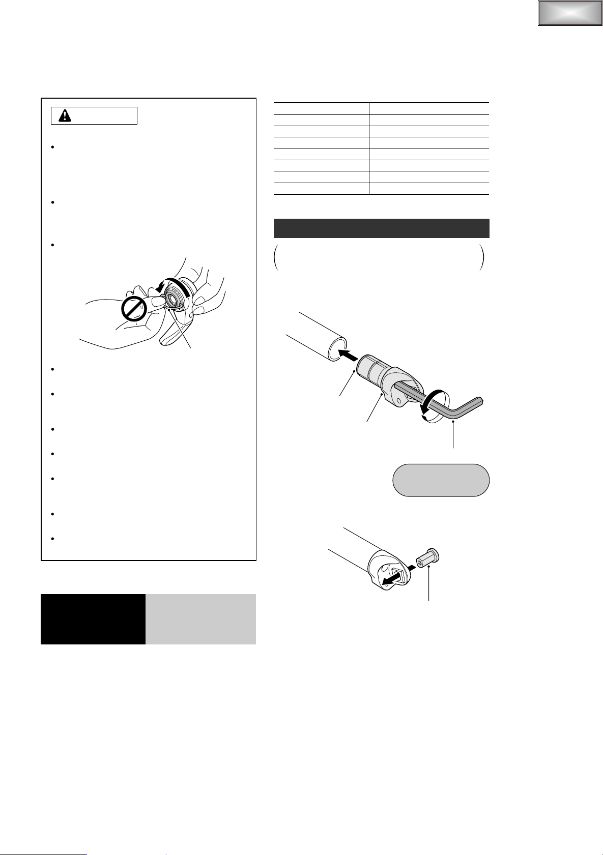
NOTE:
Do not turn the ring until the lever has been secured
to the body unit.
Ring
For smooth operation, use the specified outer casing
and bottom bracket cable guide.
Because the high cable resistance of a frame with
internal cable routing would impair the SIS function,
this type of frame should not be used.
The sliding surfaces of the inner cable and outer
casing should be greased before use.
The shifting lever can be installed to handlebars with
diameters of 19.0 – 22.0 mm.
Operation of the levers related to gear shifting
should be made only when the front chainwheel is
turning.
Parts are not guaranteed against natural wear or
deterioration resulting from normal use.
For any questions regarding methods of handling or
maintenance, please contact the place of purchase.
In order to realize the best performance, we recommend
that the following combination be used.
Series
Shifting lever
Rear derailleur
Front derailleur
Outer casing
Inner cable
Bottom bracket guide
Sprockets
DURA-ACE
SL-BS78
RD-7800
FD-7800
SP41 sealed outer casing
1.2 mm dia. (stainless steel)
SM-SP17
10
Installation of the lever
The illustration shows an explanation of the case
where the shifting lever is installed to drop handlebars.
Install the front lever in the same way.
Attach the body unit to the handlebar, and then use a
1.
6 mm Allen key to turn the body fixing bolt
counterclockwise to tighten it.
Body fixing bolt
Body unit
6 mm Allen key
Tightening torque:
5 – 6 Nm
{43 – 52 in. lbs.}
Install the lever boss to the body unit.
2.
SI-6J60A
Bar End
SL-BS78
Shifting Lever
Technical Service Instructions
Lever boss
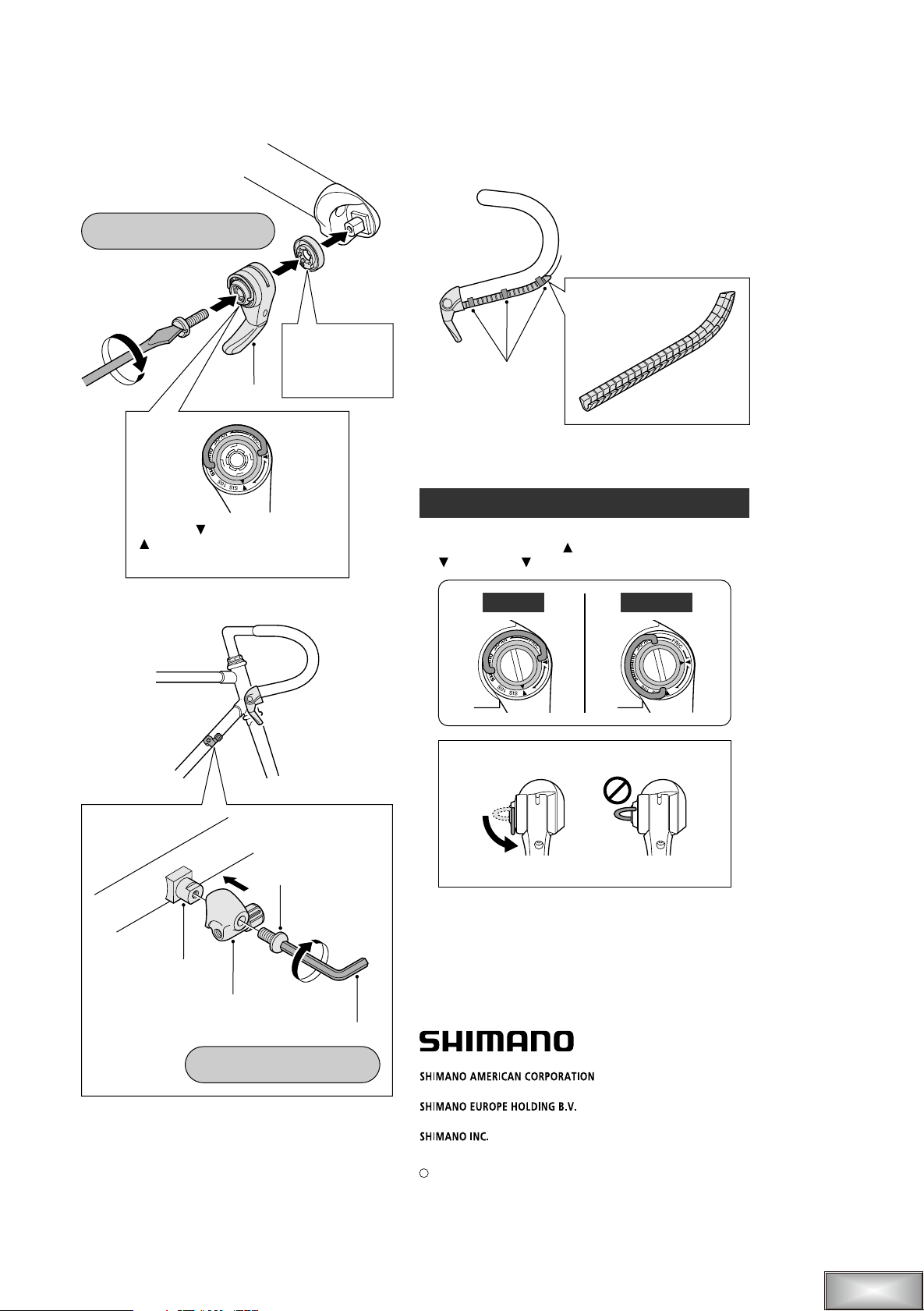
Install the lever to the body unit.
t
3.
Tightening torque:
2.5 – 3 Nm {21 – 26 in. lbs.}
With the outer casing placed along the handlebar, cover
5.
the outer casing with the outer casing guide, and then
use tape or similar material to provisionally attach it to
the handlebar.
M5
Set so that the
projection
faces
Lever grip
Align the SIS mark and the red
mark, and then set so that the
lever grip faces downward.
Install the outer casing stopper to the brazed-on boss.
4.
downward.
Outer casing guide
Tape
Wrap the handlebar with bar tape.
6.
SIS operation
Turn the ring to select either SIS or friction.
Turn the ring until the red mark is correctly aligned with
the SIS or FRIC mark.
FrictionSIS
After making a selection, be sure to fold the ring
downward.
Brazed-on boss (M5)
Outer casing stopper (SM-CS50)
Tightening torque:
1.5 – 2 Nm {13 – 17 in. lbs.}
Stopper fixing bolt
3 mm Allen key
OK
These service instructions are printed on recycled paper.
Please note: Specifications are subject to change for improvement without
notice. (English)
One Holland, Irvine, California 92618, U.S.A. Phone: +1-949-951-5003
Industrieweg 24, 8071 CT Nunspeet, The Netherlands Phone: +31-341-272222
3-77 Oimatsu-cho, Sakai, Osaka 590-8577, Japan
C
Jul. 2003 by Shimano Inc. PIT. SZK. Printed in Japan
Not OK
®
 Loading...