

Page 1
SL-RS43-7
1. Top adjustment
Turn the top adjustment screw to adjust so that the guide pulley is
below the outer line of the smallest sprocket when looking from the
rear.
1 2
1
2
Guide pulley
Outer line of smallest
sprocket
Top
adjustment
screw
RD-TX70/ TX50 / TX30
Cable securing and stroke adjustment
•If routing the casing downward:
(The chain should be on the largest chainring and on the largest
sprocket.)
Set the length of the outer casing so that it describes a smooth arc,
and so that the link stops in a position where there is a small gap
between the link and the link stop.
Place the outer casing so that it does not touch the basket and
mudguard, otherwise it may cause a problem with the performance of
the derailleur.
Set the outer casing (RD-TX70/RD-TX50/RD-FT30) so that its
length is as follows.
•If routing the casing upward:
(The chain should be on the largest chainring and on
the largest sprocket.)
Add 10 mm to the length of the outer casing from the
end that is inserted into the outer casing holder to the
end which is inserted into the link.
Outer casing
holder
Link
Largest
sprocket
Largest
chainring
Link stop
Link
Chain position
Largest
sprocket
Largest
chainring
Chain position
L
Connect the inner cable to the
derailleur as shown in the illustration.
Inner cable
< RD-TX70 / RD-TX50 / RD-FT30 >
max.
angle
max.
angle
RD-FT30
RD-FT30
RD-TY18
RD-TY18
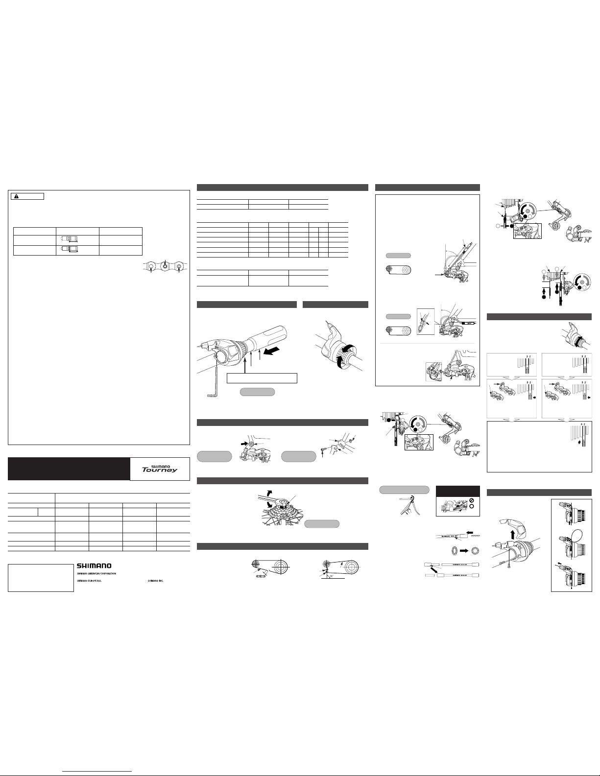
Mounting the shifting lever
Tightening torque:
2 N·m {18 in. lbs.}
Handlebar
Half grip
Install the brake lever in a position where it will not obstruct brake
operation.
Do not use in a combination which causes brake operation to be
obstructed.
Gear shifting operation
Pedaling becomes
heavier
Pedaling becomes
lighter
Model number
Gears
SL-RS43-7
SIS 7 - gears
Shifting lever
Specifications
SL-RS43-6
SIS 6 - gears
Tooth combination
Gears
14, 16, 18, 20, 22, 24, 34T
14, 16, 18, 20, 22, 24, 28T
13, 15, 17, 19, 21, 24, 34T
7
Type
Gears
Total capacity
Rear largest sprocket
Rear smallest sprocket
SS
7 / 6
17T
28T
11T
Front chainwheel tooth difference
––
RD-FT30
Model number
Rear derailleur
Sprocket tooth configurations
14, 16, 18, 21, 24, 34T
14, 16, 18, 21, 24, 28T
6
GS
6
34T
28T
14T
20T
SS
6
28T
28T
14T
13T
RD-TY18
Smartcage
7 / 6
43T
28-34T
11T
20T
RD-TX30
Smartcage
7 / 6
43T
28-34T
11T
20T
RD-TX50
Smartcage
7 / 6
43T
28-34T
11T
20T
RD-TX70
SIS40
7 - gears
SIS40
6 - gears
CN-HG50
SM-SP18/BT18
CN-HG50
SM-SP18/BT18
CN-HG50
SM-SP18/BT18
CN-HG50
SM-SP18/BT18
SIS40
MF-TZ37/HG50
MF-HG37/TZ07
MF-HG40-6/HG22
MF-TZ06
MF-TZ37/TZ07
MF-HG50
MF-HG40-6/HG22
MF-TZ06
SL-RS43-6 SL-RS43-7 SL-RS43-6
7 - gears
RD-TX70/RD-TX50
RD-TX30
RD-TX70/RD-TX50
RD-TX30/RD-TY18
RD-TX70/RD-TX50
RD-TX30
RD-FT30
RD-TX70/RD-TX50
RD-TX30/RD-TY18
RD-FT30
SIS40
6 - gears
Right
Multiple freewheel
Chain
Bottom bracket cable guide
Shifting lever
Rear derailleur
Outer casing
In order to realize the best performance, we recommend that the following combination be used.
Series
Gears
Tourney
• Use neutral detergent to clean the chain. Do not use alkali-based or acid based detergent such as rust cleaners as it may
result in damage and/or failure of the chain.
• Use the reinforced connecting pin only for connecting the narrow type of chain.
• There are two different types of reinforced connecting pins available. Be sure to check the table below before selecting
which pin to use. If connecting pins other than reinforced connecting pins are used, or if a reinforced connecting pin or tool
which is not suitable for the type of chain is used, sufficient connection force may not be obtained, which could cause the
chain to break or fall off.
• If it is necessary to adjust the length of the chain due to a change in the number of sprocket
teeth, make the cut at some other place than the place where the chain has been joined
using a reinforced connecting pin or an end pin. The chain will be damaged if it is cut at a
place where it has been joined with a reinforced connecting pin or an end pin.
• Check that the tension of the chain is correct and that the chain is not damaged. If the
tension is too weak or the chain is damaged, the chain should be replaced. If this is not
done, the chain may break and cause serious injury.
• Check that the wheels are fastened securely before riding the bicycle. If the wheels are loose in any way, they may come off
the bicycle and serious injury may result.
• Obtain and read the service instructions carefully prior to installing the parts. Loose, worn, or damaged parts may cause
injury to the rider.
We strongly recommend only using genuine Shimano replacement parts.
• Read these Technical Service Instructions carefully, and keep them in a safe place for later reference.
Note
• The reinforced connecting pins cannot be used with the UG chain, otherwise the connections will not move properly and
noise will occur.
• If gear shifting operations do not feel smooth, wash the derailleur and lubricate all moving parts.
• If the amount of looseness in the links is so great that adjustment is not possible, you should replace the derailleur.
• You should periodically clean the derailleur and lubricate all moving parts (mechanism and pulleys).
• If gear shifting adjustment cannot be carried out, check the degree of parallelism at the rear end of the bicycle. Also check if
the cable is lubricated and if the outer casing is too long or too short.
• If you hear abnormal noise as a result of looseness in a pulley, you should replace the pulley.
• If the wheel becomes stiff and difficult to turn, you should lubricate it with grease.
• Do not apply any oil to the inside of the hub, otherwise the grease will come out.
• You should periodically wash the sprockets in a neutral detergent and then lubricate them again. In addition, cleaning the
chain with neutral detergent and lubricating it can be a effective way of extending the useful life of the sprockets and the
chain.
• If the chain keeps coming off the sprockets during use, replace the sprockets and the chain.
• Use an outer casing which still has some length to spare even when the handlebars are turned all the way to both sides.
Furthermore, check that the shifting lever does not touch the bicycle frame when the handlebars are turned all the way.
• Grease the inner cable and the inside of the outer casing before use to ensure that they slide properly.
• Use a frame with internal cable routing is strongly discouraged as it has tendencies to impair the SIS shifting function due to
its high cable resistance.
• Operation of the levers related to gear shifting should be made only when the front chainwheel is turning.
• For smooth operation, use the specified outer casing and bottom bracket cable guide.
• To ensure the best performance, be sure to use only the specified type of chain. The wide type chain cannot be used.
• For maximum performance we highly recommend Shimano lubricants and maintenance products.
• Parts are not guaranteed against natural wear or deterioration resulting from normal use.
• For any questions regarding methods of installation, adjustment, maintenance or operation, please contact a professional
bicycle dealer.
Technical Service Instructions
SI-6KP0A
Rear Drive System
Leave a gap of 0.5 mm between the Revo-shift
lever and the half grip.
Loosen the outer casing
adjustment barrel until the chain
touches the 3rd sprocket and
makes noise. (counter clockwise)
Tighten the outer cable adjusting
barrel until the chain returns to
the 2nd sprocket. (clockwise)
Best setting
The best setting is when the shifting lever is operated
just enough to take up the play and the chain touches
the 3rd sprocket and makes noise.
* Return the lever to its original position (the position
where the lever is at the 2nd sprocket setting and it has
been released) and then turn the crank arm clockwise.
If the chain is touching the 3rd sprocket and making
noise, turn the outer casing adjustment barrel
clockwise slightly to tighten it until the noise stops and
the chain runs smoothly.
Operate lever to change gears, and check that no
noise occurs in any of the gear positions.
Operate the shifting lever several times to move
the chain to the 2nd sprocket. Then, while
pressing the lever just enough to take up the play
in the lever, turn the crank arm.
SIS Adjustment
For the best SIS performance, periodically lubricate all power-transmission
parts.
When shifting to 3rd
Play
When no sound at
all is heard
adjustment
ballel
RD-TX70/50
RD-FT30
RD-TX30
adjustment
ballel
RD-TX70/50
RD-FT30
RD-TX30
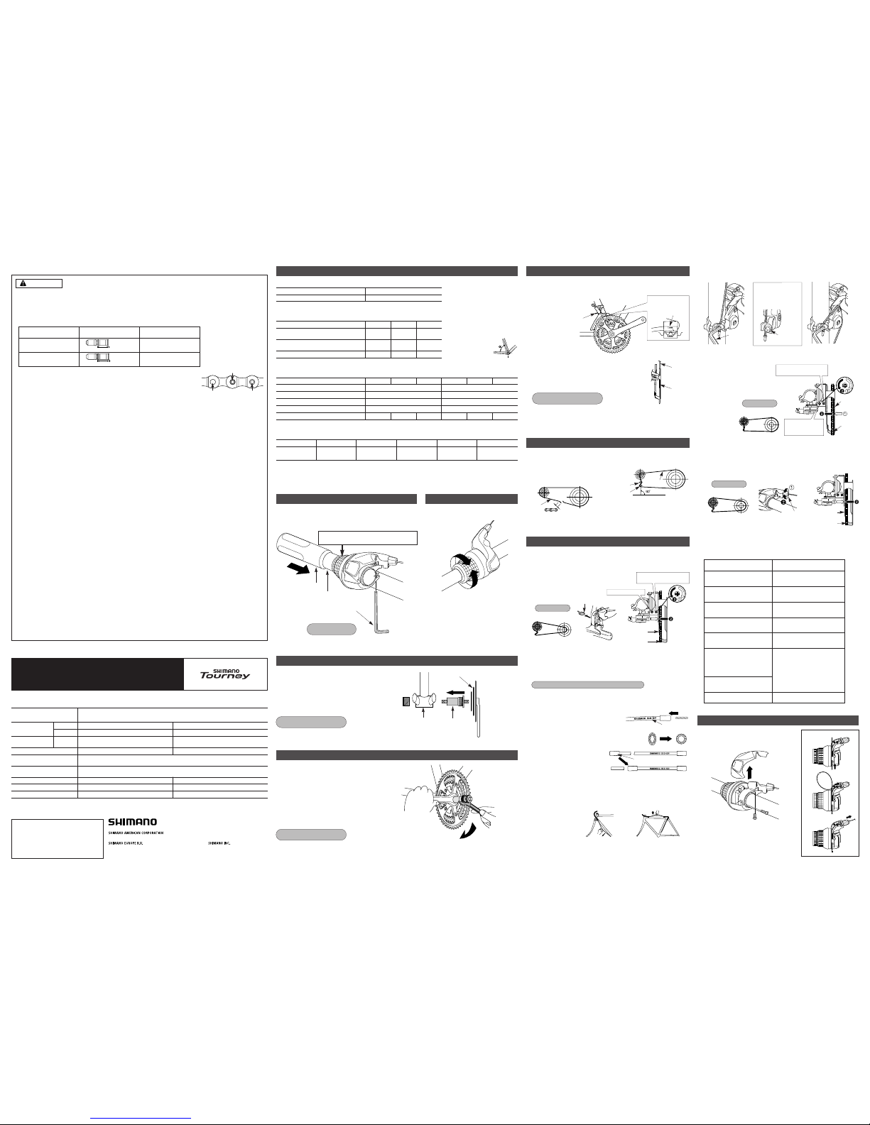
Replacing the inner cable
➀
➁
➂
Replace the inner cable by carrying out
steps
➀
to ➂as shown in the illustrations.
General Safety Information
Chain
WARNING
Chain tool
9-speed super narrow
chain such as
CN-7701 / CN-HG93
8-/ 7-/ 6-speed narrow
chain such as
CN-HG50 / CN-IG51
Reinforced connecting pin
TL-CN32 / TL-CN23
TL-CN32 / TL-CN23
Silver
Black
Reinforced Connecting Pin
End Pin Link Pin
6.5mm
7.1mm
One Holland, Irvine, California 92618, U.S.A. Phone: +1-949-951-5003
Industrieweg 24, 8071 CT Nunspeet, The Netherlands Phone: +31-341-272222
3-77 Oimatsu-cho, Sakai, Osaka 590-8577, Japan
Please note: specifications are subject to change for improvement without notice. (English)
©Apr. 2005 by Shimano Inc. XBC SZK Printed in Singapore
This service instruction explains how to use
and maintain the Shimano bicycle parts
which have been used on your new bicycle.
For any questions regarding your bicycle or
other matters which are not related to
Shimano parts, please contact the place of
purchase or the bicycle manufacturer.
Pull
Groove
Note: Be sure that the cable is
securely in the groove.
Tightening torque:
5 - 7 N·m {44 - 60 in. lbs.}
2. Connection and securing of cable
Connect the cable to the rear derailleur and, after taking up the initial
slack in the cable, reattach to the rear derailleur as shown in the
illustration.
Secure the cable by pulling it with pliers with a force of 5 - 10 kg.
RD-TX70/ TX50 / TX30
1
2
1 2
Guide pulley
Low adjustment
screw
Largest
sprocket
3. Low adjustment
Turn the low adjustment screw so that the guide pulley moves to a
position directly below the
largest sprocket.
Mount the chain on the smallest chainring and the largest sprocket,
and turn the crank arm
backward. Then turn the Btension adjustment screw to
adjust the guide pulley as close
to the sprocket as possible but
not so close that it touches.
Next, set the chain to the
smallest sprocket and repeat the
above to make sure that the
pulley does not touch the
sprocket.
1
2
1 2
2
1
B-tension
adjustment screw
Largest sprocket Smallest sprocket
4. How to use the B-tension adjustment screw
< RD-TX70 / RD-TX50 / RD-TX30 >
3 mm Allen Key
Chain length
Chain
Largest
chainring
Largest
chainring
< GS > < SS >
Smallest
sprocket
Largest
chainring
Chain
Guide pulley
Tension pulley
Right angle to the ground
Add 2 links (with the chain on
both the largest sprocket and
the largest chainring)
Bracket type
Frame
Bracket bolt
Bracket nut
Bracket
Tightening torque:
3 - 4 N·m
{26 - 34 in. lbs.}
Freewheel removal tool
TL-FW30
Tightening torque:
30 N·m {260 in. lbs.}
Installation of the freewheel
To disassemble
To install
Installation of the rear derailleur
Direct-mount type
Push in and tighten
Tightening torque:
8 - 10 N·m
{70 - 86 in. lbs.}
5 mm Allen Key
Attach the same outer end
cap to the cut end of the outer
casing.
Outer end cap
Cutting the outer casing
When cutting the outer casing, cut the opposite
end to the end with the marking. After cutting the
outer casing, make the end round so that the
inside of the hole has a uniform diameter.
Inserting the inner cable
Insert the inner cable into the outer casing from the end with the
marking on it. Apply grease from the end with the marking in
order to maintain cable operating
efficiency.
Marking
Page 2
Mounting the shifting lever
Install the brake lever in a position where it will not obstruct brake
operation.
Do not use in a combination which causes brake operation to be
obstructed.
Gear shifting operation
Model number
Gears
SL-RS43-L
SIS 3 - gears
Shifting lever
Specifications
CN-HG50
SM-SP18/BT18
CN-HG50
SM-SP18/BT18
SIS40
BB-UN26 BB-UN26
SL-RS43-L SL-RS43-L
7 - gears
FD-C051/FD-TY30
FD-C050/FD-TY10
SIS40
6 - gears
3 - gears 3 - gears
Left
Bottom bracket
Chain
Bottom bracket cable guide
Shifting lever
Front derailleur
Outer casing
In order to realize the best performance, we recommend that the following combination be used.
Series
Gears
Tourney
FC-TX70/TC-TX71/FC-TY33
FC-TS38A/FC-TY40/FC-TS32
Front chainwheel
• Use neutral detergent to clean the chain. Do not use alkali-based or acid based detergent such as rust cleaners as it may
result in damage and/or failure of the chain.
• Use the reinforced connecting pin only for connecting the narrow type of chain.
• There are two different types of reinforced connecting pins available. Be sure to check the table below before selecting
which pin to use. If connecting pins other than reinforced connecting pins are used, or if a reinforced connecting pin or tool
which is not suitable for the type of chain is used, sufficient connection force may not be obtained, which could cause the
chain to break or fall off.
• If it is necessary to adjust the length of the chain due to a change in the number of sprocket
teeth, make the cut at some other place than the place where the chain has been joined
using a reinforced connecting pin or an end pin. The chain will be damaged if it is cut at a
place where it has been joined with a reinforced connecting pin or an end pin.
• Be careful not to let the cuffs of your clothes get caught in the chain while riding, otherwise
you may fall off the bicycle.
• Check that the tension of the chain is correct and that the chain is not damaged. If the tension is too weak or the chain is
damaged, the chain should be replaced. If this is not done, the chain may break and cause serious injury.
• Check that there are no cracks in the crank arms before riding the bicycle. If there are any cracks, the crank arm may break
and you may fall off the bicycle.
• Obtain and read the service instructions carefully prior to installing the parts. Loose, worn, or damaged parts may cause
injury to the rider.
We strongly recommend only using genuine Shimano replacement parts.
• Read these Technical Service Instructions carefully, and keep them in a safe place for later reference.
Note
• The reinforced connecting pins cannot be used with the UG chain, otherwise the connections will not move properly and
noise will occur.
• Apply grease to the thread section of the bottom bracket and to the inside thread of the adapter before installing the bottom
bracket.
• In addition, if pedaling performance does not feel normal, check this once more.
• Check that there is no looseness in any joints or connections before riding the bicycle. (BB-FC, FC-PD)
• Do not wash the bottom bracket with high-pressure jets of water.
• If you feel any looseness in the bottom bracket axle, the bottom bracket should be replaced.
• If gear shifting operations do not feel smooth, wash the derailleur and lubricate all moving parts.
• If the amount of looseness in the links is so great that adjustment is not possible, you should replace the derailleur.
• You should periodically wash the chainrings in a neutral detergent and then lubricate them again. In addition, cleaning the
chain with neutral detergent and lubricating it can be a effective way of extending the useful life of the chainrings and the
chain.
• If the chain keeps coming off the chainrings during use, replace the chainrings and the chain.
• Use an outer casing which still has some length to spare even when the handlebars are turned all the way to both sides.
Furthermore, check that the shifting lever does not touch the bicycle frame when the handlebars are turned all the way.
• Grease the inner cable and the inside of the outer casing before use to ensure that they slide properly.
• Operation of the levers related to gear shifting should be made only when the front chainwheel is turning.
• For smooth operation, use the specified outer casing and bottom bracket cable guide.
• To ensure the best performance, be sure to use only the specified type of chain. The wide type chain cannot be used.
• For maximum performance we highly recommend Shimano lubricants and maintenance products.
• Parts are not guaranteed against natural wear or deterioration resulting from normal use.
• For any questions regarding methods of installation, adjustment, maintenance or operation, please contact a professional
bicycle dealer.
Technical Service Instructions
SI-6KS0A
Front Drive System
Chain length
Chain
Largest
chainring
Largest
chainring
< GS > < SS >
Smallest
sprocket
Largest
chainring
Chain
Guide pulley
Tension pulley
Right angle to the ground
Add 2 links (with the chain on both
the largest sprocket and the largest
chainring)
Replacing the inner cable
➀
➁
➂
Replace the inner cable by carrying out steps
➀
to ➂as shown in the illustrations.
General Safety Information
Chain
WARNING
Chain tool
9-speed super narrow
chain such as
CN-7701 / CN-HG93
8-/ 7-/ 6-speed narrow
chain such as
CN-HG50 / CN-IG51
Reinforced connecting pin
TL-CN32 / TL-CN23
TL-CN32 / TL-CN23
Silver
Black
Reinforced Connecting Pin
End Pin Link Pin
6.5mm
7.1mm
One Holland, Irvine, California 92618, U.S.A. Phone: +1-949-951-5003
Industrieweg 24, 8071 CT Nunspeet, The Netherlands Phone: +31-341-272222
3-77 Oimatsu-cho, Sakai, Osaka 590-8577, Japan
Please note: specifications are subject to change for improvement without notice. (English)
©Apr. 2005 by Shimano Inc. XBC SZK Printed in Singapore
This service instruction explains how to use
and maintain the Shimano bicycle parts
which have been used on your new bicycle.
For any questions regarding your bicycle or
other matters which are not related to
Shimano parts, please contact the place of
purchase or the bicycle manufacturer.
Right
Left
Model number
FD-C051/C050
Front derailleur installation
band diameter (Normal type)
S, M, L
Front derailleur installation
band diameter (Top route type)
S, M, L
Chainstay angle (
a
)
66°-69°
FD-TY30
S
63°-66°
66°-69°
Front Derailleur
FD-TY10
S, M
S, M
66°-69°
Chainstay angle
48T-38T-28T 42T-34T-24T
170mm 170mm
BC 9/16" X 20 T.P.I. (English thread) BC 9/16" X 20 T.P.I. (English thread)
BC 1.37" X 24 T.P.I. (68, 73 mm) BC 1.37" X 24 T.P.I. (68, 73 mm)
Front chainwheel tooth combination
FC-TX71 FC-TY33 FC-TS38A FC-TX70
Model number
Crank arm length
Pedal thread dimensions
Bottom bracket cup thread dimensions
FD-C051
FD-C051/TY30 FD-C051/TY30
FD-C050
FD-C050/TY10 FD-C050/TY10
Applicable front derailleur
Front chainwheel
Type
* FC-TY40 : 47.5mm ––– YL117
Triple
Chain line
47.5mm
Spindle length
122.5mm
Shell width
68mm
Stamped marking
D-NL
Thread dimensions
BC1.37 X 24 T.P.I.
FC-TY40 FC-TS32
Bottom Bracket
3 mm Allen Key
Tightening torque:
2 N·m {18 in. lbs.}
Handlebar
Half grip
Leave a gap of 0.5 mm between the Revo-shift
lever and the half grip.
Pedaling becomes
heavier
Pedaling becomes
lighter
Installation of the bottom bracket
Tightening torque:
50 - 70 N·m {435 - 608 in. lbs.}
Install using the special tool TL-UN74.
First install the main body, then the adapter.
Installation of the front chainwheel
Tightening torque:
35 - 50 N·m {305 - 435 in. lbs.}
Use the cotterless crank extractor (TL-FC10) to install the
front chainwheel.
S
H
I
M
A
N
O
S
G
E
-
3
0
S
H
I
M
A
N
O
S
G
E
-
4
0
S
G
C
h
a
i
n
o
n
l
y
F
o
r
N
A
R
R
O
W
Securely tighten
Bottom Bracket
Front Chainwheel
Adapter
1 - 3 mm
Pro-Set alignment block
Gear teeth should
come within this
range
Pro-Set gauge
Installation of the front derailleur
Adjust and then install the front derailleur as shown in the illustration. Do not
remove the Pro-Set alignment block at this time.
2. The level section of the chain guide outer plate should be
directly above and parallel to the largest chainring.
3. Secure using a 9 mm spanner (TY30, TY10) or a 5 mm
Allen key (C051, C050).
Tightening torque:
5 - 7 N·m {44 - 60 in. lbs.}
Chain guide
Chainwheel
(largest chainring)
1. < FD-C051 / FD-C050 / FD-TY30 / FD-TY10 >
Adjustment
First remove the Pro-Set alignment block. Next,
set so that the clearance between the chain guide
inner plate and the chain is 0 - 0.5 mm.
Be sure to follow the sequence described below.
1. Low adjustment
Pro-Set alignment block
Chain guide inner
plate
Chain
Low
adjustment
screw
< FD-C051 / FD-C050 / FD-TY30 / FD-TY10 >
Smallest
chainring
Largest
sprocket
Chain position
FD-TY30/ TY10
FD-C051/ C050
While firmly pulling the cable, tighten the fixing bolt with a 9 mm spanner (TY30,
TY10) or a 5 mm Allen key (C051, C050) to secure the cable.
2. Connection and securing of cable
Tightening torque: 5 - 7 N·m {44 - 60 in. lbs.}
After taking up the initial slack in the cable, re-secure to the front derailleur as
shown in the illustration.
3. Adjustment of cable tension
Normal type
Pull
Pull
Top route type
Set the chain onto the largest sprocket, and at the front, move the chain from
the largest chainring to the intermediate chainring. Adjust using the cable
adjusting bolt so that the clearance between the chain guide inner plate and
the chain is 0 - 0.5 mm.
Set so that the clearance between
the chain guide outer plate and the
chain is 0 - 0.5 mm.
4. Top adjustment
5. Adjustment of the intermediate chainring
Largest
chainring
Smallest
sprocket
Chain position
Chain guide
inner plate
Chain
Outer casing
adjustment barrel
Chain guide
outer plate
Chain
Top adjustment
screw
Intermediate
chainring
Largest
sprocket
Chain position
FD-TY30/ TY10
FD-C051/ C050
After completion of steps 1 - 5, move the shifting lever to check the
shifting. (This also applies if shifting becomes difficult during use.)
6. Troubleshooting chart
If the chain falls to the crank side
Tighten the top adjustment screw
clockwise (about 1/4 turn).
If shifting is difficult from the
intermediate chainring to the largest
chainring
Loosen the top adjustment screw
counterclockwise (about 1/8 turn).
If shifting is difficult from the
intermediate chainring to the
smallest chainring
If there is interference between the
chain and the front derailleur inner
plate at the largest chainring
If there is interference between the
chain and the front derailleur outer
plate at the largest chainring
If the intermediate chainring is
skipped when shifting from the
largest chainring
If there is interference between the
chain and front derailleur inner plate
when the rear sprocket is shifted to
the largest sprocket when the
chainwheel is at the intermediate
chainring position.
If shifting is difficult from the largest
chainring to the intermediate
chainring
If the chain falls to the bottom
bracket side
Loosen the low adjustment screw
counterclockwise (about 1/4 turn).
Tighten the top adjustment screw
clockwise (about 1/8 turn).
Loosen the top adjustment screw
counterclockwise (about 1/8 turn).
Loosen the outer casing adjustment
barrel counterclockwise (1 or 2 turns).
Tighten the outer casing adjustment
barrel clockwise (1 or 2 turns).
Tighten the low adjustment screw
clockwise (about 1/2 turn).
5 mm allen key
Note:
Pass the cable through
as shown in the
illustration.
Wire fixing bolt
Cut off the excess length of inner cable and then install the inner end cap.
Normal typeTop route type
< FD-C051 / FD-C050 >
Attach the same outer end cap to the
cut end of the outer casing.
Outer end cap
Cutting the outer casing
When cutting the outer casing, cut the opposite end to the
end with the marking. After cutting the outer casing, make
the end round so that the inside of the hole has a uniform
diameter.
Inserting the inner cable
Insert the inner cable into the outer casing from the end with the marking on it.
Apply grease from the end with the marking in order to maintain
cable operating efficiency.
Marking
 Loading...