

Page 1
Alivio
ST-M430
SIS-SP40
RD-M430
SGS
FH-M430 / FH-M435
9
CS-HG61 / CS-HG50-9 / CS-HG30-9
CN-HG53
SM-SP17 / SM-BT17
5 mm Allen key
Series
RAPIDFIRE-Plus (Shift brake lever)
Outer casing
Rear derailleur
Type
Freehub
Gears
Cassette sprocket
Chain
Bottom bracket guide
Technical Service Instructions SI-6TF0A-003
Rear Drive System
In order to realize the best performance, we recommend that the following combination be used.
Specifications
Model number
Type
Gears
Total capacity
Applicable sprocket combination
Smallest sprocket
Front chainwheel tooth difference
RD-M430
SGS
9
45T
11 - 32T, 11 - 34T, 11 - 28T
11T
22T
Rear Derailleur
Model number
CS-HG50-9
CS-HG30-9
Group name
ar
au
Gears
9
9
Tooth combination
11, 12, 14, 16, 18, 21, 24, 28, 32T
11, 13, 15, 17, 20, 23, 26, 30, 34T
Cassette sprocket tooth combination
Model number
Gears
FH-M430 / FH-M435
9
36 / 32No. of spoke holes
Freehub
Tightening torque :
6 - 8 N·m {53 - 69 in. lbs.}
Use a handlebar grip with a maximum outer diameter of 36 mm.
Installation of the lever
One Holland, Irvine, California 92618, U.S.A. Phone: +1-949-951-5003 Industrieweg 24, 8071 CT Nunspeet, The Netherlands Phone: +31-341-272222 3-77 Oimatsu-cho, Sakai-ku, Sakai-shi, Osaka 590-8577, Japan
* Service Instructions in further languages are available at : http://techdocs.shimano.com
Please note: specifications are subject to change for improvement without notice.(English) © Apr. 2010 by Shimano Inc. XBC IZM Printed in Singapore.
This service instruction explains how to use and maintain the Shimano bicycle parts which have been used on your new bicycle.
For any questions regarding your bicycle or other matters which are not related to Shimano parts, please contact the place of
purchase or the bicycle manufacturer.
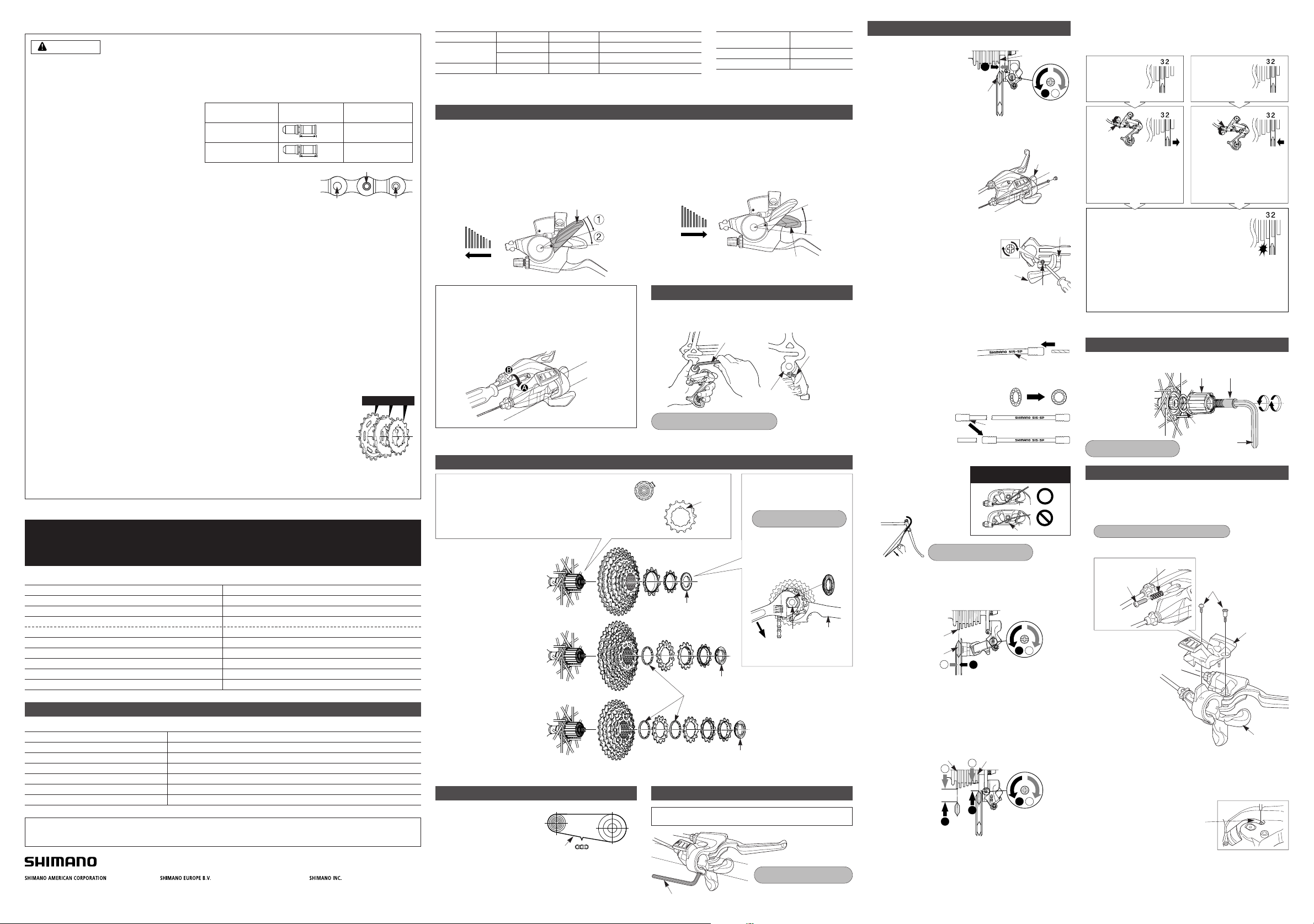
Gear shifting operation
This release lever is equipped with a 2-way release mechanism which allows release operations to be carried out by either pushing or pulling
the lever.
Both lever (A) and lever (B) always return to the initial position when they are released after shifting. When operating one of the levers,
always be sure to turn the crank arm at the same time.
To shift from a small sprocket to a larger sprocket
(Lever A)
To shift one step only, press lever (A) to the (1) position.
To shift two steps at one time, press to the (2) position.
To shift from a large sprocket to a smaller sprocket
(Lever B)
Press lever (B) once to shift one step from a larger to a smaller
sprocket.
Lever (A) initial position
Lever (B)
2-way release
SIS Adjustment
5. SIS Adjustment
Operate the shifting lever several times to move the chain to the
2nd sprocket. Then, while pressing the lever just enough to take
up the play in the lever, turn the crank arm.
When shifting to
3rd
Tighten the outer casing
adjustment barrel until the
chain returns to the 2nd
sprocket. (clockwise)
Loosen the outer casing
adjustment barrel until the
chain touches the 3rd sprocket
and makes noise. (counter
clockwise)
When no sound
at all is heard
Best setting
The best setting is when the shifting lever is
operated just enough to take up the play and the
chain touches the 3rd sprocket and makes noise.
* Return the lever to its original position (the position where
the lever is at the 2nd sprocket setting and it has been
released) and then turn the crank arm clockwise. If the
chain is touching the 3rd sprocket and making noise, turn the outer
casing adjustment barrel clockwise slightly to tighten it until the noise
stops and the chain runs smoothly.
Operate lever to change gears, and check that no noise occurs
in any of the gear positions.
For the best SIS performance, periodically lubricate all
power-transmission parts.
2. Connection and securing of the inner cable
Operate lever (B) 8 or more times
to set the lever to the highest
position, check on the indicator
that the highest position is correct,
and then install and adjust the
inner cable.
Cutting the outer casing
When cutting the outer casing, cut the opposite end to the end
with the marking. After cutting the outer
casing, make the end round so that the
inside of the hole has a uniform diameter.
Attach the same outer
end cap to the cut end of
the outer casing.
Outer end cap
1
1 2
2
Largest
sprocket
Guide pulley
Low adjustment
screw
3. Low adjustment
Turn the low adjustment screw so that the guide pulley moves to
a position directly in line with the largest sprocket.
4. How to use the B-tension adjustment screw
Mount the chain on the smallest chainring and the largest
sprocket, and turn the crank arm backward. Then turn the
B-tension adjustment screw to adjust the guide pulley as close to
the sprocket as possible but not so close that it touches. Next,
set the chain to the smallest sprocket and repeat the above to
make sure that the pulley does not touch the sprocket.
1
2
1 2
2
1
Largest sprocket Smallest sprocket
B-tension
adjustment screw
Connect the cable to the rear
derailleur and, after taking up
the initial slack in the cable,
re-secure to the rear derailleur
as shown in the illustration.
Pull
Tightening torque :
5 - 7 N·m {44 - 60 in. lbs.}
1. Top adjustment
Turn the top adjustment screw
to adjust so that the guide
pulley is in line with the outer
line of the smallest sprocket
when looking from the rear.
1
2
1 2
Outer line of
smallest sprocket
Guide pulley
Top adjustment
screw
Lever (B)
Groove
Note: Be sure that the cable is
securely in the groove.
Adjustment bolt
Adjustment bolt
General Safety Information
WARNING
Note
• If gear shifting operations do not feel smooth, wash the derailleur and lubricate all moving parts.
• If the amount of looseness in the links is so great that adjustment is not possible, you should replace the derailleur.
• You should periodically clean the derailleur and lubricate all moving parts (mechanism and pulleys).
• If gear shifting adjustment cannot be carried out, check the degree of parallelism at the rear end of the bicycle. Also check if the
cable is lubricated and if the outer casing is too long or too short.
• If you hear abnormal noise as a result of looseness in a pulley, you should replace the pulley.
• If the wheel becomes stiff and difficult to turn, you should lubricate it with grease.
• Do not apply any oil to the inside of the hub, otherwise the grease will come out.
• You should periodically wash the sprockets in a neutral detergent and then lubricate them again. In addition, cleaning the chain
with neutral detergent and lubricating it can be a effective way of extending the useful life of the sprockets and the chain.
• If the chain keeps coming off the sprockets during use, replace the sprockets and the chain.
• Use a frame with internal cable routing is strongly discouraged as it has tendencies to impair the SIS shifting function due to its
high cable resistance.
• Always be sure to use the sprocket set bearing the same group marks. Never use in combination with a
sprocket bearing a different group mark.
• Use an outer casing which still has some length to spare even when the handlebars are turned all the way
to both sides. Furthermore, check that the shifting lever does not touch the bicycle frame when the
handlebars are turned all the way.
• Grease the inner cable and the inside of the outer casing before use to ensure that they slide properly.
• For smooth operation, use the specified outer casing and the bottom bracket cable guide.
• Operation of the levers related to gear shifting should be made only when the front chainwheel is turning.
• Do not disassemble the indicator and shifting lever unit, as this may damage them or cause mis-operation.
• Parts are not guaranteed against natural wear or deterioration resulting from normal use.
• For maximum performance we highly recommend Shimano lubricants and maintenance products
• For any questions regarding methods of installation, adjustment, maintenance or operation, please contact a professional
bicycle dealer.
“Maintenance interval depends on the usage and riding circumstances. Clean regularly the chain
with an appropriate chaincleaner. Never use alkali based or acid based solvents such as rust
cleaners. If those solvent be used chain might break and cause serious injury.”
• Check that the wheels are fastened securely before riding the bicycle. If the wheels are loose in any way, they may come off the
bicycle and serious injury may result.
• Use the reinforced connecting pin only for connecting the narrow type of chain.
• There are two different types of reinforced connecting
pins available. Be sure to check the table below before
selecting which pin to use.
If connecting pins other than reinforced connecting
pins are used, or if a reinforced connecting pin or tool
which is not suitable for the type of chain is used,
sufficient connection force may not be obtained, which
could cause the chain to break or fall off.
• If it is necessary to adjust the length of the chain due
to a change in the number of sprocket teeth, make the cut at some other place than the place
where the chain has been joined using a reinforced connecting pin or an end pin. The chain will
be damaged if it is cut at a place where it has been joined with a reinforced connecting pin or
an end pin.
• Check that the tension of the chain is correct and that the chain is not damaged. If the tension is
too weak or the chain is damaged, the chain should be replaced. If this is not done, the chain may break and cause serious
injury.
• Use a front chainwheel which is compatible with 9-speed chains in conjunction with Shimano CN-HG73 and CN-HG53 chains. If
a chainwheel for an 8-speed chain or less is used, front chainwheel gear shifting problems may occur, or the chain pins might
fall out, causing the chain to break.
• Obtain and read the service instructions carefully prior to installing the parts. Loose, worn or damaged parts may cause the
bicycle to fall over and serious injury may occur as a result. We strongly recommend only using genuine Shimano replacement
parts.
• Obtain and read the service instructions carefully prior to installing the parts. If adjustments are not carried out correctly, the
chain may come off and this may cause you to fall off the bicycle which could result in serious injury.
• Read these Technical Service Instructions carefully, and keep them in a safe place for later reference.
Chain toolChain
9-speed super narrow
chain such as
CN-7701 / CN-HG93
8- / 7- / 6-speed narrow
chain such as
CN-HG50 / CN-HG40
Reinforced
connecting pin
TL-CN32 /TL-CN27
TL-CN32 /TL-CN27
6.5mm
7.1mm
Silver
Black
g
a
-
18
T
-
S
H
I
M
A
N
O
H
Y
P
E
R
G
L
I
D
E
C
a
g
-
1
5
T
a
g
-
1
3
T
Group marks
Reinforced Connecting Pin
End Pin Link Pin
SI-6TF0A-003-00
Adjusting the grip width
It is recommended that you adjust the grip widths of the levers
to the most comfortable widths for gear shifting and braking.
A
: Becomes narrower
B
: Becomes wider
4. After checking that the indicator needle is at the left edge, install
the indicator from directly above. Push the indicator downward
from above until it is aligned with the
positioning groove.
Replacement of the indicator
Disassembly and reassembly should only be carried out when
replacing the indicator.
1. Remove the stroke adjustment bolt and the two indicator stopper
screws which are securing the spring and the indicator.
2. Remove the indicator unit as shown in the illustration.
3. Operate lever (B) at least eight times to set the lever to the
highest position.
5. Check the operation of the indicator. If it does not operate
correctly, re-install the indicator while taking particular note of
steps 3. to 4.
Do not disassemble the indicator and shifting lever unit, as this may
damage them or cause mis-operation.
Tightening torque : 0.3 - 0.5 N·m {3 - 4 in. lbs.}
Indicator set screws
Lever (B)
Positioning groove
Indicator
Spring
Stroke
adjustment bolt
Install the inner hole cover by turning it
as shown in the illustration until it stops.
Do not turn it any further than this,
otherwise it may damage the screw
thread.
Feed lever
Unit cover
Inner hole cover
Installation of the rear derailleur
When installing, be careful not to let the B-tension adjustment
screw come into contact with the dropout tab, otherwise
deformation may result.
Bracket spindle Tightening torque :
8 - 10 N·m {70 - 86 in. lbs.}
5 mm Allen key
Dropout tab
B-tension
adjustment screw
Replacement of the freewheel body
After removing the hub axle, remove the freewheel body fixing bolt
(inside the freewheel body), and then replace the freewheel body.
Note:
Do not attempt to
disassemble the
freewheel body,
because it may result
in a malfunction.
Freewheel body Freewheel body fixing bolt
Freewheel body washer
10 mm Allen key
(TL-WR37)
Disassembly
Assembly
Tightening torque:
35 - 50 N·m {305 - 434 in. lbs.}
Inserting the inner cable
Insert the inner cable into the outer casing from the end with the
marking on it. Apply grease from the end with the marking in
order to maintain cable operating efficiency.
Marking
Chain
Largest chainringLargest chainring
Add 2 links (with the chain on
both the largest sprocket and
the largest chainring)
Chain length
CS-HG61
bg
9 11, 12, 13, 14, 16, 18, 21, 24, 28T
Installation of the sprockets
H
Y
P
E
R
G
L
I
D
E
-
C
J
A
P
A
N
U
.
S
.
P
A
T
4
2
6
8
2
5
9
L
O
C
K
4
0
0
k
g
/
c
m
O
N
A
M
I
H
S
ap
as
34T
ap
a
s
3
0
T
a
p
as
2
6
T
ap
as
2
3T
as
2
0
T
1
7
T
as
a
u
1
1
T
as
a
u
13T
a
s
a
u
15T
C
S
-
6
J
P
A
A
N
M
9
0
H
P
Y
E
E
R
G
L
I
D
1
1
T
1
6T
14T
9S
9S
9S
13T
12T
a
Q
a
r
ba
11T
a
Q
a
r
ba
C
S
-
6
J
P
A
A
N
M
9
0
H
P
Y
E
E
R
G
L
I
D
1
1
T
1
4
T
CS-HG50-9 / CS-HG30-9 (ar)
CS-HG50-9 / CS-HG30-9 (au)
CS-HG61 (bg)
Lock ring
Lock ring
Sprocket spacers
Lock ring
For each sprocket, the surface that has the group mark
should face outward and be positioned so that the wider
part of each sprocket and the A part (where the groove
width is wide) of the freewheel body are aligned.
The groove is wide at
one place only.
a
c
-
1
4
T
A
Wide part
• For installation of the sprockets,
use the special tool (TL-LR15 /
LR10) to tighten the lock ring.
• To replace the sprockets, use
the special tool (TL-LR15 /
LR10) and TL-SR21 to remove
the lock ring.
Tightening torque:
30 - 50 N·m {261 - 434 in. lbs.}
Lock ring
Tool
(TL-SR21)
Disassembly
TL-LR15/LR10
 Loading...