

Shimano Steps BT-E6000, Steps BT-E6010, Steps BT-E8014, Steps BT-E8010, Steps BT-E8020 User Manual
...Page 1

UM-78N0A-000-00
User's manual
Original instructions
E6100 Series
Shimano Total Electric Power System
Page 2

Page 3

1
CONTENTS
IMPORTANT NOTICE
......................................................................................3
Important safety information
.........................................................................3
To ensure safety
...........................................................................................3
Features of SHIMANO STEPS
..........................................................................7
Assist mode .................................................................................................................................7
Start your STEPS
........................................................................................... 8
Names of parts
...........................................................................................11
Specifications
.............................................................................................12
Preparation
...............................................................................................13
Charging the battery ................................................................................................................13
Charger LED lamp .....................................................................................................................17
Battery LED lamp ......................................................................................................................17
Handling the battery ................................................................................................................18
Installing and removing the battery ........................................................................................19
Installing and removing the cycle computer ...........................................................................24
Operation
.................................................................................................25
Turning the power ON / OFF ....................................................................................................25
Basic operation .........................................................................................................................27
Turning the light ON / OFF .......................................................................................................29
Basic status display ....................................................................................................................30
Changing the assist mode ........................................................................................................32
Walk assist mode ......................................................................................................................33
Switching the travel data display (SC-E6100) ..........................................................................34
Switch the gear shifting mode .................................................................................................35
Setting menu (SC-E6100)
.............................................................................36
Launching ..................................................................................................................................36
Clear ...........................................................................................................................................37
Clock ..........................................................................................................................................38
Start mode .................................................................................................................................39
Backlight ....................................................................................................................................40
English
Page 4

2
Brightness ..................................................................................................................................41
Beep ...........................................................................................................................................42
Unit ............................................................................................................................................43
Language ...................................................................................................................................44
Font color ..................................................................................................................................45
Adjust ........................................................................................................................................45
Shift timing ...............................................................................................................................46
Shifting advice ..........................................................................................................................47
RD protection reset ...................................................................................................................48
Exit .............................................................................................................................................48
Settings (EW-EN100)
...................................................................................49
RD protection reset ...................................................................................................................49
Adjust ........................................................................................................................................49
Drive unit setting data backup function
......................................................... 49
Connection and communication with devices
..................................................50
About wireless functions ..........................................................................................................50
Errors and remedies
....................................................................................51
Battery LED lamp error indications ..........................................................................................51
Error messages on the cycle computer ....................................................................................52
Error indications (EW-EN100) ...................................................................................................54
Troubleshooting ........................................................................................................................55
Page 5
3
User's manuals in other languages are
available at :
http://si.shimano.com
IMPORTANT NOTICE
•
Contact the place of purchase or a bicycle dealer for
information on installation and adjustment of the
products which are not found in the user's manual. A
dealer's manual for professional and experienced bicycle
mechanics is available on our website (http://si.shimano.
com).
•
Do not disassemble or alter this product.
•
Use the product according to local laws and regulations.
•
The Bluetooth® word mark and logos are registered
trademarks owned by Bluetooth SIG, Inc. and any use of
such marks by SHIMANO INC. is under license. Other
trademarks and trade names are those of their respective
owners.
For safety, be sure to read this user's
manual thoroughly before use, and
follow them for correct use.
Important safety information
For replacement information, contact the place of purchase
or a bicycle dealer.
Be sure to observe the following in order to avoid burns or
other injury from fluid leakages, overheating, fire or
explosions.
To ensure safety
DANGER
Handling the battery
•
Do not deform, modify, disassemble or apply solder
directly to the battery. Doing so may cause leakage,
overheating, bursting, or ignition of the battery.
•
Do not leave the battery near sources of heat such as
heaters. Do not heat the battery or throw it into a fire.
Doing so may cause bursting or ignition of the battery.
•
Do not subject the battery to strong shocks or throw it. If
this is not observed, overheating, bursting, or fire may
occur.
•
Do not place the battery into fresh water or sea water,
and do not allow the battery terminals to get wet. Doing
so may cause overheating, bursting, or ignition of the
battery.
•
Use the SHIMANO specified charger and observe the
specified charging conditions when charging the
specified battery. Not doing so may cause overheating,
bursting, or ignition of the battery.
Page 6

4
WARNING
To ensure safe riding
•
Do not give too much of your attention to the cycle
computer display while riding, otherwise accidents may
result.
•
Check that the wheels are securely installed to the bicycle
before commencing riding. If the wheels are not securely
installed, the bicycle may fall over and serious injury may
result.
•
If riding a power-assisted bicycle, make sure that you are
fully familiar with the starting-off characteristics of the
bicycle before riding it on roads with several vehicle lanes
and pedestrian footpaths. If the bicycle starts off
suddenly, accidents may result.
•
Check that the bicycle lights illuminate before riding at
night.
Using the product safely
•
Be sure to remove the battery and charging cable before
wiring or attaching parts to the bicycle. Otherwise, an
electric shock may result.
•
When charging the battery while it is installed on the
bicycle, do not move the bicycle. The power plug for the
battery charger may come loose and not be fully inserted
into the electrical outlet, resulting in risk of fire.
•
When installing this product, be sure to follow the
instructions given in the user's manual. Furthermore, it is
recommended that you use only genuine Shimano parts
at these times. If bolts and nuts are left loosened or the
product is damaged, the bicycle may suddenly fall over
and serious injury may result.
•
Do not disassemble the product. Disassembling it may
cause injury to persons.
•
After reading the user's manual carefully, keep it in a
safe place for later reference.
Handling the battery
•
If any liquid leaking from the battery gets into your eyes,
immediately wash the affected area thoroughly with
clean water such as tap water without rubbing your eyes,
and seek medical advice immediately. If this is not done,
the battery liquid may damage your eyes.
•
Do not recharge the battery in places with high humidity
or outdoors. Doing so may result in electric shock.
•
Do not insert or remove the plug while it is wet. If this is
not observed, electric shocks may result. If there is water
leaking out of the plug, dry it thoroughly before
inserting it.
•
If the charging of the battery continues exceeds 2 hours
after the prescribed charging time, immediately unplug
the battery from the outlet to stop charging, and contact
the place of purchase. Failure to do so may cause
overheating, bursting, or ignition of the battery.
•
Do not use the battery if it has any noticeable scratches
or other external damage. Doing so may cause bursting,
overheating or problems with operation.
•
The operating temperature ranges for the battery are
given below. Do not use the battery in temperatures
outside these ranges. If the battery is used or stored in
temperatures outside these ranges, fire, injury or
problems with operation may occur.
1. During discharge: –10 °C - 50 °C
2. During charging: 0 °C - 40 °C
Cleaning
•
The frequency of maintenance will vary depending on
the riding conditions. Periodically clean the chain using
an appropriate chain cleaner. Do not use alkaline or
acidic cleaning agents for removing rust under any
circumstances. If such cleaning agents are used, they may
damage the chain and serious injury may result.
Page 7
5
CAUTION
To ensure safe riding
•
Observe the instructions in the user's manual for the
bicycle, in order to ride safely.
Using the product safely
•
Periodically check the battery charger and adapter,
particularly the cord, plug, and case, for any damage. If
the charger or adapter is broken, do not use it until it has
been repaired.
•
This appliance is not intended for use by persons
(including children) with reduced physical, sensory or
mental capabilities, or lack of experience and knowledge,
unless they have been given supervision or instruction
concerning use of the appliance by a person responsible
for their safety.
•
Do not allow children to play near the product.
Handling the battery
•
Do not leave the battery in a place exposed to direct
sunlight, inside a vehicle on a hot day, or other hot
places. This may result in battery leakage.
•
If any leaked fluid gets on your skin or clothes, wash it
off immediately with clean water. The leaked fluid may
damage your skin.
•
Store the battery in a safe place out of the reach of
infants and pets.
Cleaning
•
If any malfunctions or other problems occur, contact the
place of purchase.
•
Never attempt to modify the system yourself, as it may
cause problems with system operation.
Note
Using the product safely
•
Be sure to install caps to any connectors which are not
being used.
•
For installation and adjustment of the product, consult a
dealer.
•
The Product is designed to be fully waterproof to
withstand wet weather riding conditions. However, do
not deliberately place them into water.
•
Do not clean the bicycle in a high-pressure wash. If water
gets into any of the components, operating problems or
rusting may result.
•
Do not turn the bicycle upside down. The cycle computer
or the shifting switch may get damaged.
•
Handle the product carefully, and avoid subjecting it to
any strong shocks.
•
Although the bicycle still functions as a normal bicycle
even when the battery is removed, the light does not
turn on if it is connected to the electric power system. Be
aware that using the bicycle under these conditions will
be considered non-observance of the road traffic laws in
Germany.
•
When charging the battery while it is mounted on the
bicycle, be careful of the following:
-
When charging, make sure there is no water on the
charging port or the charger plug.
-
Ensure that the battery is locked into the battery
mount before charging.
-
Do not remove the battery from the battery mount
while charging.
-
Do not ride with the charger mounted.
-
Close the charging port cap when not charging.
-
Stabilize the bicycle to ensure that it does not
collapse during charging.
Handling the battery
•
When you carry a power-assisted bicycle in a car, remove
the battery from the bicycle and place the bicycle on a
stable surface in the car.
•
Before connecting the battery, make sure that there is no
buildup of water or dirt in the connector where the
battery will be connected.
•
The use of a genuine Shimano battery is recommended. If
using a battery from another manufacturer, make sure to
carefully read the instruction manual for the battery
before use.
Disposal information for countries outside
the European Union
This symbol is only valid within the
European Union. Follow local regulations
when disposing of used batteries. If you
are not sure, consult the place of purchase
or a bicycle dealer.
Page 8

6
Connection and communication with PCs
A PC linkage device can be used to connect a PC to the
bicycle (system or components), and E-TUBE PROJECT can be
used to carry out tasks such as customizing single
components or the whole system and updating firmware.
•
PC linkage device: SM-PCE1
•
E-TUBE PROJECT: PC application
•
Firmware: software inside each component
Connection and communication with
smartphones and tablets
It is possible to customize single components or the system,
and update firmware, using E-TUBE PROJECT for
smartphones/tablets after connecting the bicycle (system or
components) to a smartphone or tablet via Bluetooth
®
LE.
•
E-TUBE PROJECT: app for smartphones/tablets
•
Firmware: software inside each component
Cleaning
•
The number found on the battery mount key is necessary
when purchasing spare keys. Keep it in a safe place.
There is a space to enter the key number on the back
cover of this user's manual. Enter the key number for
safekeeping and later reference.
•
Contact the place of purchase for updates of the product
software. The most up-to-date information is available
on the Shimano website. For details, refer to the
"Connection and communication with the PC" section.
•
Do not use thinner or other solvents to clean any of the
products. As such substances may damage the surfaces.
•
You should periodically wash the chainrings in a neutral
detergent. In addition, cleaning the chain with neutral
detergent and lubricating it can be an effective way of
extending the useful life of the chainrings and the chain.
•
Use a damp cloth, with the water well wrung out, when
cleaning the battery and plastic cover.
•
For any questions regarding handling and maintenance,
contact the place of purchase.
•
Products are not guaranteed against natural wear and
deterioration from normal use and aging.
•
For maximum performance we highly recommend
Shimano lubricants and maintenance products.
Assist
•
If the settings are not correct, for instance if the chain
tension is too tight, the proper assist force may not be
obtained. If this happens, contact the place of purchase.
<DU-E6110>
•
This component is compatible with coaster brakes. If the
crank is not installed in the correct position or the chain
tension has not been correctly adjusted, contact the place of
purchase, as there may not be proper assistance power.
Label
•
Some of the important information contained in this user's
manual is also indicated on the battery charger label.
FCC compliance information
This device complies with Part 15 of the FCC Rules.
Operation is subject to the following two conditions:
(1) This device may not cause harmful interference, and
(2) This device must accept any interference received,
including interference that may cause undesired
operation.
NOTE: This equipment has been tested and found to
comply with the limits for a Class B digital device,
pursuant to Part 15 of the FCC Rules. These limits are
designed to provide reasonable protection against
harmful interference in a residential installation. This
equipment generates, uses and can radiate radio
frequency energy and, if not installed and used in
accordance with the instructions, may cause harmful
interference to radio communications. However, there
is no guarantee that interference will not occur in a
particular installation. If this equipment does cause
harmful interference to radio or television reception,
which can be determined by turning the equipment off
and on, the user is encouraged to try to correct the
interference by one or more of the following measures:
-
Reorient or relocate the receiving antenna.
-
Increase the separation between the equipment and
receiver.
-
Connect the equipment into an outlet on a circuit
different from that to which the receiver is
connected.
-
Consult the dealer or an experienced radio/TV
technician for help.
Page 9
7
Features of SHIMANO STEPS
•
Lightweight, compact design
•
Silent, smooth ride
•
High shifting performance system (In the case of electronic gear shifting)
This system uses accurate sensors to enable shifting gears by providing the most appropriate level of power assistance
carefully adjusted by computer controls.
•
Full Automatic Shifting (In the case of electronic 8/5-speed gear shifting)
The sensors detect riding conditions, whether you are riding up a hill against the wind, or on flat ground with no wind;
the automatic gear shifting system uses computer controls to make your ride more pleasant.
•
Start mode (In the case of electronic gear shifting)
This function allows automatic shifting down to a preset gear when you stop the bicycle such as at traffic lights so that
you can start traveling at a light gear.
*
If, while the bicycle is stopped, you shift to a gear lower than the set gear, the system will not automatically shift up.
•
Coaster brake compatible (DU-E6110)
Smoothly provides sufficient control power.
•
Light off road
Sporty, provides powerful assistance. Can only be used when set by the manufacturer of the completed bicycle.
•
Walk assistance function (Walk assist mode)
*
The Walk assist mode function may not available in certain regions.
*
Some of the functions listed above can only be used once the firmware has been updated. If this is the case, consult the
place of purchase, and carry out the firmware updates.
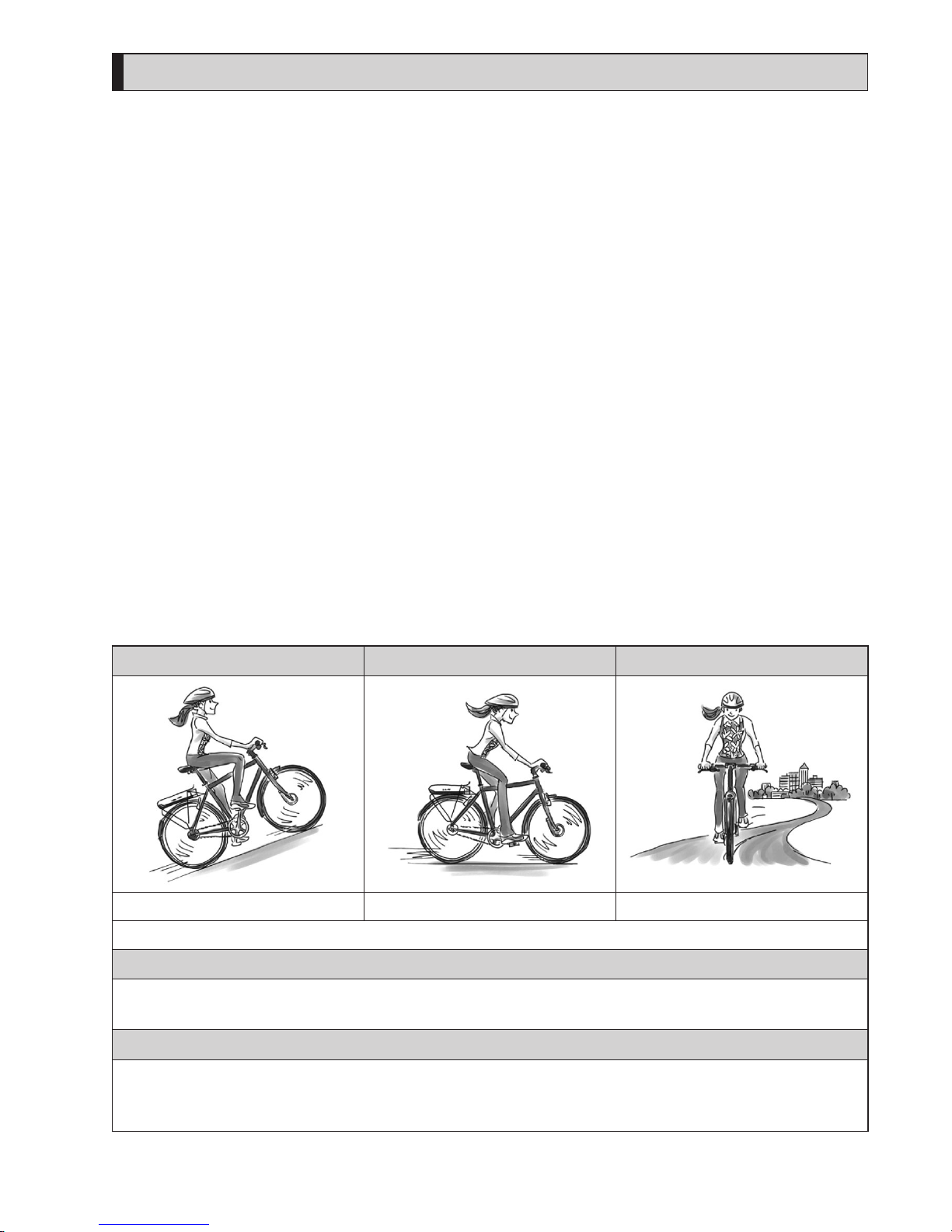
Assist mode
You can select a SHIMANO STEPS assist mode for each particular application.
[HIGH] [NORM] (Normal) [ECO]
Steep uphill slopes. Gentle slope or level ground. Long distance riding on level ground.
When the battery level is running low, the level of assistance is lowered to increase the traveling range.
[OFF]
•
When you don't need power assistance
•
When you are concerned about remaining battery power
[WALK]
•
When you walk while pushing the E-BIKE loaded with heavy baggage
•
When walking the E-BIKE out of an underground bicycle parking garage
*
This mode may not be available in certain regions
Page 10
8
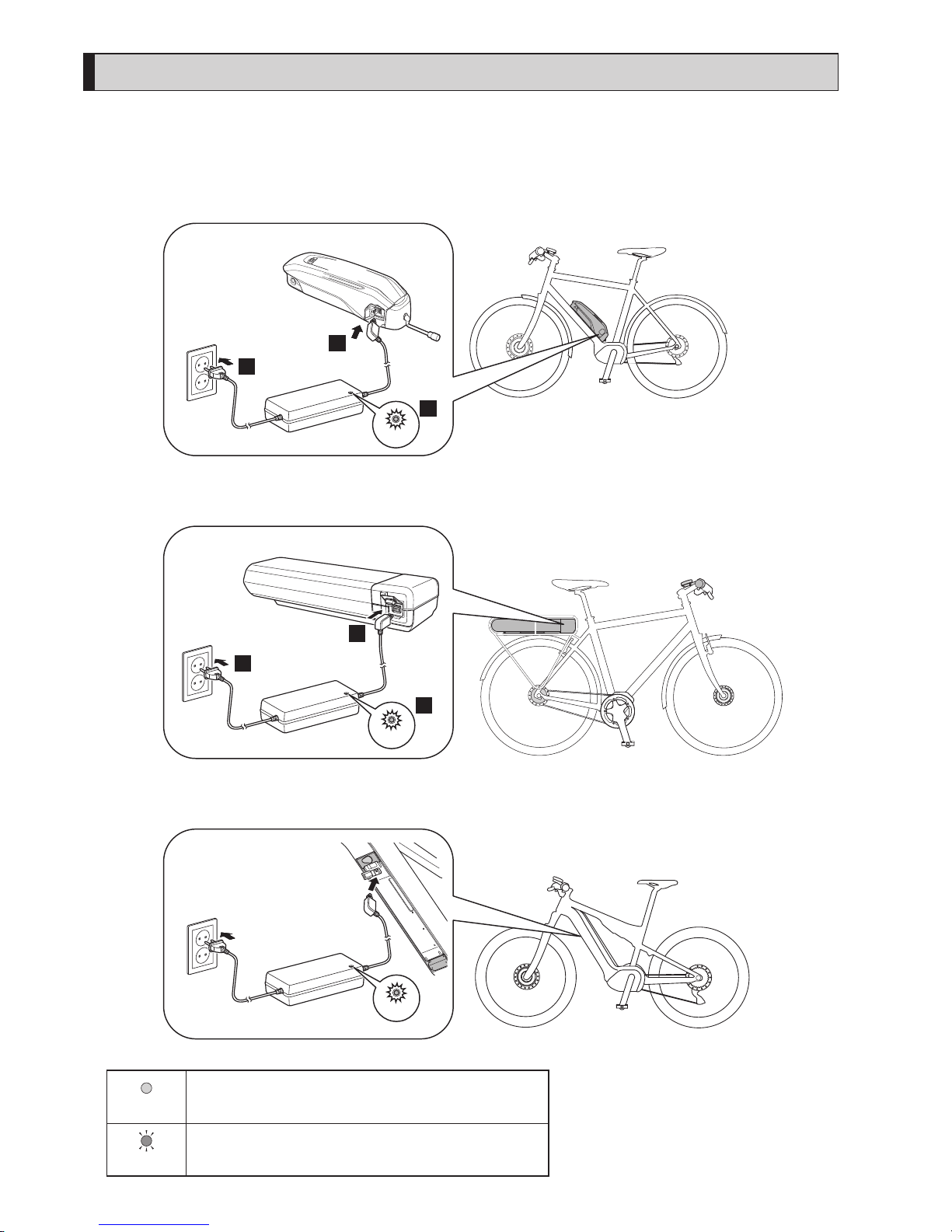
Start your STEPS
1.
Charge the battery.
It is possible to charge the battety even while it is mounted on the bicycle.
For detals, see “Charging the battery while installed on the bicycle.”
<Down-tube mount type battery>
3
2
1
Light On
Example : BT-E8010
<Rear carrier mount type battery>
1
3
2
Light On
BT-E6000 / BT-E6001
<Integrated battery>
Light On
BT-E8020
Lights up
Charging
(Within 1 hour after the completion of charging)
Flashing
Charging error
Page 11
9
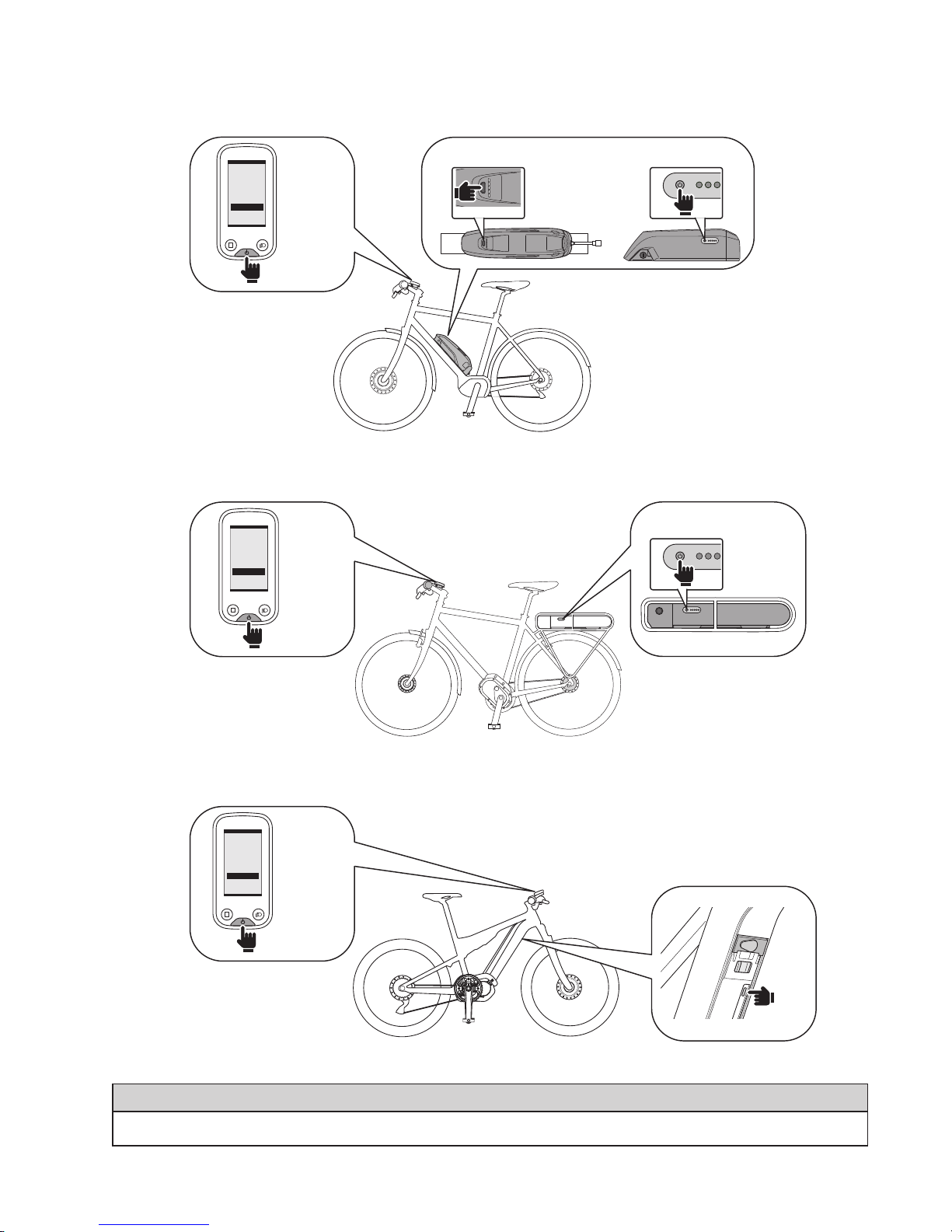
2.
Turn on the power.
To turn off the power, repeat this procedure.
<Down-tube mount type battery>
BT-E8010 / BT-E8014 BT-E6010
Long press
Or
<Rear carrier mount type battery>
Long press
BT-E6000 / BT-E6001
<Integrated battery>
Long press
NOTE
When turning the power ON/OFF, do not place your foot on the pedal.
Page 12
10
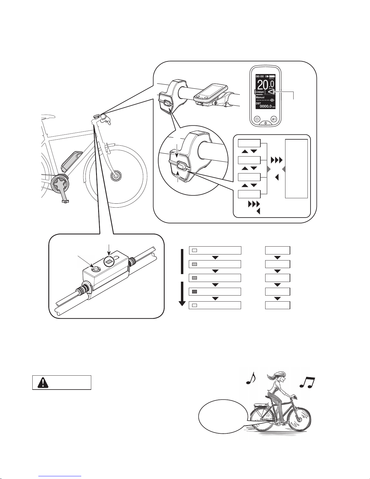
3.
Select your preferred assist mode.
The bicycle is equipped with either SC-E6100 or EW-EN100.
*
When the power is turned on, assist mode is set to [OFF].
*
To change to the [WALK] assist mode, it is
necessary to use the above assist switch.
Assist mode
display
LED lamp (inner side)
Z
< SC-E6100 >
< EW-EN100 >
X
Y
OFF
Lit in light blue
Lit in green
Lit in yellow
OFF
[OFF]
[ECO]
[NORM]
[HIGH]
[OFF]
LED lamp (inner side) indications Assist mode
Z
[HIGH]
[NORM]
[ECO]
[OFF]
[WALK]
XY
Long press Y
Short press X
4.
Ride the bicycle.
Assist will start when you start pedaling.
CAUTION
SHIMANO STEPS supports various brake systems.
Before riding, please check the brake system of your bicycle and
how to operate it beforehand.
5.
Turn off the power.
Assist
Start
Page 13
11
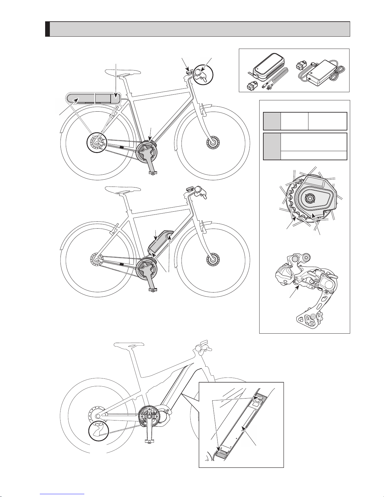
Names of parts
B
(F)
(A)
(G)
(E)
(B)
(C) (D)
(L)
*
1
*
2
< For electronic gear shifting >
(A)
Shifting
switch
•
SW-E6010
(B)
Motor unit + Internal
geared hub
Rear Derailleur (DI2)
Motor unit
Internal geared
hub
Rear Derailleur
(DI2)
(H)
(I)
(B)
(J)
(K)
Page 14

12
(C)
Cycle computer / Junction [A]
•
SC-E6100
•
EW-EN100
(H)
Battery (down-tube mount type)
•
BT-E6010
•
BT-E8010
*3
•
BT-E8014
(D)
Assist switch
•
SW-E6010
(I)
Battery mount
(down-tube mount type)
•
BM-E6010
•
BM-E8010
(E)
Drive unit
•
DU-E6100
•
DU-E6110
(J)
Battery (Integrated type)
•
BT-E8020
(F)
Battery (rear carrier mount type)
•
BT-E6000
•
BT-E6001
*3
(K)
Battery mount (Integrated type) •BM-E8020
(G)
Battery mount (rear carrier mount
type)
•
BM-E6000
(L)
Battery charger
*
1: EC-E6002 + SM-BCC1
*
2: EC-E6000
*3 If the firmware version of the drive unit is 3.2.6 or lower, the battery may not operate properly. Update the firmware
version via E-TUBE PROJECT.
Specifications
Operating temperature
range: During discharge
-10 – 50˚C Battery type Lithium ion battery
Operating temperature
range: During charging
0 – 40˚C Nominal capacity
Refer to the user's manual
for the battery. For the
latest information on
manuals, see the website
(http://si.shimano.com).
Storage temperature -20 – 70˚C Rated voltage 36 V DC
Storage temperatur
e
(Battery)
-20 – 60˚C Drive unit type Midship
Charging voltage 100 – 240 V AC Motor type Brush-less DC
Charging time
Refer to the user's manual
for the battery. For the
latest information on
manuals, see the website
(http://si.shimano.com).
Rated drive unit power 250 W
*
The maximum speed for which power assistance is provided is set by the manufacturer and is conditional on where the
bicycle is to be used.
Page 15
13
Preparation
You cannot use the battery immediately after shipment.
The battery can be used after charging it with the designated charger.
Be sure to charge it before use. The battery can be used when the LED on it lights up.
The use of a genuine SHIMANO battery is recommended. If using a battery from another manufacturer, make sure to
carefully read the instruction manual for the battery before use.
Charging the battery
Charging time varies depending on the remaining capacity of the battery and the charger used. For the designated charging
time, refer to the charger user manual.
DANGER
•
Use the battery and charger combination specified by the company for charging and follow the charging conditions specified by the
company. Not doing so may cause overheating, bursting, or ignition of the battery.
CAUTION
•
When charging the battery while it is mounted on the bicycle, be careful not to trip over the charger cord or get anything caught
on it. This may lead to injury or cause the bicycle to fall over, damaging the components.
NOTE
• When removing the battery charger power plug from the outlet or the charging
plug from the battery, do not pull it out by the cord, or it causes breakage.
• If the bicycle is stored for an extended period of time immediately after purchase,
you will need to charge the battery before using the bicycle. Once the battery is
charged, it starts to deteriorate.
• Connect to E-TUBE PROJECT and click [Connection check] to confirm whether the
battery in use is a genuine SHIMANO battery or another brand.
• Charge the batteries on a flat surface indoors.
Page 16
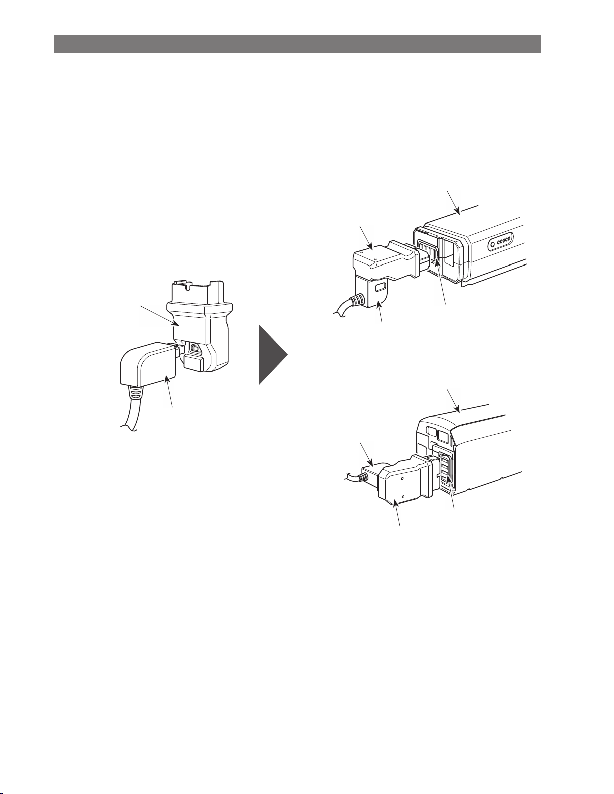
14
Charging the battery that removed from the bicycle
BT-E6000/BT-E6001/BT-E6010
Adapter (SM-BTE60) is necessary to charge BT-E6000/BT-E6001/BT-E6010 when removed from the bicycle.
1.
Attach the adapter to the charging plug.
2.
Connect the charger’s power plug to the outlet.
3.
Connect the adapter to the battery’s charging port.
Battery
Battery
Charging port
Charging port
Adapter SM-BTE60
<sold separetely>
Charging
plug
Adapter SM-BTE60
<sold separetely>
Charging
plug
Charging
plug
Adapter SM-BTE60
<sold separetely>
< BT-E6000/BT-E6001 >
< BT-E6010 >
Page 17
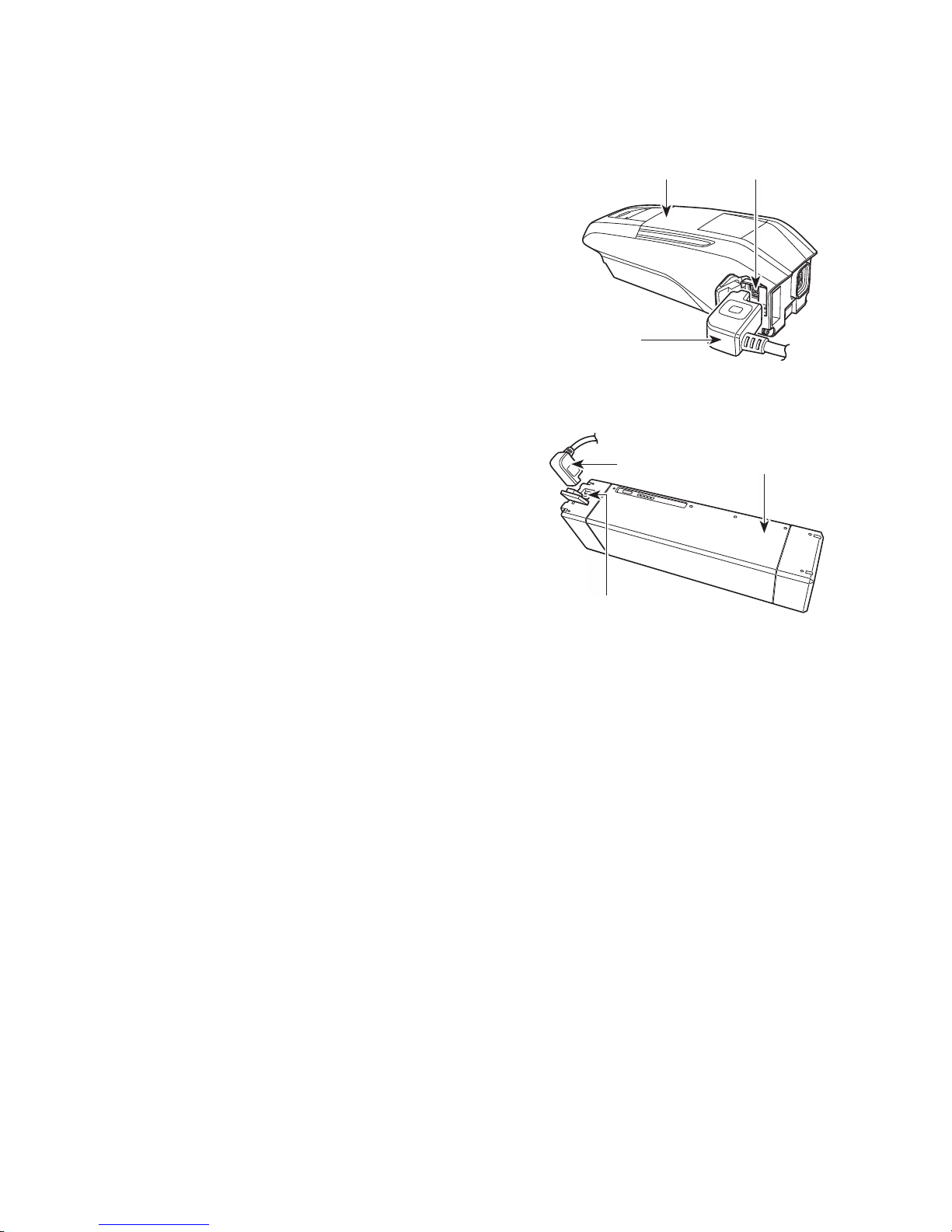
15
BT-E8010/BT-E8014/BT-E8020
1.
Connect the battery charger’s power plug to the outlet.
2.
Connect the charging plug into the battery's charging
port.
< BT-E8010/BT-E8014 >
Charging plug
Battery Charging port
< BT-E8020 >
Charging plug
Battery
Charging port
Page 18
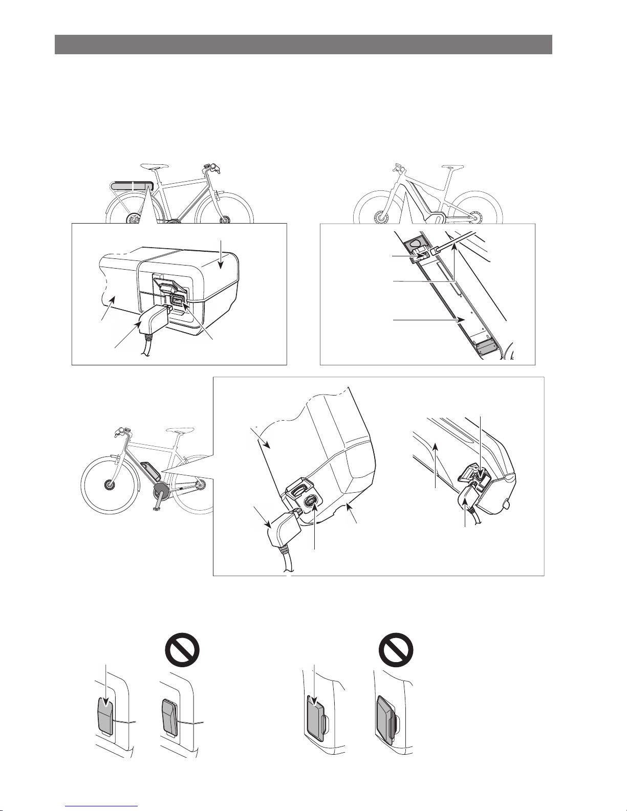
16
Charging the battery while installed on the bicycle
•
Place the battery charger on a stable surface such as the floor before charging.
•
Stabilize the bicycle to ensure that it does not collapse during charging.
1.
Connect the battery charger power plug to the outlet.
2.
Connect the charging plug to the charging port on the battery mount or the battery.
<BT-E6000/BT-E6001>
Battery mount
Charging port
Charging plug
Battery
<BT-E8020>
Battery
Charging plug
Charging port
<BT-E6010/BT-E8010/BT-E8014>
Battery
Charging
plug
Battery
mount
Charging port
<BT-E6010> <BT-E8010/BT-E8014>
Battery
Charging port
Charging plug
3.
After charging, close the charging port cap securely.
<BM-E6000>
Charging port cap
<BM-E6010>
Charging port cap
Page 19
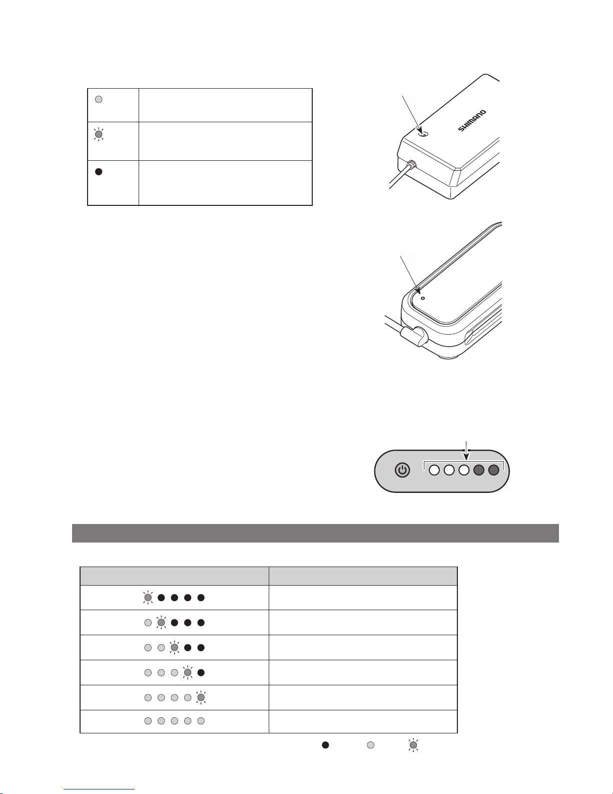
17
Charger LED lamp
After charging has started, the LED lamp on the charger
will light up.
Lit up
Charging
Blinking
Charging error
Turned
off
Battery disconnected
<EC-E6000>
Charger LED lamp
Charger LED lamp
<EC-E6002>
Battery LED lamp
Use this to check the current charging status.
The shape of the battery LED lamp varies depending on the
model number.
Battery LED lamps
Charging-in-progress indication
While battery is charging, the LED lamps on the battery light up.
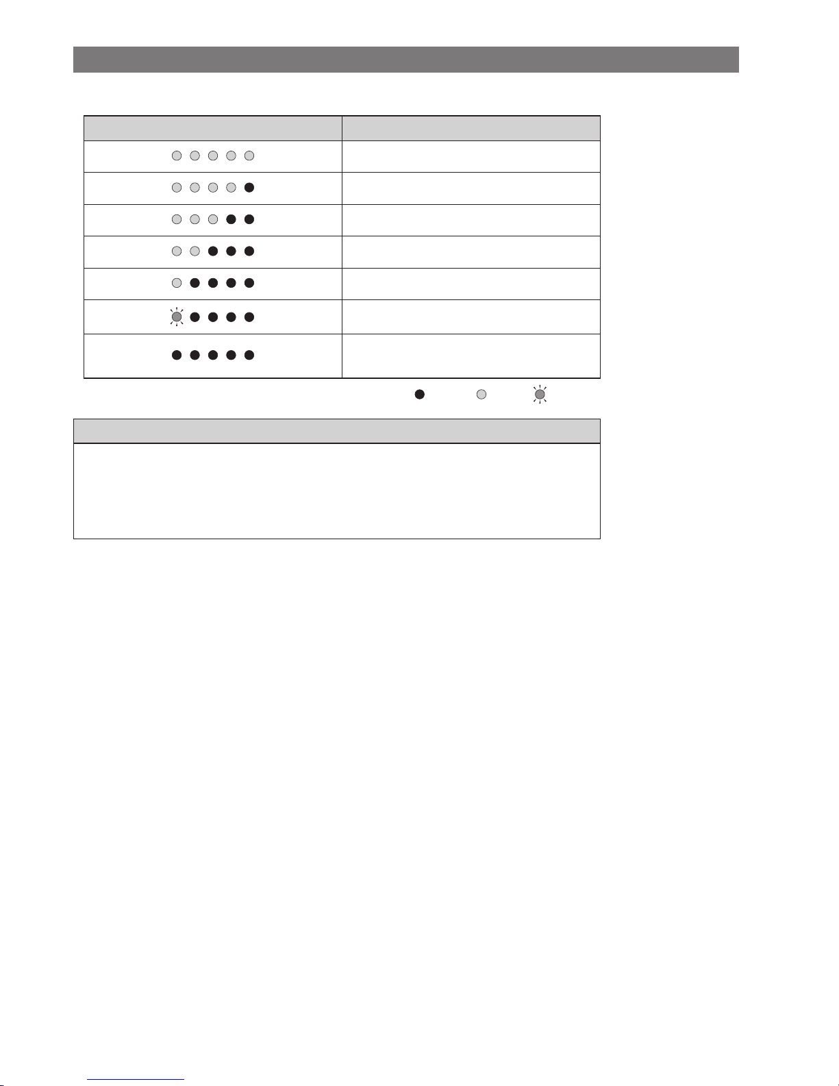
LED lamp indication*1 Battery level
0% - 20%
21% - 40%
41% - 60%
61% - 80%
81% - 99%
100%
*1
: Not lit : Lit up : Blinking
Page 20
18
Battery level indication
The current battery level can be checked by pressing the battery's power button.
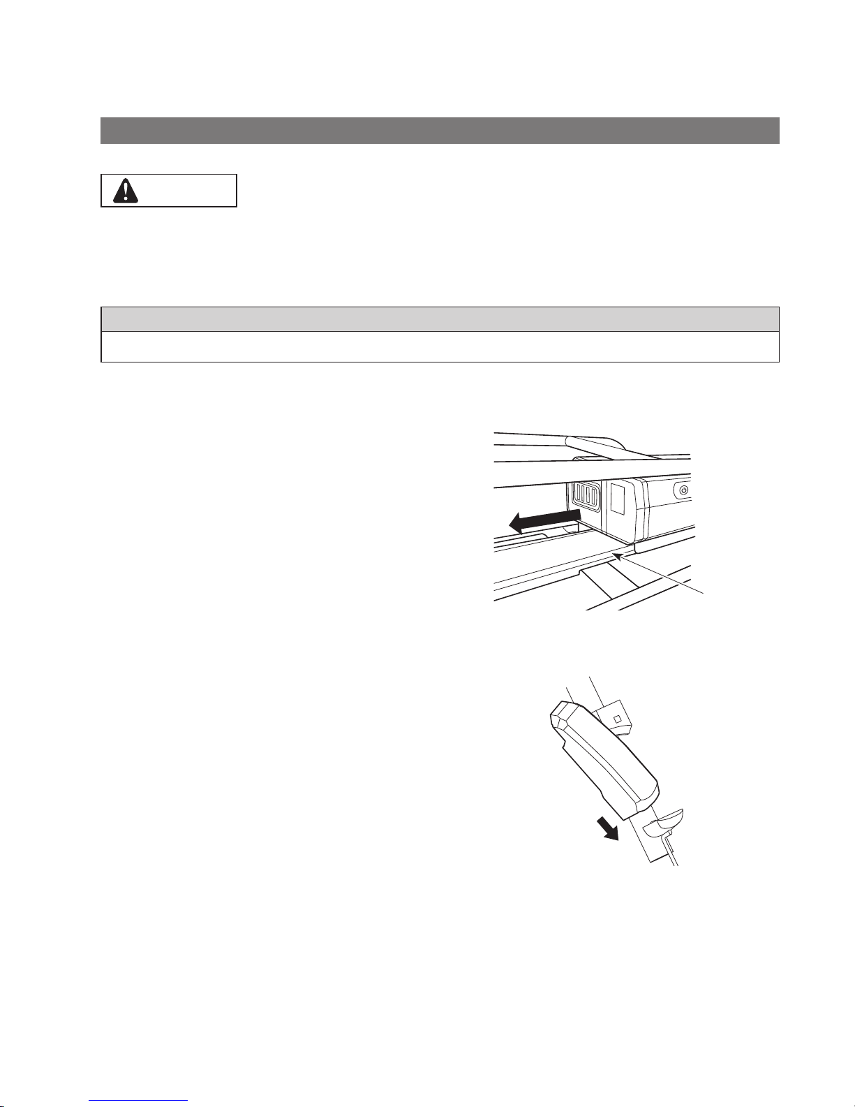
LED lamp indication*1 Battery level
100% - 81%
80% - 61%
60% - 41%
40% - 21%
20% - 1%
0% (When battery is not installed on bicycle)
0% (When battery is installed on bicycle)
Power off / Shutdown
*1
: Not lit : Lit up : Blinking
NOTE
When remaining battery capacity is low, system functions begin to shut off in the following order.
1. Power assistance (Assist mode automatically switches to [ECO] and then assistance shuts off. The switch to
[ECO] occurs earlier if a battery-powered light is connected.)
2. Gear shifting
3. Light
Handling the battery
Charging can be carried out at any time regardless of the amount of charge remaining, but you should fully charge the
battery at the following times. Be sure to use the special charger when recharging the battery at these times.
•
The battery is not fully charged at the time of purchase. Before riding, be sure to charge the battery until it is fully
charged.
If the battery has become fully spent, charge it as soon as possible. If you leave the battery without charging it, it will
cause the battery to deteriorate.
•
If the bicycle will not be ridden for a long period of time, store it away with approximately 70% battery capacity
remaining. In addition, take care not to let the battery become completely empty by charging it every 6 months.
Page 21
19
Installing and removing the battery
The battery is secured to the battery mount with the key.
The following description may not be applicable, as different types of keys are available.
Installing
CAUTION
•
Hold the battery firmly and be careful to prevent dropping when installing.
•
Pay attention to the following to prevent the battery from falling while riding the bicycle:
-
Make sure the battery is locked securely on the battery mount.
-
Do not ride the bicycle with the key inserted.
NOTE
Before riding, make sure that the charging port cap is closed.
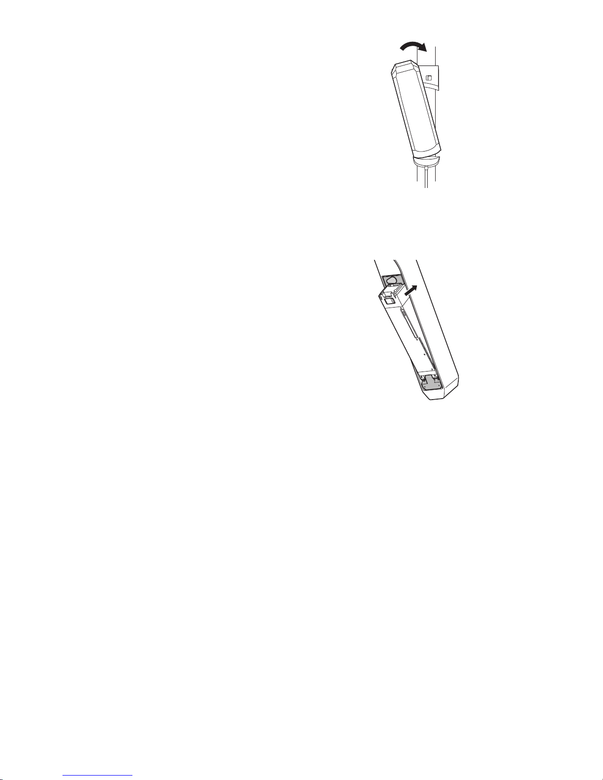
BT-E6000/BT-E6001
1.
Insert the battery in the battery mount rail from
behind.
•
Slide the battery forward, and then push it in firmly.
2.
Remove the key.
•
Return the key to the locked position and then
remove the key.
Rail
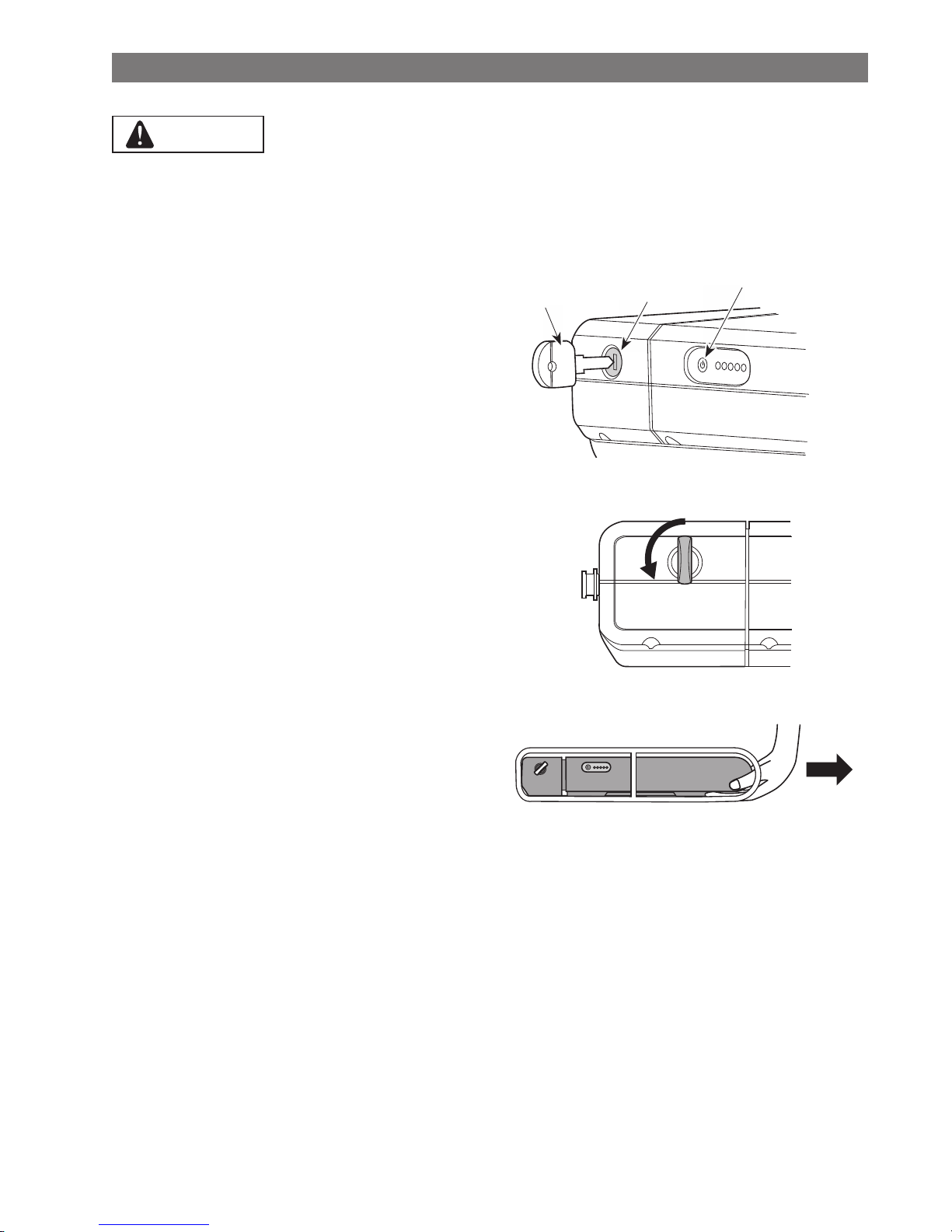
BT-E6010/BT-E8010/BT-E8014
1.
Insert the battery from bottom side.
•
Align the indentation in the bottom of the battery
with the protrusion on the battery mount.
Page 22
20
2.
Slide the battery.
•
Push in the battery until there is a click.
3.
Remove the key.
•
Return the key to the locked position and then
remove the key.
BT-E8020
This procedure is an example using a frame whose battery is removed/installed from below.
1.
Insert the battery from bottom side.
2.
Slide the battery.
•
Push in the battery until there is a click.
Page 23
21
Removing
CAUTION
•
Hold the battery firmly and be careful to prevent dropping when removing or carrying it.
BT-E6000/BT-E6001
The position of the key does not affect the insertion of the battery. You can insert it regardless of the key position.
1.
Insert the Key.
Turn off the power, then insert the key into the key
cylinder in the battery mount.
Key
Key cylinder
Push power button to
turn off the power.
2.
Turn the key until you feel some resistance.
3.
Remove the battery carefully.
You can remove the battery only when the key is in
the unlocked position.
Page 24
22
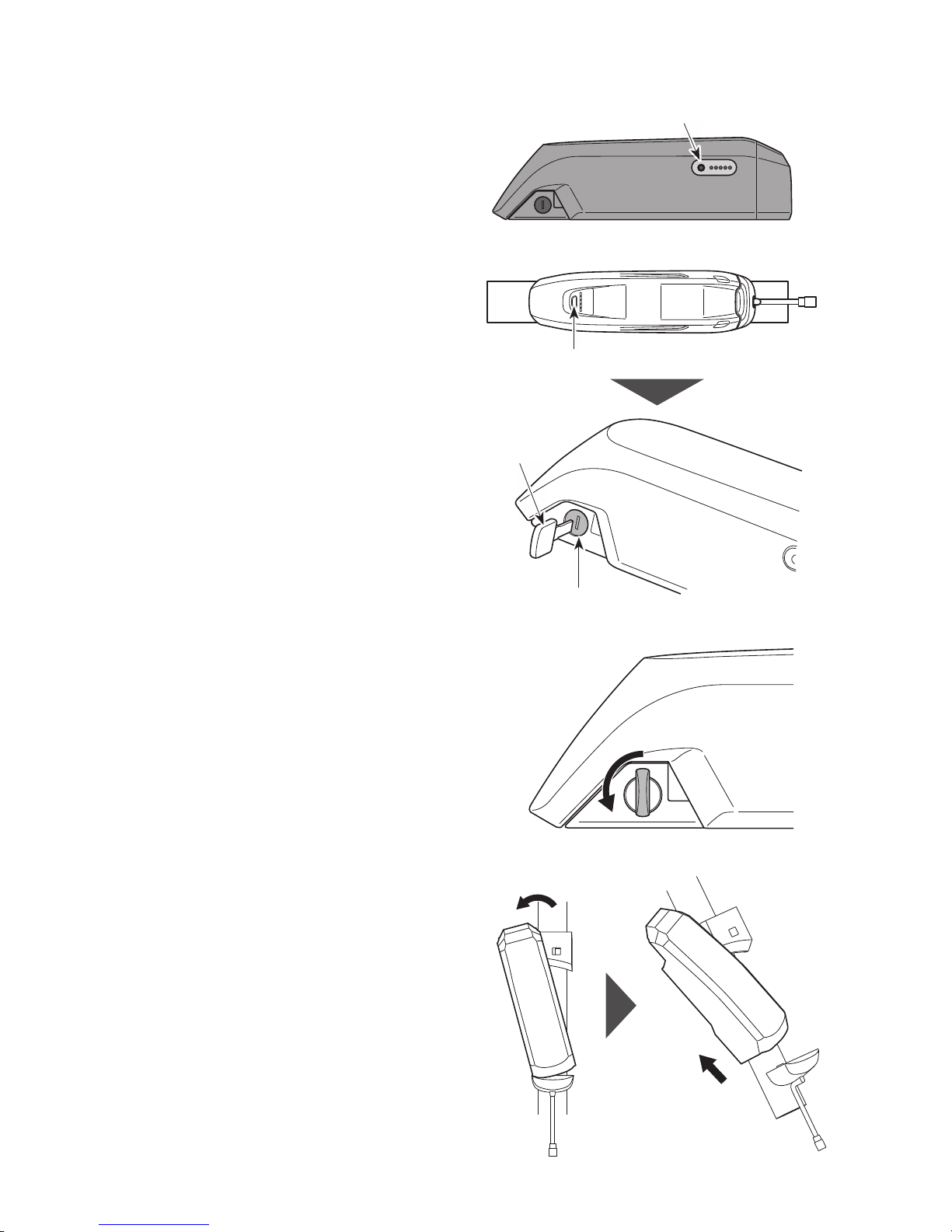
BT-E6010/BT-E8010/BT-E8014
1.
Insert the Key.
Turn off the power, then insert the key into the key
cylinder in the battery mount.
<BT-E6010>
Push power button to turn off the power.
<BT-E8010/BT-E8014>
Push power button to turn off the power.
Key
Key cylinder
2.
Turn the key until you feel some resistance.
3.
Remove the battery
•
Slide the battery, then remove it carefully.
•
You can remove the battery only when the key is in
the unlocked position.
Page 25
23
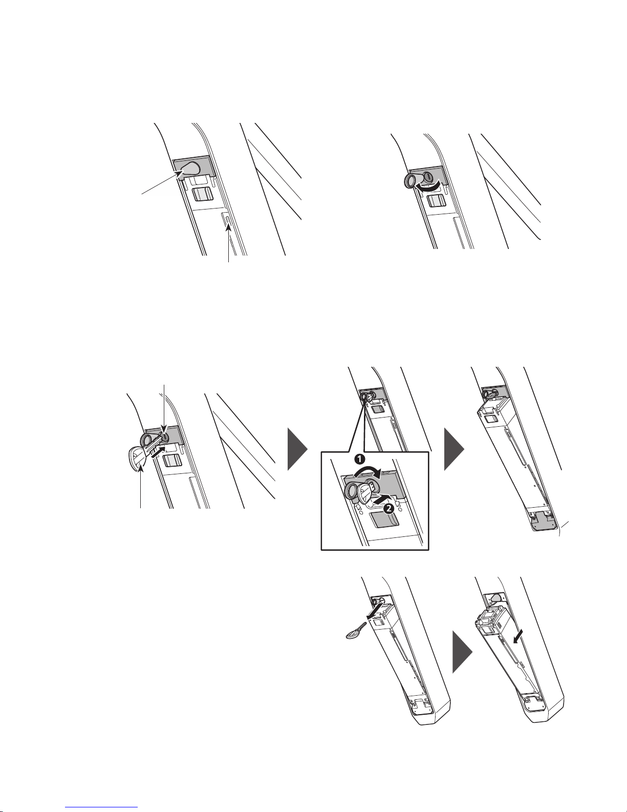
BT-E8020
•
This procedure is an example using a frame whose battery is removed/installed from below.
•
If using a battery cover manufactured by another company, remove the battery cover before removing the battery.
1.
Open the keyhole cap.
Turn off the power, then open the keyhole cap.
Push power button to turn off the power.
Key hole cap
2.
Unlock the battery.
(1) Insert the key into the key cylinder in the battery mount.
(2) Turn the key.
The battery is unlocked. The plate spring holds the battery in place, preventing it from falling out.
Key cylinder
Key
3.
Remove the battery.
(1) Remove the key, then close the keyhole cap.
(2) Remove the battery carefully.
Page 26
24
NOTE
Do not install or remove the battery with the key left inserted on the battery mount or the keyhole cap left open.
The battery may be damaged if it comes into contact with the top (grip portion) of the key.
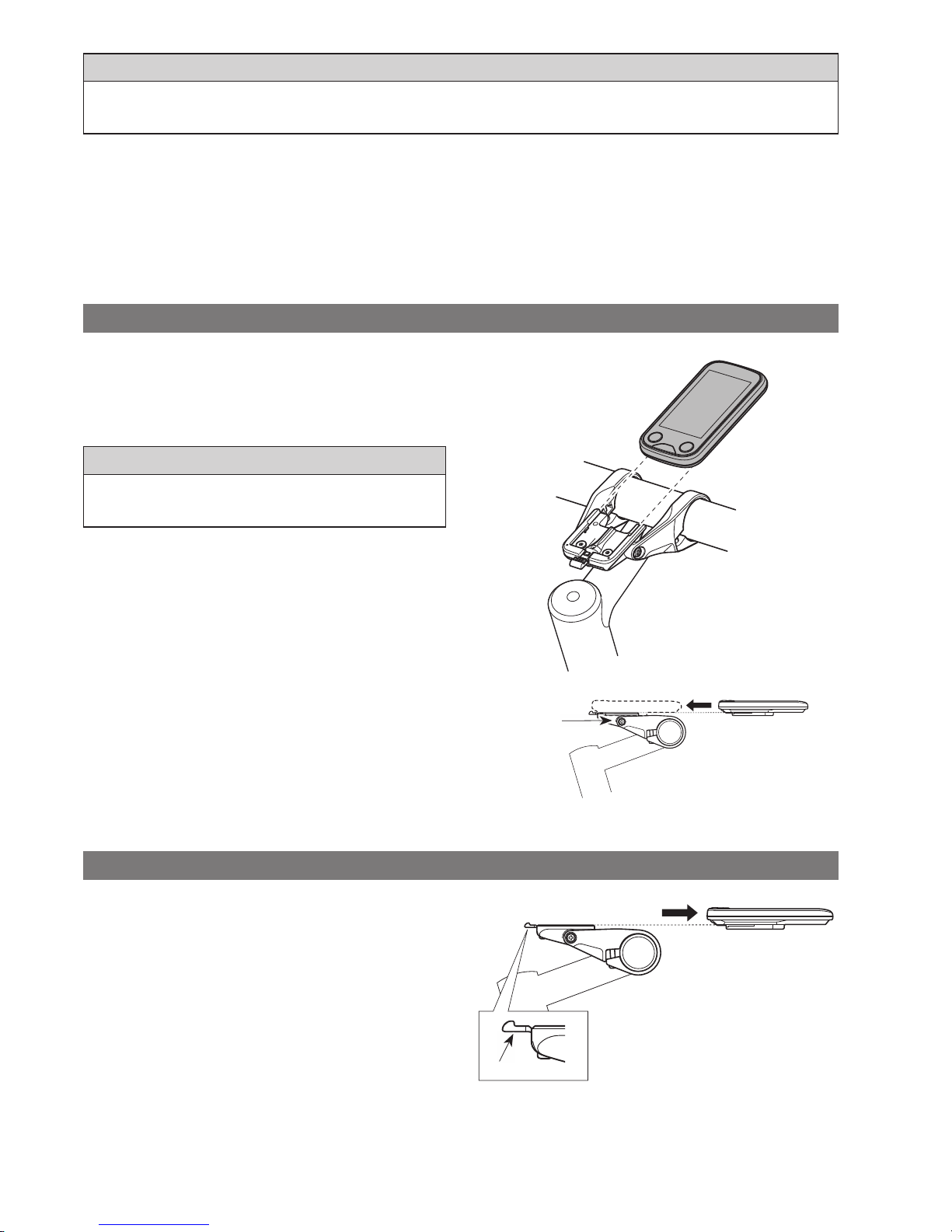
Installing and removing the cycle computer
The cycle computer can also be secured to the bicycle so that it cannot be easily removed. Please contact your place of
purchase for details.
Installing
1.
Slide the cycle computer onto the bracket.
2.
Insert the cycle computer securely until it clicks into
place.
NOTE
If the cycle computer is not correctly installed, the assist function
will not operate normally.
Bracket
Removing
1.
Slide out the cycle computer.
•
Push the lever firmly to release the cycle computer.
Lever
Page 27
25
Operation
Turning the power ON / OFF
•
The power cannot be turned on while charging.
•
If the bicycle has not moved for over 10 minutes, the power will automatically turn off (automatic power off function).
NOTE
Do not place your foot on the pedals when turning ON/OFF. This may cause a system error.
Powering on using the cycle computer with the cycle computer
•
If the built-in battery of the cycle computer isn't charged sufficiently, it will not power on.
•
The built-in battery of the cycle computer only charges when the cycle computer screen is on.
1.
Hold down the power button for 2 seconds.
Power button
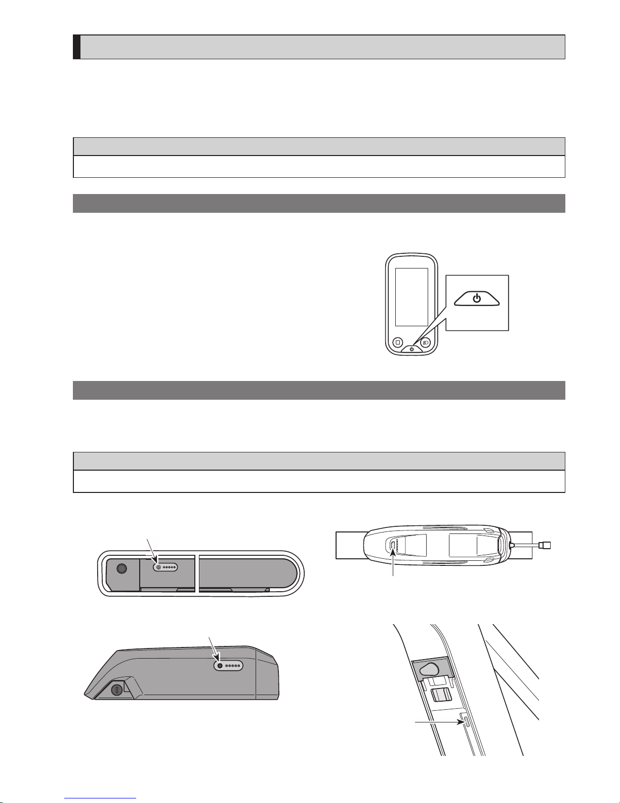
Powering on from the battery with the battery
It is possible to forcibly power off BT-E8010/BT-E8020 by holding down the power button for 6 seconds.
1.
Press the power button on the battery. The LED lamps will light up indicating remaining battery capacity.
NOTE
When turning on the power, check that the battery is firmly attached to the battery mount.
<BT-E6000/BT-E6001>
Power button
<BT-E8010/BT-E8014>
Power button
<BT-E6010>
Power button
<BT-E8020>
Power button
Page 28
26
Display when Power is ON
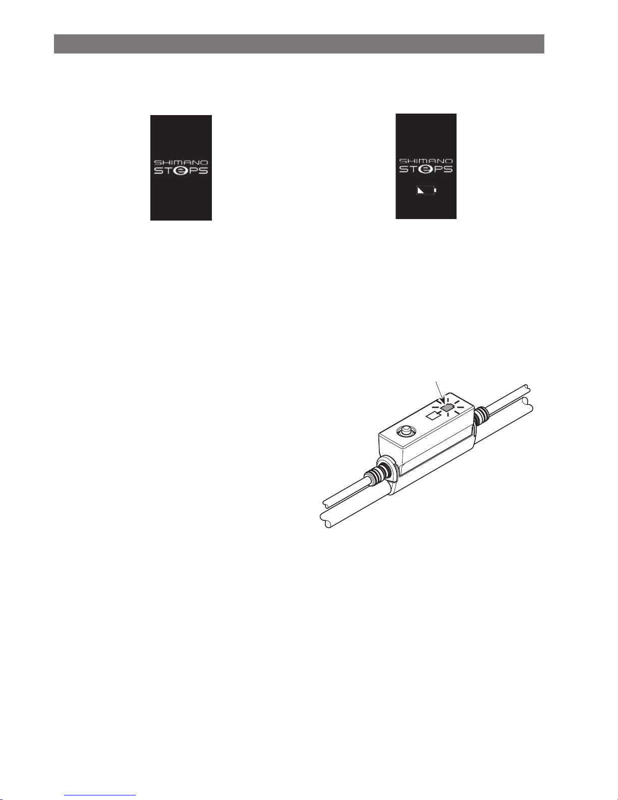
SC-E6100
When the power is turned ON, a screen similar to that shown below is displayed, and then switches to the basic screen.
Normal startup Battery level too low
*
The level of the cycle computer's built-in battery is too
low.
Turning the power ON with the cycle computer
connected to the bicycle will charge the cycle
computer's built-in battery.
EW-EN100
The LED lamp (outer side) turns ON.
LED lamp
(outer side)
Page 29
27
Basic operation
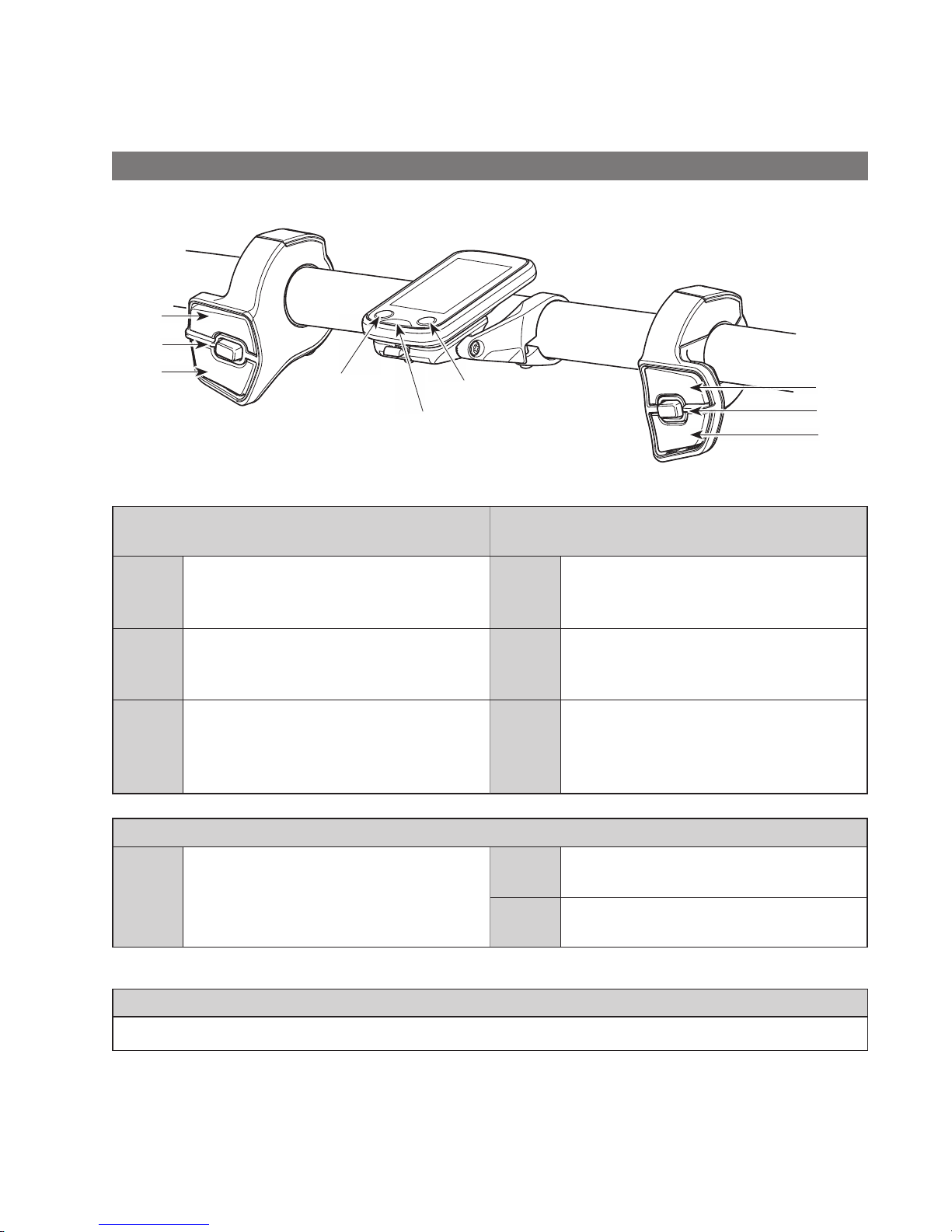
It is possible to change assigned functions for individual switches. For details, please consult with the dealer from which you
purchased the product.
Cycle computer (SC-E6100) and switch units (SW-E6010)
X
A
Y
X
A
Y
Left switch
Right switch
Light button
Power button
Function button
Left switch
(default: for assistance)
Right switch
(default: for electronic shifting)
Assist-X
At riding: increase assistance.
At setting: move the setting menu cursor,
adjust settings,etc.
Shift-X
At riding: shift gears to increase pedal
resistance.
Assist-Y
At riding: decrease assistance.
At setting: move the setting menu cursor,
adjust settings,etc.
Shift-Y
At riding: shift gears to decrease pedal
resistance.
Assist-A
At riding: change the travel data display on
the cycle computer.
At setting: switch between the screens, confirm
settings.
Shift-A
At riding: switch between automatic and
manual gear shifting (for electronic
internal geared hub).
Cycle computer (SC-E6100)
Function
button
At riding: change the travel data display on
the cycle computer.
At setting: switch between the screens, confirm
settings.
Light
button
Turn the lights ON/OFF.
Power
button
Turn the power ON/OFF.
NOTE
When the bicycle uses a rear derailleur, be sure to shift gears while pedaling.
Page 30
28
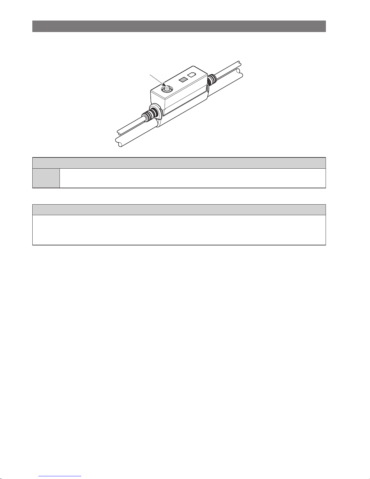
Junction [A] (EW-EN100)
EW-EN100 is used instead of cycle computer.
It is attached to the brake outer casing or brake hose and located near the handle bar.
Button
Junction [A]
Button
Press: change the assist mode each time you press it.
Press and hold (about 2 seconds): turn the light ON/OFF
NOTE
• To change to walk assist mode, a switch unit is required.
• The button does not recommend operating this unit while riding the bicycle. Please select your preffered assist mode before riding.
• For other functions assigned to the button, see "Setting (EW-EN100)."
Page 31
29
Turning the light ON / OFF
•
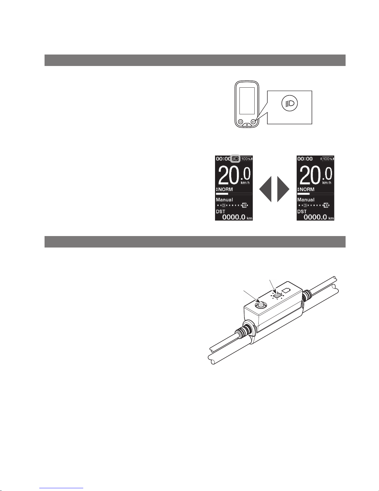
If your bicycle has the lights connected to drive unit, the lights can operate from the cycle computer or junction [A].
•
The light turns off in conjunction with the battery power. When the battery power is off, the light is off.
SC-E6100
1.
Press the light button.
•
Lights are turned on.
•
To turning off the lights, push the button again.
*
When the battery powered light is not connected and
[Backlight] is set to [MANUAL], pressing the light
button turns the cycle computer’s backlight on and
off.
When the light is
turned on
When the light is
turned off
Light button
EW-EN100
You cannot turn the light off while riding the bicycle.
1.
Press and hold (about 2 seconds) the button until the
lights turn ON/OFF.
The LED lamp (inner side) blinks green.
Button
LED lamp
(inner side)
Page 32
30
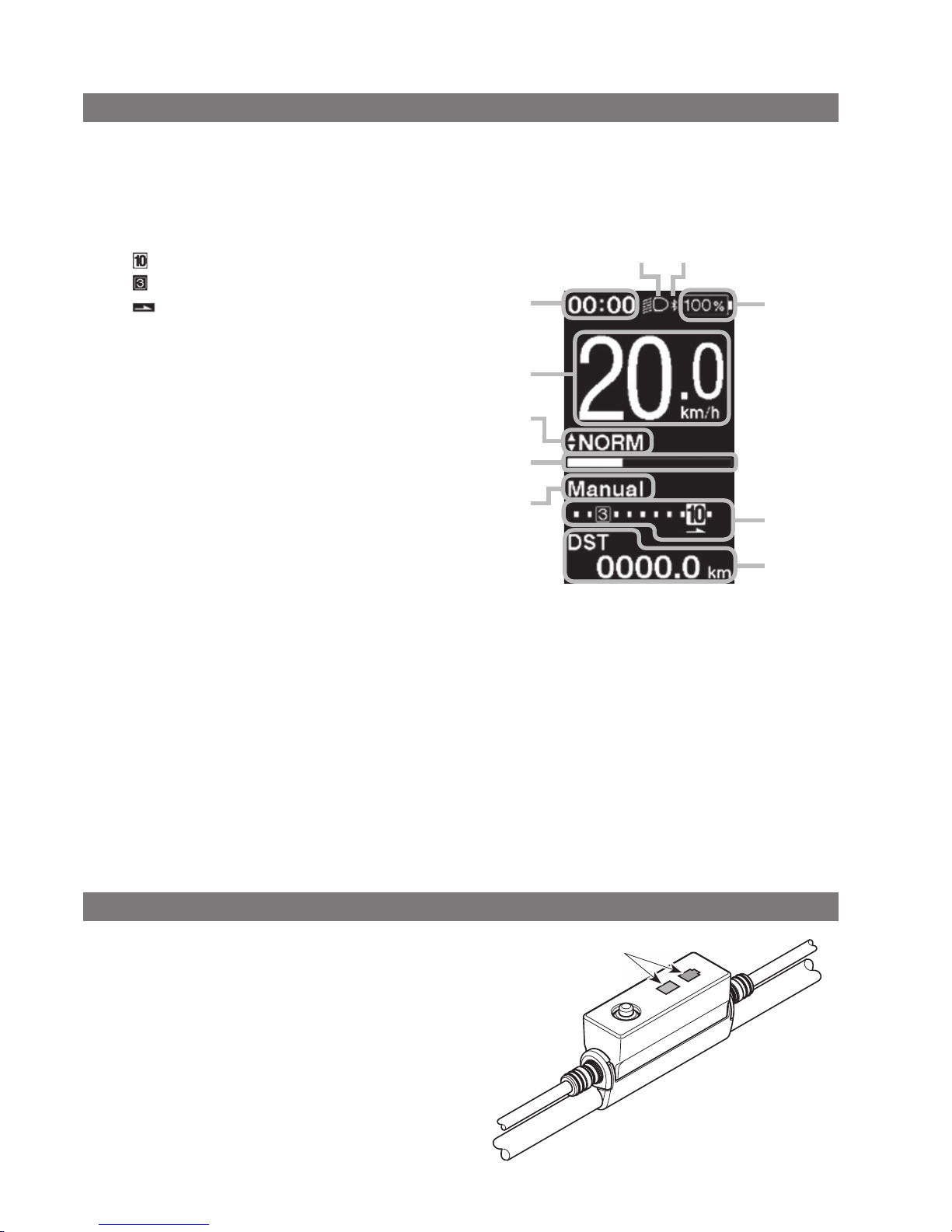
Basic status display
SC-E6100
Displays the status of your bicycle and travel data.
The gear position is only displayed when using electronic gear shifting.
(A)
Battery level indicator
(B)
Gear position display
Current gear position
Start mode gear position*
Shifting advice
This notifies you of the recommended timing
at which to shift based on the bicycle riding
conditions.
(C)
Travel data display
(D)
Gear shifting mode*
Displays current gear shifting mode as [Auto] or
[Manual].
(E)
Assist gauge
Displays assistance level.
(F)
Current assist mode
(G)
Current speed
(H)
Current time
(I)
Light icon
Indicates that the light connected to the drive unit
is lit.
(J)
Bluetooth® LE icon
Displayed when connected over Bluetooth LE.
*
Only for electronic gear shifting with internal
geared hub.
< Basic screen of SC-E6100 >
(H)
(G)
(A)
(I) (J)
(B)
(C)
(F)
(E)
(D)
EW-EN100
LED lamps indicate the following status.
•
Current battery level
•
Current assist mode
For details, see "Battery level indicator" and "Changing the
assist mode".
LED lamps
Page 33
31
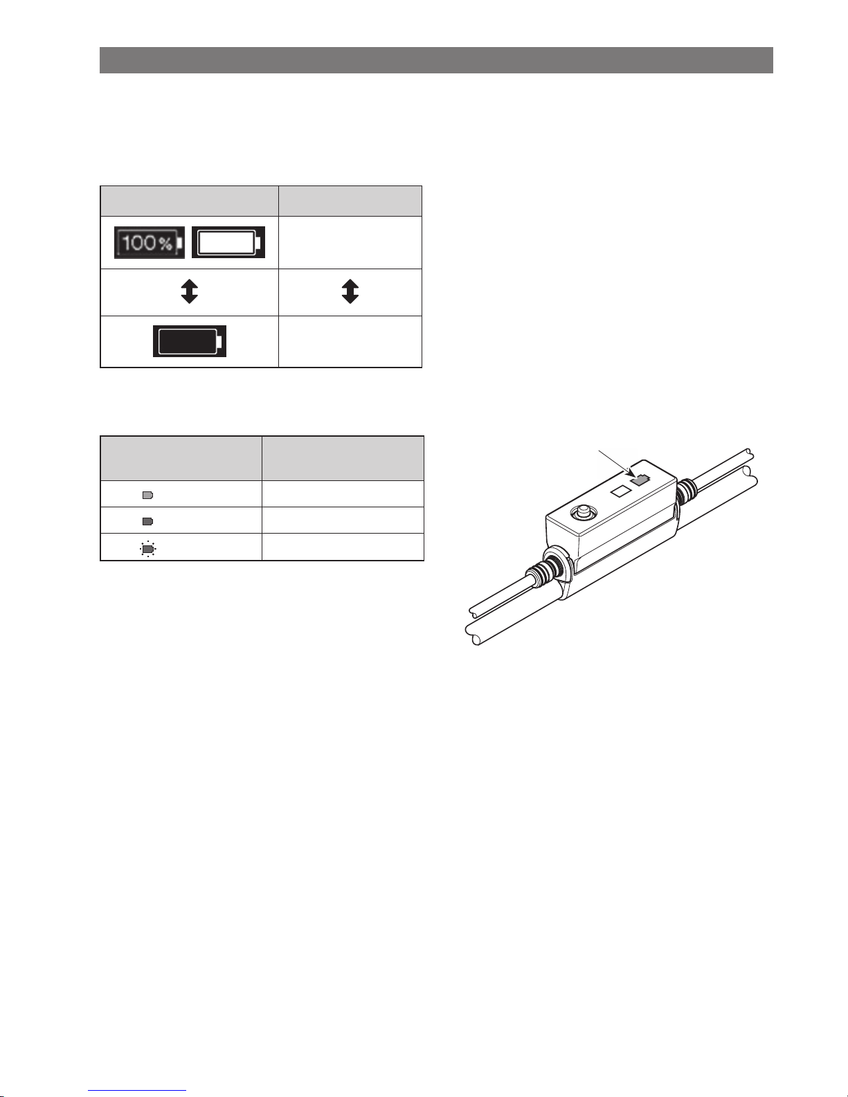
Battery level indicator
You can check the battery level while riding.
SC-E6100
The battery level is shown as a number and icon.
The display varies depending on the bicycle. You must connect to E-TUBE PROJECT to change this. Please contact a distributor
for details.
Display Battery level
100%
0%
EW-EN100
While power is turned on, the outer side LED lamp indicates the battery level.
LED lamp (outer side)
indication
Battery level
(Lit in green)
100 to 21%
(Lit in red)
20% or less
(blink in red)
Only a few left
LED lamp
(outer side)
Page 34
32
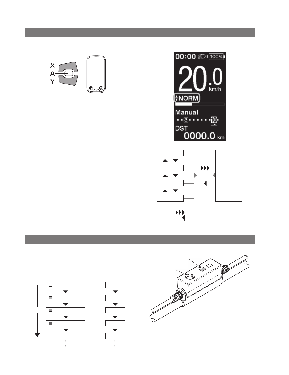
Changing the assist mode
Changing the assist mode with switch unit
1.
Press Assist-X or Assist-Y.
Assist
< SC-E6100 >
[HIGH]
[NORM]
[ECO]
[OFF]
[WALK]
XY
Long press Y
Short press X
Changing the assist mode with EW-EN100
1.
Press button.
Assist mode is changed each time you press it.
The LED lamp (inner side) indicates current assist mode.
Button
OFF
Lit in light blue
Lit in green
Lit in yellow
OFF
[OFF]
[ECO]
[NORM]
[HIGH]
[OFF]
LED lamp (inner side) indications Assist mode
LED lamp
(inner side)
Button
Page 35
33
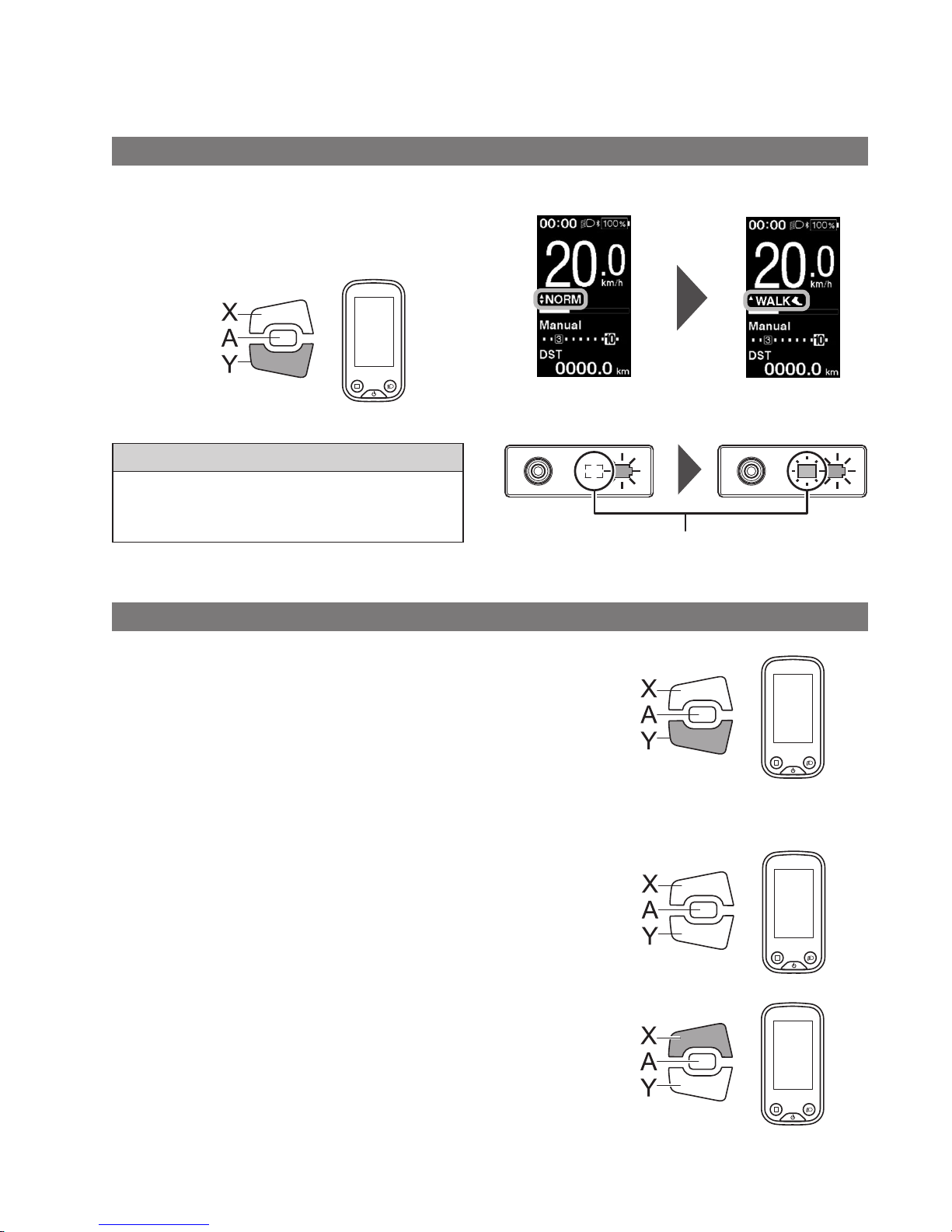
Walk assist mode
•
This mode may not be available in certain regions.
•
The walk assist function can operate at a maximum of 6 km/h. The assistance level and speed vary with the gear position.
Switch to walk assist mode
1.
Press and hold Assist-Y (about 2 seconds) until the
following occurs.
SC-E6100: [WALK] is displayed on the screen
EW-EN100: LED lamp (inner side) lights up blue
Assist
2 Sec.
NOTE
A warning tone will sound while switching is in progress if it is
not possible to switch to [WALK] mode because the current
speed is not [0 km/h] or there is pressure on the pedals etc.
< SC-E6100 >
< EW-EN100 >
LED lamp (inner side)
Assist OFF Walk assist mode enabled
Operation of walk assist function
1.
While in walk assist mode, press and hold down Assist-Y.
•
Start the walk assist function.
•
If Assist-Y is not operated for over 1 minute, the assist
mode will change to [OFF].
•
If the switch unit is connected to EW-EN100, the LED
lamp (inner side) blinks blue when the above
operation is performed.
2.
Hold the handlebar and push the bicycle carefully.
Assist
Hold down
3.
To stop the walk assist function, release Assist-Y.
Assist
Release
4.
To exit the walk assist mode, press the Assist-X button.
Assist
Page 36
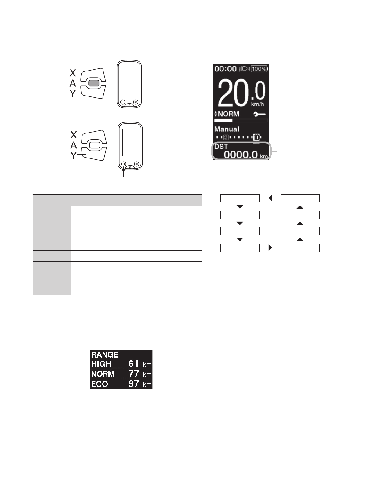
34
Switching the travel data display (SC-E6100)
1.
The type of travel data displayed changes each time you
press Assist-A or the cycle computer's function button.
Assist
or
Assist
Function button
< SC-E6100 >
Travel data
display
Display item Description
[DST] Traveling distance
*1
[ODO] Cumulative distance
[RANGE] Travelable distance
*2
[RANGE] Travelable distance for each assist mode
*2 *3 *4
[TIME] Travelable time
*4
[AVG] Average speed
*4
[MAX] Maximum speed
*4
[CADENCE] Your crank rotation speed
*4
[DST] [CADENCE]
[ODO] [MAX]
[RANGE] [AVG]
[RANGE] [TIME]
*1 When [DST] is displayed, press Assist-A for 2 seconds to reset the all
all travel data.
*2 Travelable distance figures are approximations to be used for
reference purposes only.
*3 This data is displayed as follows. Gear shifting mode and gear
position are not displayed.
*4 Optional item: You can configure the display settings in E-TUBE
PROJECT. For details, refer to the "Connection and communication
with devices".
Page 37
35
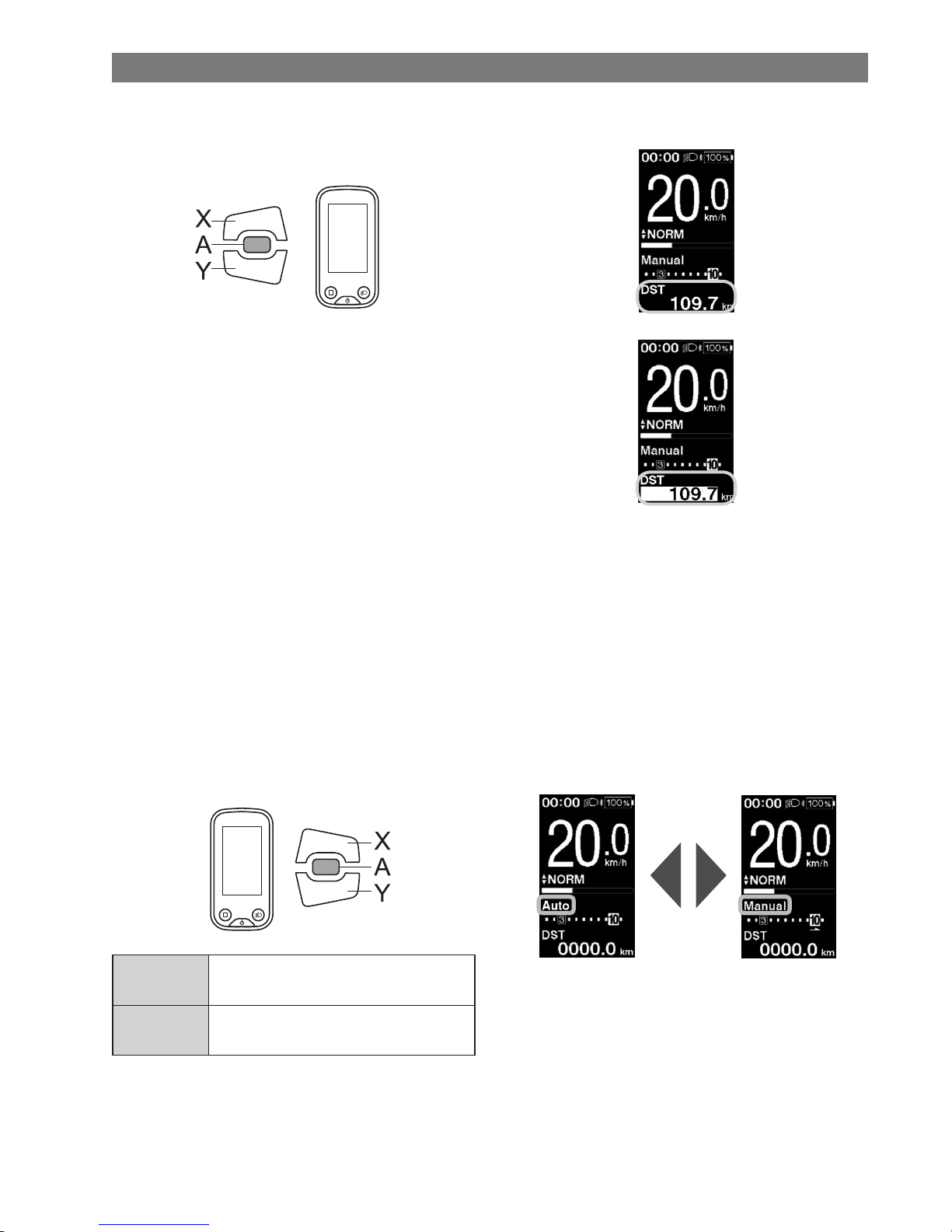
Clearing the traveling distance
You can clear the traveling distance in the main screen. When the traveling distance is cleared, [TIME] (travelable time),
[AVG] (average speed), [MAX] (maximum speed) are also cleared.
1.
Press Assist-A to change the travel data display to [DST].
Assist
2.
Press and hold down Assist-A until the value below the
[DST] display blinks.
3.
Press Assist-A again.
•
Travel data is cleared.
•
The [DST] value stops blinking and the screen takes
resets to the basic screen after being left alone for 5
seconds.
Switch the gear shifting mode
This function is only for electronic gear shifting by internal geared hub.
1.
Press Shift-A at the basic screen.
Each press switches between [Manual] and [Auto].
Shift
[Auto]
Automatically shift gears according to
the pedal load.
[Manual]
Manually operate the gear-shift
mechanism for electronic gear shifting.
< SC-E6100 >
Automatic
Manual
Page 38
36
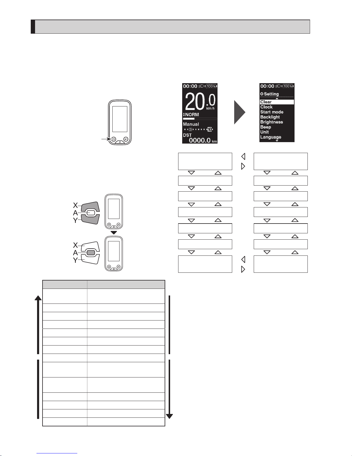
Setting menu (SC-E6100)
Launching
1.
Stop your bicycle.
2.
Press and hold the function button.
When the display changes to the setting screen,
release the button.
Function button
< Basic screen > < Setting menu screen >
3.
Select the menu item.
(1) Press Assist-X or Assist-Y to move the cursor on
setting menu.
(2) Press Assist-A.
The display changes to the selected menu item.
Assist
Configurable items Details
X
[Clear]
Reset the traveling distance or
the setting values.
Y
[Clock] Set the current time.
[Start mode]
*1
Set the start gear.
[Backlight] Configure the display backlight.
[Brightness] Set the display brightness.
[Beep] Turning the beep sound ON/OFF.
[Unit] Select between km and miles.
[Language] Set the display language.
[Font color]
Select the display character color
between black and white.
[Adjust]
*2
Adjust the electronic gear
shifting unit
[Shift timing] Adjust the shift timing
[Shifting advice] Turning the shifting advice ON/OFF
[RD protection reset]*3Actibating RD protection reset
[Exit] Return to the main screen.
[Clear]
[Unit]
[Clock]
[Start mode]
[Backlight]
[Brightness]
[Beep]
[Exit]
[Language]
[RD protection reset]
[Adjust]
[Shifting advice]
[Font color]
[Shift timing]
*
1 Only for electronic shifting with internal geared hub
*
2 Only for electronic shifting
*
3 Only for electronic shifting with rear derailleur
Page 39
37
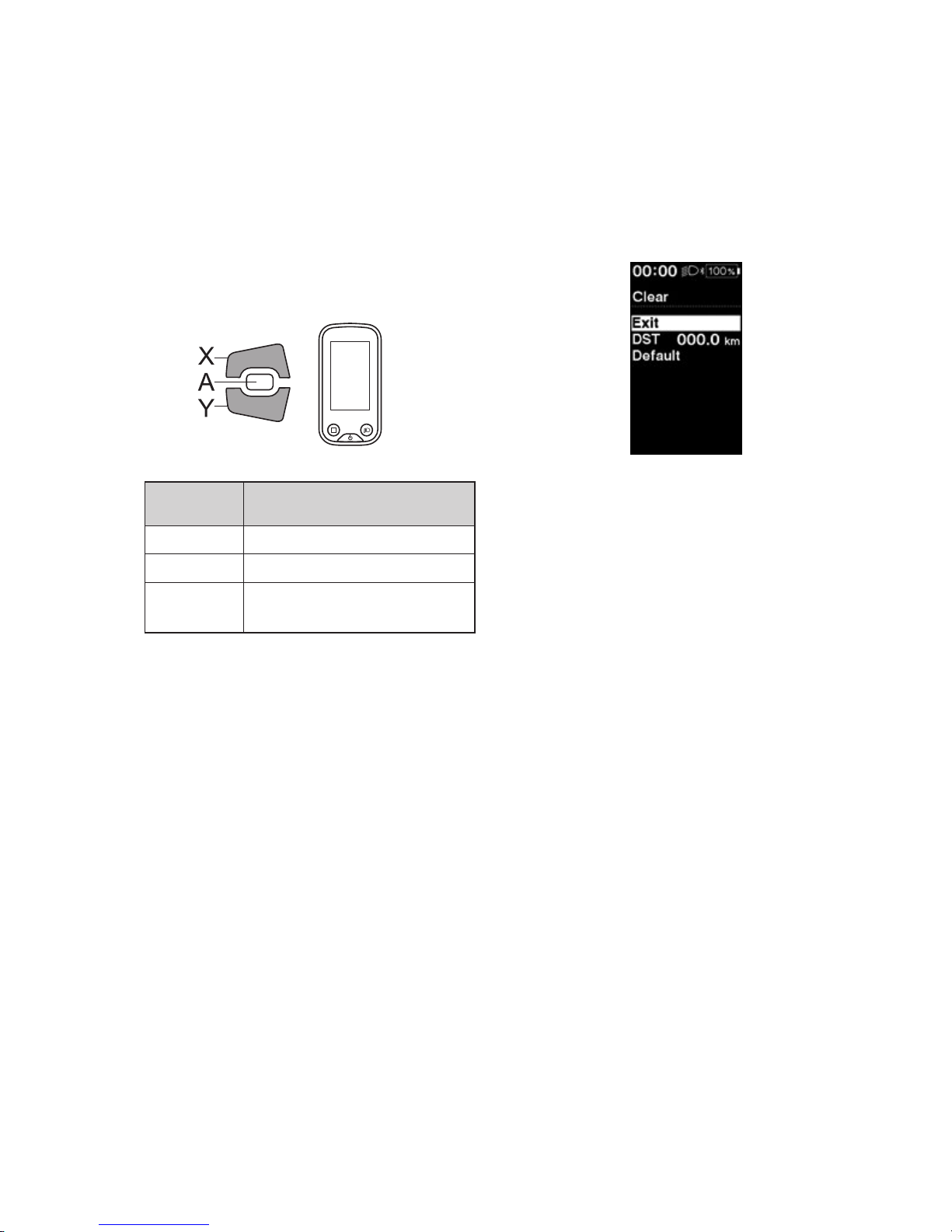
Clear
Reset the traveling distance or the setting values.
When the [DST] (traveling distance) is cleared, [TIME] (travelable time), [AVG] (average speed) and [MAX] (maximum
speed ) are also cleared.
1.
Enter the [Clear] menu.
(1) Launch the setting menu.
(2) Press Assist-X or Assist-Y to select [Clear], then
press Assist-A.
2.
Press Assist-X or Assist-Y to select what you want to
reset.
Assist
Configurable
items
Details
[Exit] Return to setting menu.
[DST] Reset the traveling distance
[Default]
Reset the setting values of the
cycle computer.
Items and default values reset by [Default] are as
follows:
•
[Backlight]: ON
•
[Beep]: ON
•
[Unit]: km
•
[Language]: English
•
[Brightness]: 3
•
[Font color]: White
3.
Press Assist- A to reset the selected item.
*
The screen will automatically return to the setting
menu screen.
Page 40
38
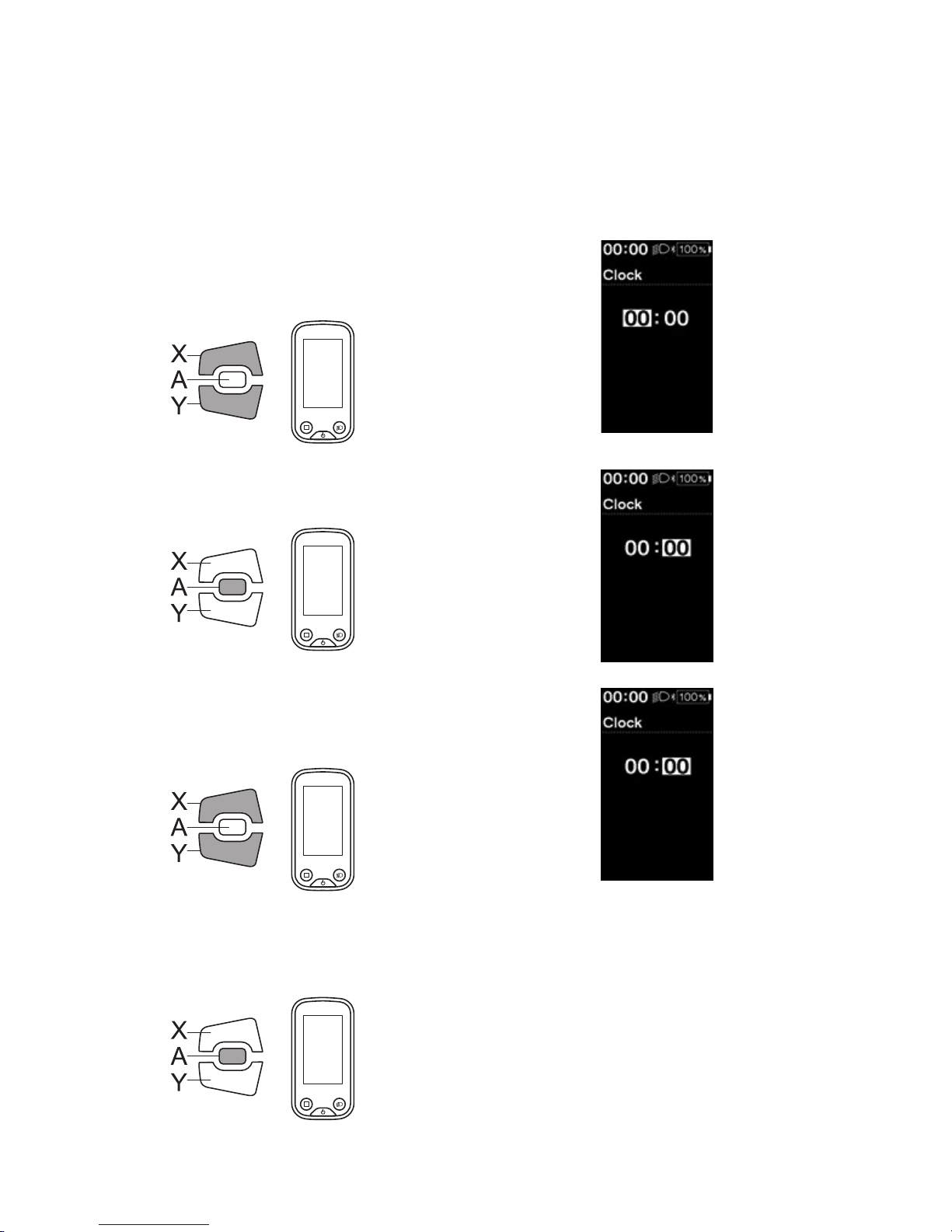
Clock
Sets the current time. First set "hour" then "minute".
In step 2 and 4 in below procedure, you can change the values quickly by holding down Assist-X or Assist-Y.
1.
Enter the [Clock] menu.
(1) Launch the setting menu.
(2) Press Assist-X or Assist-Y to select [Clock], then
press Assist-A.
2.
Press Assist-X or Assist-Y to adjust the time.
•
Press Assist-X to increase the value.
•
Press Assist-Y to decrease the value.
Assist
3.
Press Assist-A to confirm the setting.
The cursor moves to minutes value.
Assist
4.
Press Assist-X or Assist-Y to adjust the minutes value.
•
Press Assist-X to increase the value.
•
Press Assist-Y to decrease the value.
Assist
5.
Press Assist-A to confirm the setting.
*
The screen will automatically return to the setting
menu screen.
Assist
Page 41
39
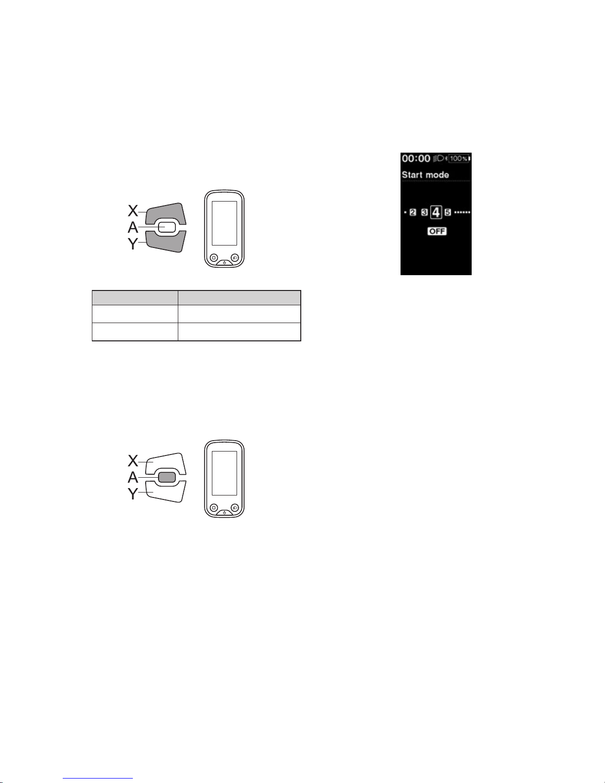
Start mode
Set the start gear of the start mode function.
It is possible to have the gear automatically shifted to the number set here when you start moving from a standstill.
1.
Enter the [Start mode] menu.
(1) Launch the setting menu.
(2) Press Assist-X or Assist-Y to select [Clock], then
press Assist-A.
2.
Press Assist-X or Assist-Y to move the cursor to the
item you want to configure.
Assist
Configurable items Details
[OFF] No setting
[1 - 11] 1-11-speed *
*
The setting will vary depending on the bicycle
derailleur.
3.
Press Assist-A to confirm the setting.
*
The screen will automatically return to the setting
menu screen.
Assist
Page 42
40
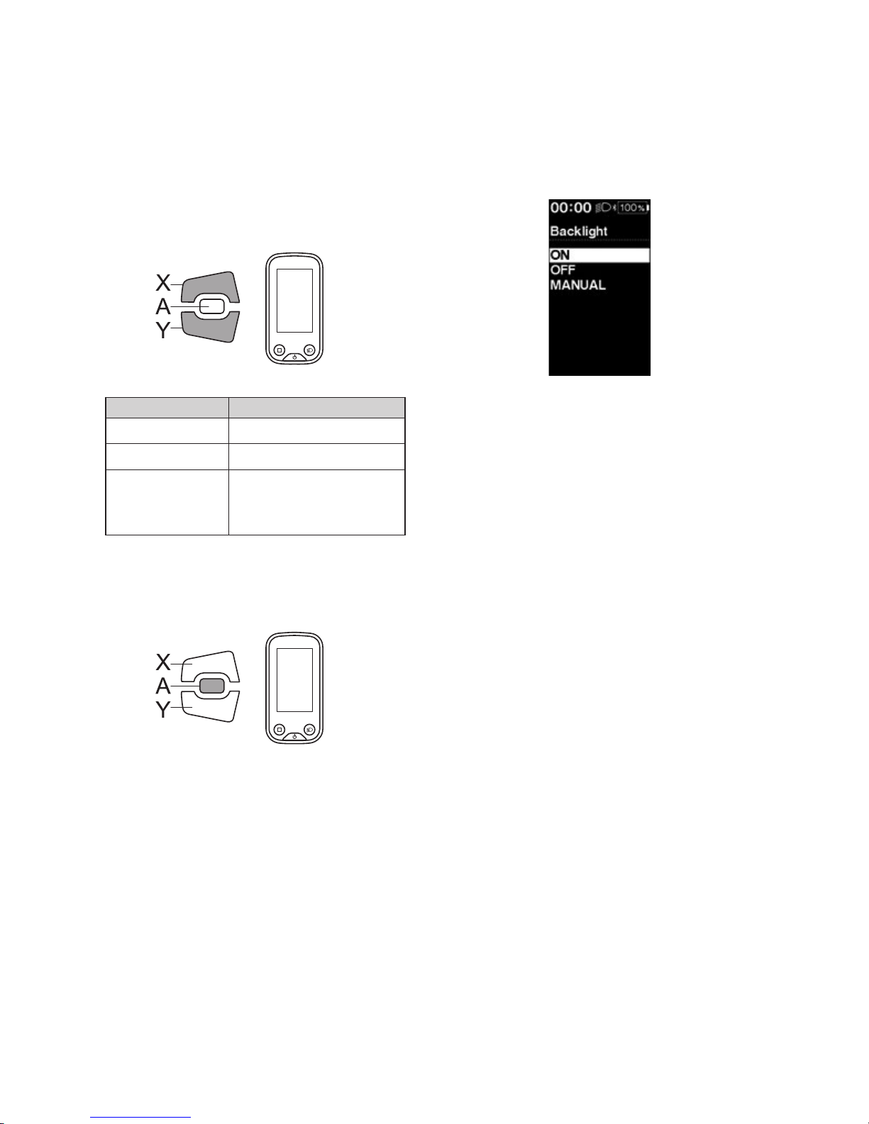
Backlight
Configure the display backlight.
1.
Enter the [Backlight] menu.
(1) Launch the setting menu.
(2) Press Assist-X or Assist-Y to select [Backlight], then
press Assist-A.
2.
Press Assist-X or Assist-Y to move the cursor to the
item you want to configure.
Assist
Configurable items Details
[ON] Always turned on
[OFF] Always turned off
[MANUAL]
Turns on and off in
conjunction with the
battery-powered light
3.
Press Assist-A to confirm the setting.
*
The screen will automatically return to the setting
menu screen.
Assist
Page 43
41
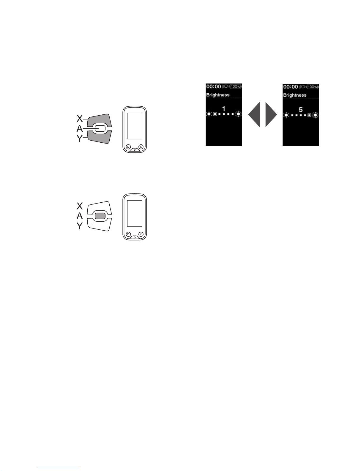
Brightness
Set the display brightness.
1.
Enter the [Brightness] menu.
(1) Launch the setting menu.
(2) Press Assist-X or Assist-Y to select [Brightness], then
press Assist-A.
2.
Press Assist-X or Assist-Y to adjust the brightness.
Brightness can be adjusted to one of five levels.
Assist
3.
Press Assist-A to confirm the setting.
*
The screen will automatically return to the setting
menu screen.
Assist
Page 44
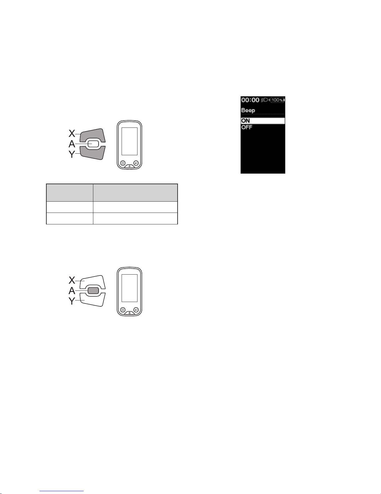
42
Beep
Turn the beep sound ON/OFF.
Even when [Beep] is set to [OFF], a beep will sound when there is a misoperation, system error, etc.
1.
Enter the [Beep] menu.
(1) Launch the setting menu.
(2) Press Assist-X or Assist-Y to select [Beep], then
press Assist-A.
2.
Press Assist-X or Assist-Y to move the cursor to the
item you want to configure.
Assist
Configurable
items
Details
[ON] Enable beeps
[OFF] Disable beeps
3.
Press Assist-A to confirm the setting.
*
The screen will automatically return to the setting
menu screen.
Assist
Page 45
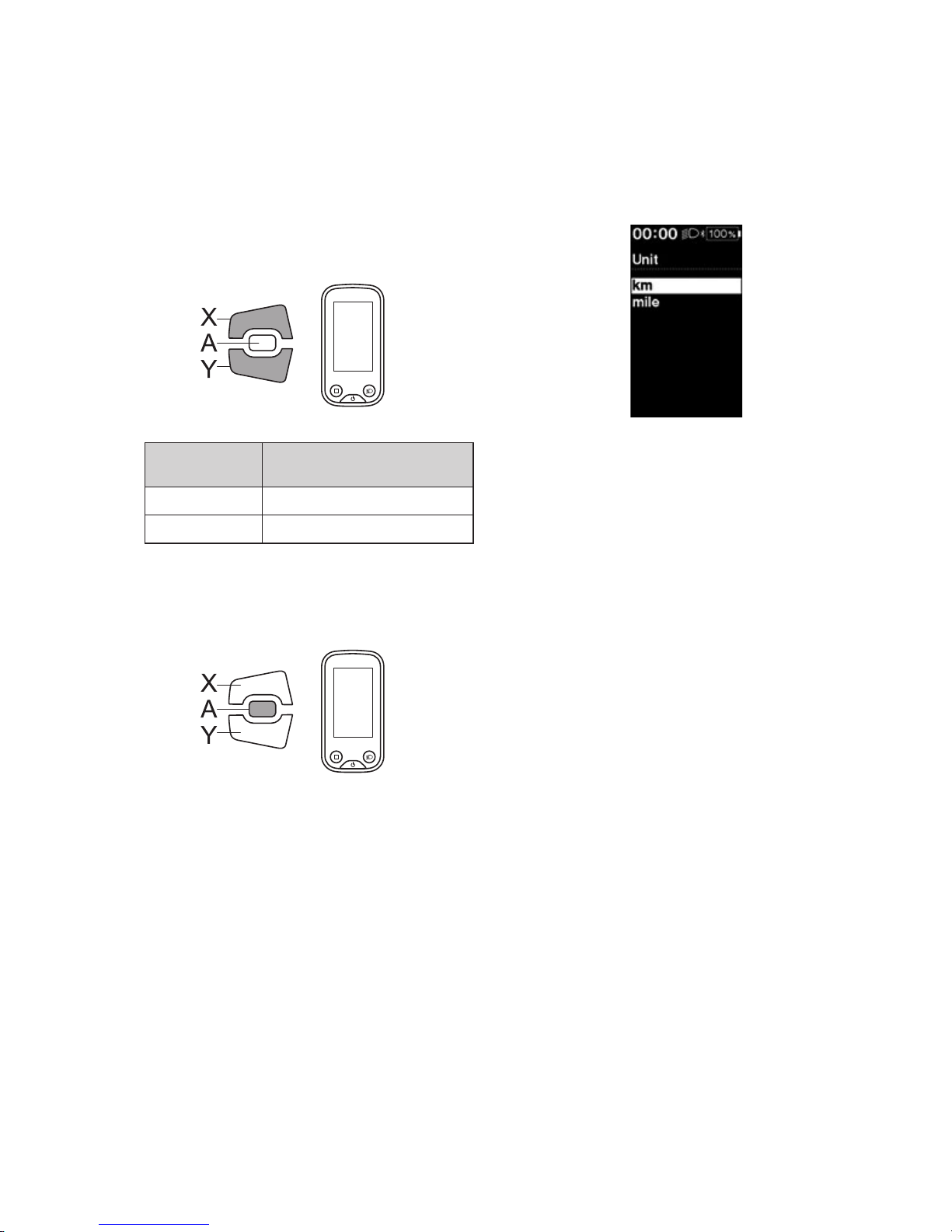
43
Unit
Toggle between kilometers and miles.
1.
Enter the [Unit] menu.
(1) Launch the setting menu.
(2) Press Assist-X or Assist-Y to select [Unit], then press
Assist-A.
2.
Press Assist-X or Assist-Y to move the cursor to the
item you want to configure.
Assist
Configurable
items
Details
[km] Displayed in km
[mile] Displayed in miles
3.
Press Assist-A to confirm the setting.
*
The screen will automatically return to the setting
menu screen.
Assist
Page 46
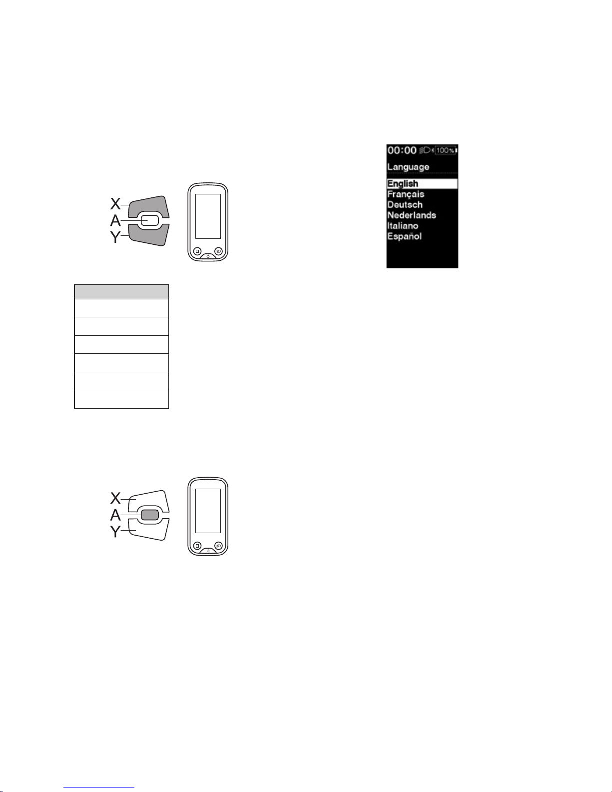
44
Language
Set the display language.
1.
Enter the [Language] menu.
(1) Launch the setting menu.
(2) Press Assist-X or Assist-Y to select [Language], then
press Assist-A.
2.
Press Assist-X or Assist-Y to move the cursor to the
item you want to configure.
Assist
Configurable items
[English]
[Français]
[Deutsch]
[Nederlands]
[Italiano]
[Español]
3.
Press Assist-A to confirm the setting.
*
The screen will automatically return to the setting
menu screen.
Assist
Page 47
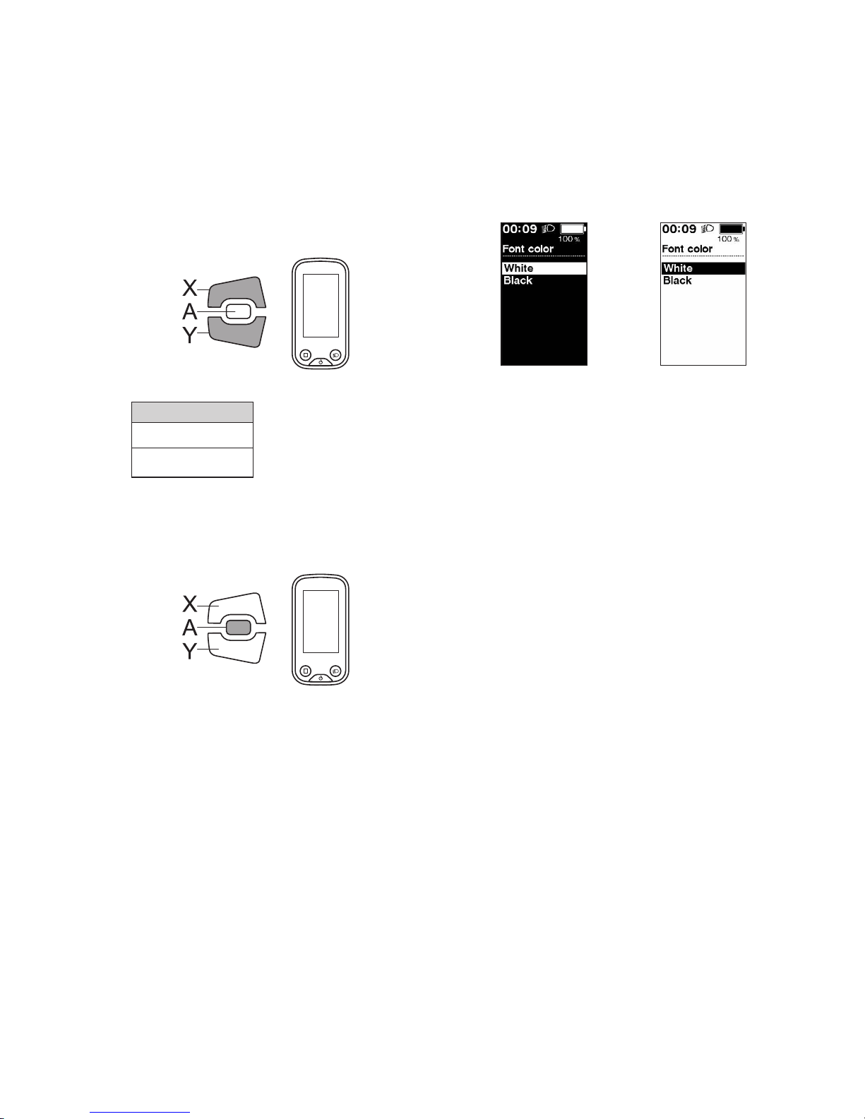
45
Font color
Toggle the font character color between black and white.
1.
Enter the [Font color] menu.
(1) Launch the setting menu.
(2) Press Assist-X or Assist-Y to select [Font color], then
press Assist-A.
2.
Press Assist-X or Assist-Y to move the cursor to the
item you want to configure.
Assist
Configurable items
[White]
[Black]
White
Black
3.
Press Assist-A to confirm the setting.
*
The screen will automatically return to the setting
menu screen.
Assist
Adjust
If you need to adjust the rear shifting unit, contact the place of purchase.
Page 48
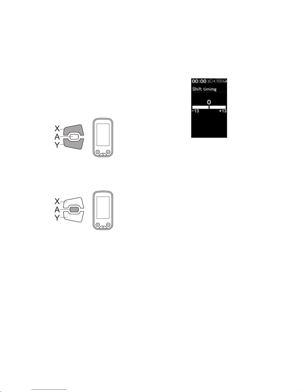
46
Shift timing
Adjust the shift timing of the automatic shift mode.
This setting is used when shifting advice is displayed during manual shift mode.
1.
Enter the [Shift timing] menu.
(1) Launch the setting menu.
(2) Press Assist-X or Assist-Y to select [Shift timing],
then press Assist-A.
2.
Press Assist-X or Assist-Y to adjust the values.
•
Pressing Assist-X to increase the value adjusts shift
timing to make pedaling easier.
•
Pressing Assist-Y to decrease the value adjusts shift
timing to make pedaling harder.
Assist
3.
Press Assist-A to confirm the setting.
*
The screen will automatically return to the setting
menu screen.
Assist
Page 49
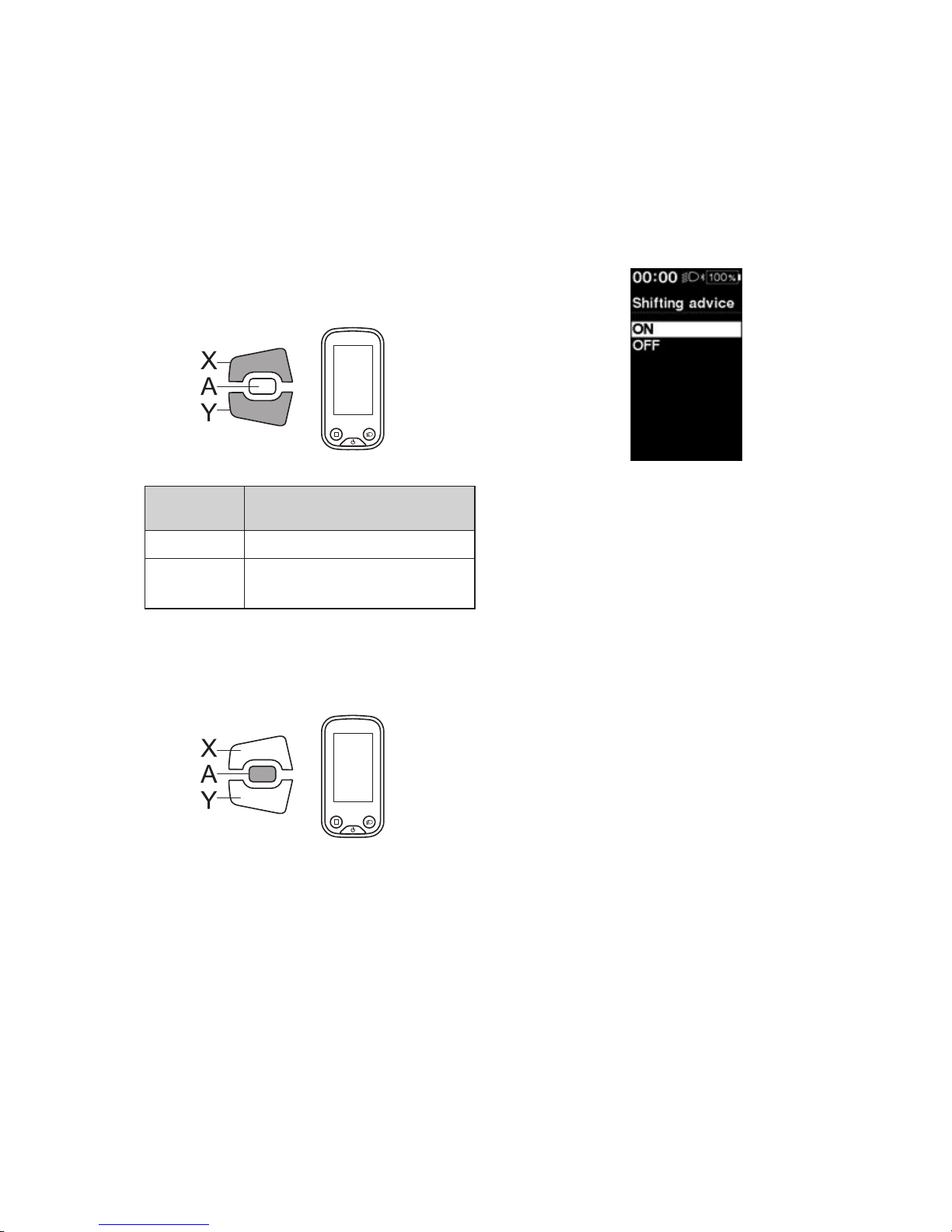
47
Shifting advice
Turn the shifting advice function ON/OFF.
If turned [ON], this notifies you of the recommended timing at which to shift based on the bicycle riding conditions
during manual shifting mode.
1.
Enter the [Shifting advice] menu.
(1) Launch the setting menu.
(2) Press Assist-X or Assist-Y to select [Shifting advice],
then press Assit-A.
2.
Press Assist-X or Assist-Y to move the cursor to the
item you want to configure.
Assist
Configurable
items
Details
[ON] Enable the shifting advice function
[OFF]
Disable the shifting advice
function
3.
Press Assist-A to confirm the setting.
*
The screen will automatically return to the setting
menu screen.
Assist
Page 50
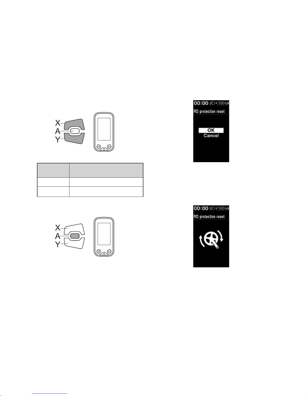
48
RD protection reset
In order to protect the system from falls etc., if the bicycle is subjected to a strong impact, the “RD Protection function”
is enabled. The connection between the motor and the link will be momentarily severed so that the rear derailleur can
no longer operate.
Executing “RD Protection Reset” restores the connection between the motor and the link, as well as the function of the
rear derailleur.
1.
Enter the [RD protection reset] menu.
(1) Launch the setting menu.
(2) Press Assist-X or Assist-Y to select [RD protection
reset], then press Assist-A.
2.
Press Assist-X or Assist-Y to select [OK].
Assist
Configurable
items
Details
[OK] Execute the “RD protection reset”.
[Cancel] Cancel and return to setting menu.
3.
Press Assist- A.
Assist
4.
Rotate the crankarm.
Connection of motor and the link is restored.
Exit
Return to the main screen.
1.
Launch the setting menu.
2.
Press Assist-X or Assist-Y to select [Exit], then press Assist-A.
*
The screen will automatically return to the setting menu screen.
Page 51
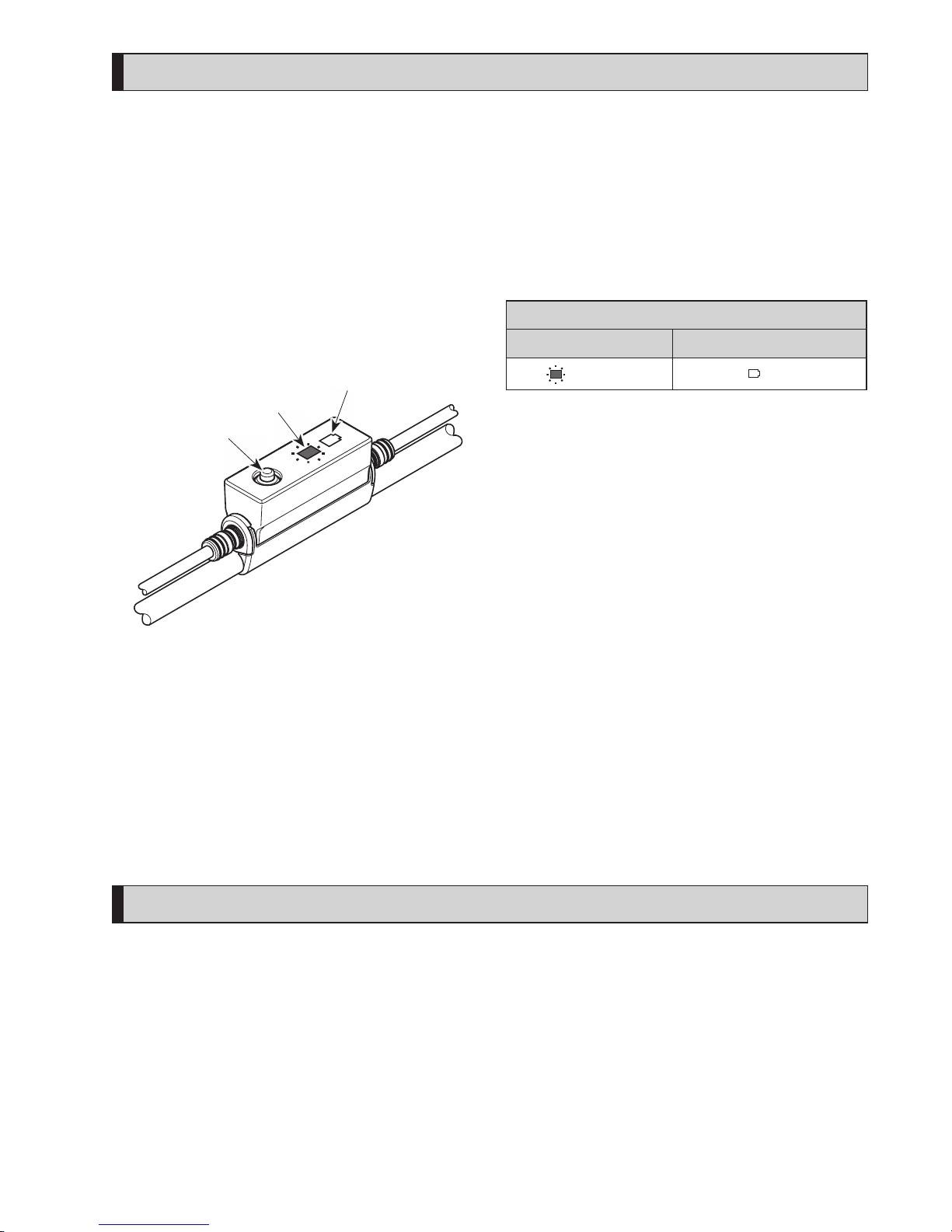
49
Settings (EW-EN100)
The setting function can not be used while riding the bicycle.
RD protection reset
In order to protect the system from falls etc., if the bicycle is subjected to a strong impact, the “RD Protection function” is
enabled. The connection between the motor and the link will be momentarily severed so that the rear derailleur can no
longer operate.
Executing “RD Protection Reset” restores the connection between the motor and the link, as well as the function of the rear
derailleur.
1.
Press and hold the button (about 8 second) until the
LED lamps respond as shown in the table on the right.
LED lamp
(outer side)
LED lamp
(inner side)
Button
2.
Rotate the crankarm.
Connection of motor and the link is restored.
RD protection reset.
LED lamp (inner side) LED lamp (outer side)
Blinks red
OFF
Adjust
You can adjust gear shifting only when using an electronic gear shifting unit.
If you need to adjust the derailleur, contact the place of purchase.
Drive unit setting data backup function
The data saved to the drive unit is usually backed up automatically. However, performing the following operations will cause
a message to appear asking whether or not you want to update the backup data.
•
Reinstalling the cycle computer on a bicycle with different settings.
•
Changing the drive unit settings for an E-TUBE PROJECT.
Page 52

50
Connection and communication with devices
The system can be configured and firmware can be updated when the bicycle is connected to a device (PC/tabret).
You need E-TUBE PROJECT to configure SHIMANO STEPS and update firmware.
Download an E-TUBE PROJECT from the support website (http://e-tubeproject.shimano.com).
For information on how to install an E-TUBE PROJECT, check the support website.
•
Connecting to devices is not possible while charging.
•
You need SM-PCE1 and SM-JC40 / JC41 to connect SHIMANO STEPS to a PC.
•
Firmware is subject to change without notice.
If necessary, contact the place of purchase.
About wireless functions
Functions
The latest functions can be checked by updating the software via E-TUBE PROJECT. For details, consult the place of purchase.
ANT connection
The wireless unit transmits all the information from the main screen of the cycle computer.
Bluetooth® LE connection
E-TUBE PROJECT for smartphones/tablets may be used if a Bluetooth LE connection is established using a smartphone/tablet.
How to make a connection
To make a connection, the device connected to SC-E6100 or EW-EN100 needs to be in connection mode. For information on
how to switch the device to connection mode, refer to the manual for the device.
2.4 GHz digital wireless system
2.4 GHz-frequency digital wireless technology is the same technology used for wireless LAN communication.
However, on very rare occasions, the following and places may generate strong electromagnetic waves and interference,
which may result in incorrect measurements.
•
When near televisions, computers, radios and motors/engines, or when riding in car and trains.
•
When near railroad crossings or railway tracks, and around television transmitting stations and radar bases.
•
Around other wireless computers or digitally controlled light.
Specifications for wireless system
Model no. SC-E6100 EW-EN100
Frequency band 2402–2480 MHz 2402–2480 MHz
Maximum radio-frequency power +4 dBm +4 dBm
Firmware version 4.0.0 4.0.0
Page 53
51
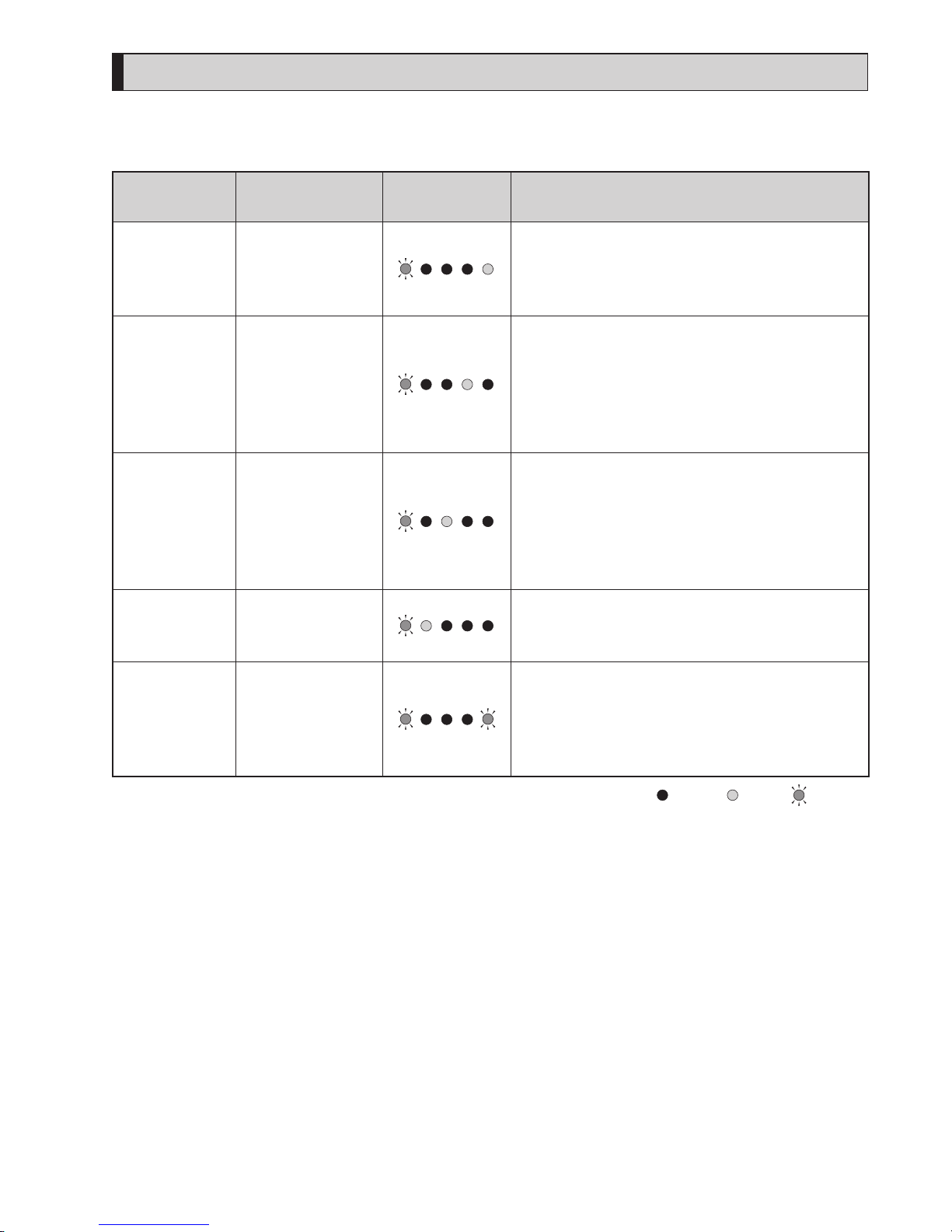
Errors and remedies
Battery LED lamp error indications
System errors and similar warnings are indicated by the battery LED lamps through various lighting patterns.
Error indication
type
Indication condition
Lighting
pattern *1
Recovery
System error
Communication error
with the bicycle
system
Make sure that the cable is not loose or improperly
connected.
If the situation does not improve, contact the place of
purchase.
Temperature
protection
If the temperature
exceeds the
guaranteed
operating range, the
battery output is
turned off.
Leave the battery in a cool place away from direct
sunlight until the internal temperature of the battery
decreases sufficiently.
If the situation does not improve, contact the place of
purchase.
Security
authentication
error
This is displayed if a
genuine drive unit is
not connected.
This is displayed if
any of the cables are
disconnected.
Connect a genuine battery and drive unit.
Check the condition of the cables.
If the situation does not improve, contact the place of
purchase.
Charging error
This is displayed if an
error occurs during
charging.
Remove the charger from the battery and press the
power button, if an error appears contact an agency.
Battery
malfunction
Electrical failure
inside the battery
Connect the charger to the battery and then remove
the charger. Press the power button with only the
battery connected.
If an error appears with only the battery connected,
contact the place of purchase.
*1
: Not lit : Lit up : Blinking
Page 54
52
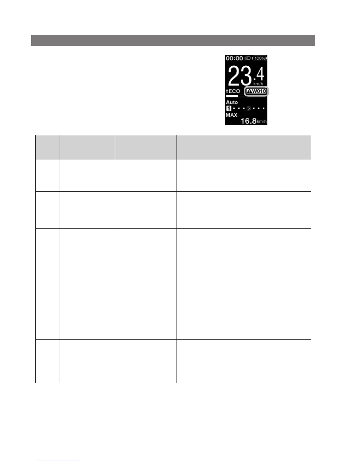
Error messages on the cycle computer
Warnings
This disappears if the error is fixed.
Code
Display
preconditions
Operational restrictions
while warning is
displayed
Remedy
W010
The temperature of
the drive unit is high.
The level of assistance
may decrease.
Stop using the assist function until the temperature of
the drive unit drops.
If the situation does not improve, contact the place of
purchase.
W011
The traveling speed
cannot be detected.
The maximum speed up to
which power assistance is
provided may decrease.
(Power assistance is provided
up to 25 km/h in top gear.)
Check that the speed sensor is properly installed.
If the situation does not improve, contact the place of
purchase.
W030
Two or more assist
switches are
connected to the
system.
Gear shifting is not
available for electronic
derailleurs.
Change the assist switch to the gear shifting switch, or
connect only one assist switch and turn on the power
again.
If the situation does not improve, contact the place of
purchase.
W032
An electronic
derailleur may have
been installed in
place of a
mechanical
derailleur.
Power assistance
provided in [WALK]
mode may be lower
than usual.
*
The walk assist mode
function may not
available in certain
regions.
Reinstall the derailleur for which the system is
configured to support.
If the situation does not improve, contact the place of
purchase.
-
A communication
error between the
drive unit and the
motor unit was
detected.
Gear shifting is not
available for electronic
derailleurs.
Check that the cable is properly connected between the
drive unit and the motor unit.
If the situation does not improve, contact the place of
purchase.
Page 55
53
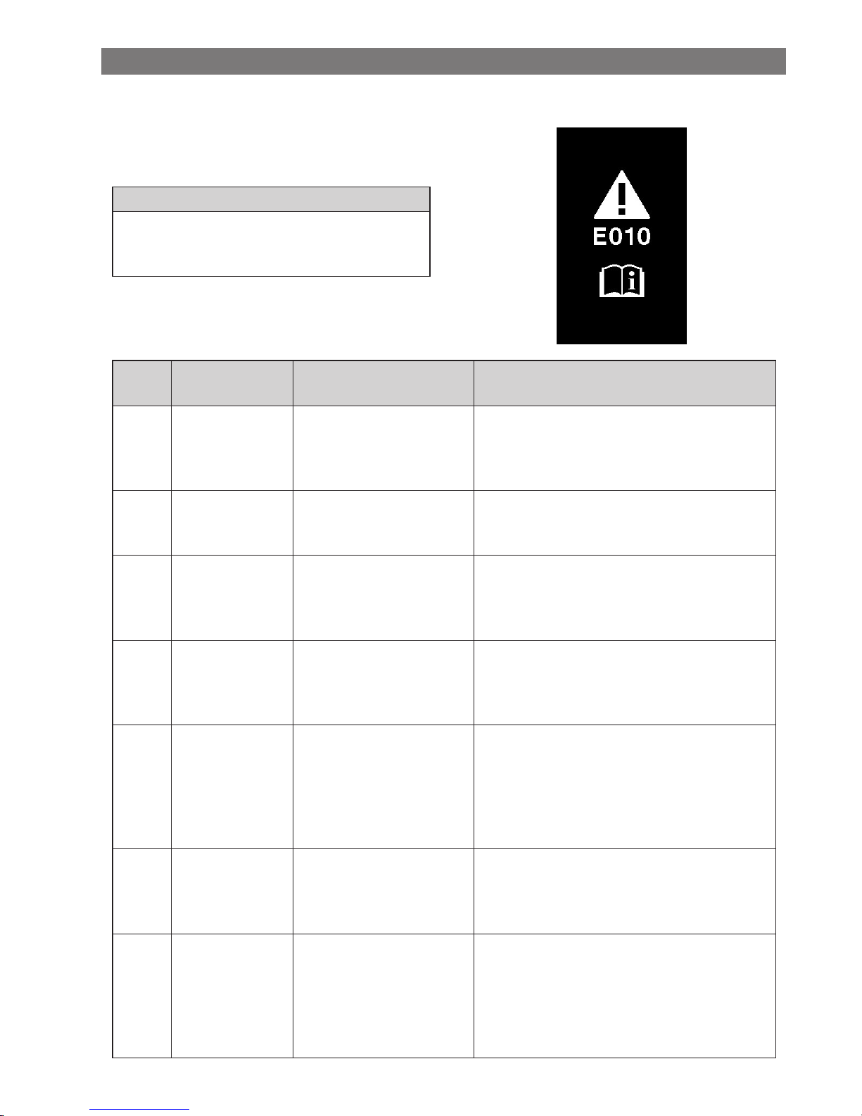
Error
If an error message is displayed on the entire screen,
follow one of the procedures below to reset the display.
•
Press the power button of the battery.
•
Remove the battery from the battery mount.
NOTE
If resetting the battery power does not solve the problem or
the same problem occurs frequently, contact the place of
purchase.
<SC-E6100>
Code
Display
preconditions
Operational restriction when
an error is being displayed
Remedy
E010
A system error was
detected.
Power assistance is not
provided during riding.
Press the power button of the battery to turn it on
again.
If the situation does not improve, contact the place
of purchase.
E013
An anomaly was
detected in the drive
unit’s firmware.
Power assistance is not
provided during riding.
Contact the place of purchase or bicycle dealer.
E014
The speed sensor
may have been
installed in the
wrong position.
Power assistance is not
provided during riding.
Contact the place of purchase or bicycle dealer.
E020
A communication
error between the
battery and drive
unit was detected.
Power assistance is not
provided during riding.
Check that the cable between the drive unit and
battery is properly connected.
If the situation does not improve, contact the place
of purchase.
E021
Battery connected
to drive unit
conforms with
system standards
but is not
supported.
Power assistance is not
provided during riding.
Contact your place of purchase or a local bicycle
dealer for assistance.
E022
Battery connected
to drive unit does
not conform with
system standards.
Power assistance is not
provided during riding.
Contact your place of purchase or a local bicycle
dealer for assistance.
E030
The installed
shifting component
differs from the
component
configured in the
system.
Power assistance is not
provided during riding.
Contact your place of purchase or a local bicycle
dealer for assistance.
Page 56
54
Code
Display
preconditions
Operational restriction when
an error is being displayed
Remedy
E033
The current
firmware is not
compatible with
this system.
Power assistance is not
provided during riding.
Connect to E-TUBE PROJECT, then update the
firmware for all units to the latest version.
E043
Part of the cycle
computer’s
firmware may be
damaged.
Power assistance is not
provided during riding.
Contact the place of purchase or bicycle dealer.
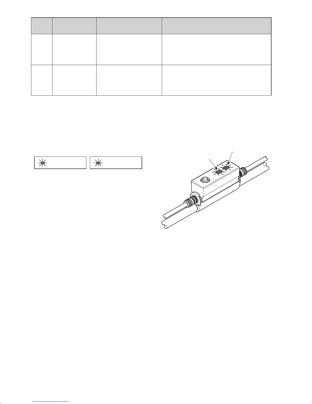
Error indications (EW-EN100)
If an error occurs, both LEDs of the EW-EN100 blink rapidly at the same time as shown below.
LED lamps indications
Inner side Outer side
Blinks fast in red Blinks fast in red
If the above occurs, immediately turn off the power then
consult the place of purchase or a bicycle dealer.
LED lamp
(outer side)
LED lamp
(inner side)
Page 57

55
Troubleshooting
Assist function
Symptom Cause / Possibility Remedy
Assistance is not being
provided.
Is the battery sufficiently charged?
Check the battery charge. If the battery is
nearly spent, recharge it.
Are you riding on long slopes in summer
weather or riding for a long time carrying a
heavy load?
The battery may be overheating.
Turn of
f the power, wait for a while and
then check once more.
The drive unit (DU-E6100/DU-E6110), cycle
computer (SC-E6100) or assist switch
(SW-E6010) may be connected incorrectly or
there may be a problem with one or more
of them.
Contact the place of purchase.
Is the speed too high?
Check the Cycle Computer display.
Assistance is not provided at speeds of
25 km/h or more.
Assistance is not being
provided.
Are you pedaling?
The bicycle is not a motorbike, so you need
to operate the pedals.
Is the assist mode set to [OFF]?
Set the assist mode to [HIGH]. If you still do
not feel that assistance is being given,
contact the place of purchase.
Is the system power ON?
If you have performed the steps below and
still do not feel the assistance, contact the
place of purchase.
Press and hold the cycle computer power
button for 2 seconds, or press the battery
power button to turn the power ON.
Assist traveling distance is
too short.
The traveling distance may become shorter
depending on road conditions, the gear
position and whether the light are ON or OFF.
Check the battery charge. If the battery is
nearly spent, recharge it.
The battery characteristics will drop during
winter weather.
This is not a sign of a problem.
The battery is a consumable part. Repeated
recharging and long periods of use will
cause the battery to deteriorate (lose its
performance).
If the distance that can be traveled on a
single charge is very short, replace the
battery with a new one.
Page 58

56
Symptom Cause / Possibility Remedy
Pedaling is stiff.
Are the tires inflated to a sufficient pressure?
Use a pump to add air.
Is the assist mode set to [OFF]?
Set the assist mode to [HIGH]. If you still do
not feel that assistance is being given,
contact the place of purchase.
The battery may be running low.
After charging the battery well, check the
level of assistance again. If you still do not
feel that assistance is being given, contact
the place of purchase.
Did you turn on the power with your foot
placed on the pedal?
Turn on the power again without putting
pressure on the pedal. If you still do not
feel that assistance is being given, contact
the place of purchase.
Battery
Symptom Cause / Possibility Remedy
All the five battery level
indicators stay on.
The firmware version of the drive unit may
be out-of-date.
Consult the place of purchase and check
the firmware version.
The battery quickly loses its
charge.
The battery may be at the end of its service
life.
Replace the battery with a new one.
The battery cannot be
recharged.
Is the power plug of the charger securely
inserted into the electrical outlet?
Disconnect and then reconnect the power
plug of the charger, and then repeat the
recharging operation.
If the battery still cannot be recharged,
contact the place of purchase.
Is the recharging plug of the charger
securely inserted into the battery?
Disconnect and then reconnect the
recharging plug of the charger, and then
repeat the recharging operation.
If the battery still cannot be recharged,
contact the place of purchase.
Is the charging adapter securely connected
to the charging plug, or to the battery
charging port?
Securely connect the charging adapter to
the charging plug or to the battery
charging port, and charge again. If the
battery still does not charge, consult a
dealer.
Is the connecting terminal for the battery
charger, charging adapter, or battery dirty?
Wipe the connection terminals with a dry
cloth to clean them, and then repeat the
recharging operation.
If the battery still cannot be recharged,
contact the place of purchase.
The battery does not start
recharging when the
charger is connected.
The battery may be at the end of its service
life.
Replace the battery with a new one.
The battery and charger are
becoming hot.
The temperature of the battery or charger
may exceed the operating temperature
range.
Stop recharging, wait for a while and then
recharge again. If the battery is too hot to
touch, it may indicate a problem with the
battery. Contact the place of purchase.
Page 59

57
Symptom Cause / Possibility Remedy
The charger is warm.
If the charger is being used continuously to
charge batteries, it may become warm.
Wait a while before using the charger
again.
The LED on the charger
does not illuminate.
Is the recharging plug of the charger
securely inserted into the battery?
Check the connection for any foreign
objects before reinserting the charging
connector. If there is no change, contact
the place of purchase.
Is the battery fully charged?
If the battery is fully charged, the LED on
the battery charger turns off, but this is not
a malfunction. Disconnect and then
reconnect the power plug of the charger,
and then repeat the recharging operation.
If the LED on the charger still does not
illuminate, contact the place of purchase.
The battery cannot be
removed.
Contact the place of purchase.
The battery cannot be
inserted.
Contact the place of purchase.
Fluid is coming out from the
battery.
Contact the place of purchase.
An abnormal odor can be
detected.
Stop using the battery immediately and
contact the place of purchase.
Smoke is coming out from
the battery.
Stop using the battery immediately and
contact the place of purchase.
The replaced battery does
not work.
The firmware of the drive unit may not be
compatible with the battery.
Contact the place of purchase to inquire
about compatibility.
Lights
Symptom Cause / Possibility Remedy
The front light or the tail
light does not illuminate
even when the switch is
pressed.
The E-TUBE PROJECT settings may be
wrong.
Contact the place of purchase.
Page 60

58
Cycle computer
Symptom Cause / Possibility Remedy
The cycle computer is not
displayed when you push
the battery power button.
The amount of battery charge may be
insufficient.
Recharge the battery, and then turn the
power on once more.
Is the power turned on?
Hold down the power button to turn on
the power.
Is the battery charging?
The power cannot be turned on while the
battery is mounted on the bicycle and
being charged. Stop charging.
Is the cycle computer correctly installed to
the bracket?
Install the cycle computer correctly while
referring to "Installing and removing the
cycle computer".
Is the electric wire connector correctly
installed?
Check to see if the connector of the electric
wire connecting the motor unit to drive
unit is not disconnected. If you are not
sure, contact the place of purchase.
A component that the system cannot
identify may be connected.
Contact the place of purchase.
The system does not start
up when you press and hold
the cycle computer power
button for 2 seconds.
Did you use the cycle computer in, or
expose it to, low temperatures for an
extended period?
The cycle computer may become unable to turn
on if used in, or exposed to, low temperatures
for an extended period. Turn it on by pressing
the power button on the battery. If it still does
not turn on, consult a dealer.
Is the cycle computer correctly installed to
the bracket?
Install the cycle computer correctly while
referring to "Installing and removing the
cycle computer".
The gear position is not
displayed.
The gear position is only displayed when
the electronic gear shifting unit is installed.
Check if the electric wire connector is
disconnected. If you are not sure, contact
the place of purchase.
Can the beep be turned off.
Change the setting.
Refer to "Beep".
Can the backlight be turned
off.
Change the setting.
Refer to "Backlight".
The setting menu cannot be
launched while riding the
bicycle.
The product is designed so that if it detects
that the bicycle is being ridden, the Setting
menu cannot be launched. This is not a sign
of an abnormality.
Stop the bicycle and then make the
settings.
Page 61

59
Other
Symptom Cause / Possibility Remedy
When pressing the switch,
two beeps sound, and the
switch cannot be operated.
Operation of the switch being pressed has
been disabled.
It is not a sign of a malfunction.
Three beeps sound. An error or warning is occurring.
This occurs when a warning or error is
displayed on the cycle computer. Refer to
the section "Error messages on the cycle
computer" and follow the instructions
provided for the appropriate code.
When using a electronic gear
shifting mode, I feel that the
level of assistance weakens
when the gears shift.
This occurs because the level of assistance is
being adjusted to the optimum level by the
computer control.
It is not a sign of a malfunction.
Sound occurs after gear
shifting.
Contact the place of purchase.
A noise can be heard from
the rear wheel during
normal riding.
Gear shifting adjustment may not have
been carried out correctly.
For mechanical gear shifting
Adjust the cable tension. For details, refer
to the Service Instructions for the derailleur.
For powered gear shifting
Contact the place of purchase.
When you stop the bicycle,
the gear does not shift to
the position preset in the
start mode.
You may have been pressing the pedals too
strongly.
If you press the pedals lightly, the gear
shifts more easily.
Page 62
*
Key number
The number that is attached to the key is needed in case you need to purchase spare keys.
Make a note of the number in the following box and keep it in a safe place.
Key number
Please note: specifications are subject to change for improvement without notice. (English)
© Mar. 2018 by Shimano Inc. ITP
 Loading...