

Page 1

ROWING
SRD Footstretcher Assembling Manual
g
Shimano,Inc
© 2009 Shimano, Inc. ALL RIGHTS RESERVED
1
Page 2
ROWING
Index
■ Getting started
(1) Check contents in the box ………………………………...………P3
(2)
Genuine Boat Parts Applied to SRD ……………………..………P4
()
pp
(3) Tools …………………………………………………………………P5
■ Installing and Adjusting
(4) Installing Attachment Pipe …………………………………………P6
(5) Installing the Upper Pipe ……………………………………………P7
(6) Temporary Assemble ………………………………………….……P8
(7) Adjusting the Footstretcher Angle …………………………………P9
(8)
Checki
ng the Space …………………………………………………
P10
(9) Adjusting the Stance …………………..…………………………….P11
(10) Fixing the Frame Unit ………………………..…………………….P12
(11) Adjusting the Height of the Binding Units ……….……………….P13
(12) Adjusting the position of the SRD Footstretcher System ………P14
(12) -1/2/3 How you can measure the position …....………………….P15
(14) Adjusting the Heel Plates …....…………………………..………. P17
(15) Adjusting the Step-in Position …....…………………..…………. P18
(16) Adjusting the Binding Tension …....…………………………..…. P19
(17)
Installing the Cleats
…....………………………………………….
P20
(18) Adjusting the position of the Cleats …............…………………. P21
■Note
© 2009 Shimano, Inc. ALL RIGHTS RESERVED
2
NOTE
…....……………………………………………………………….
P23
Page 3
ROWING
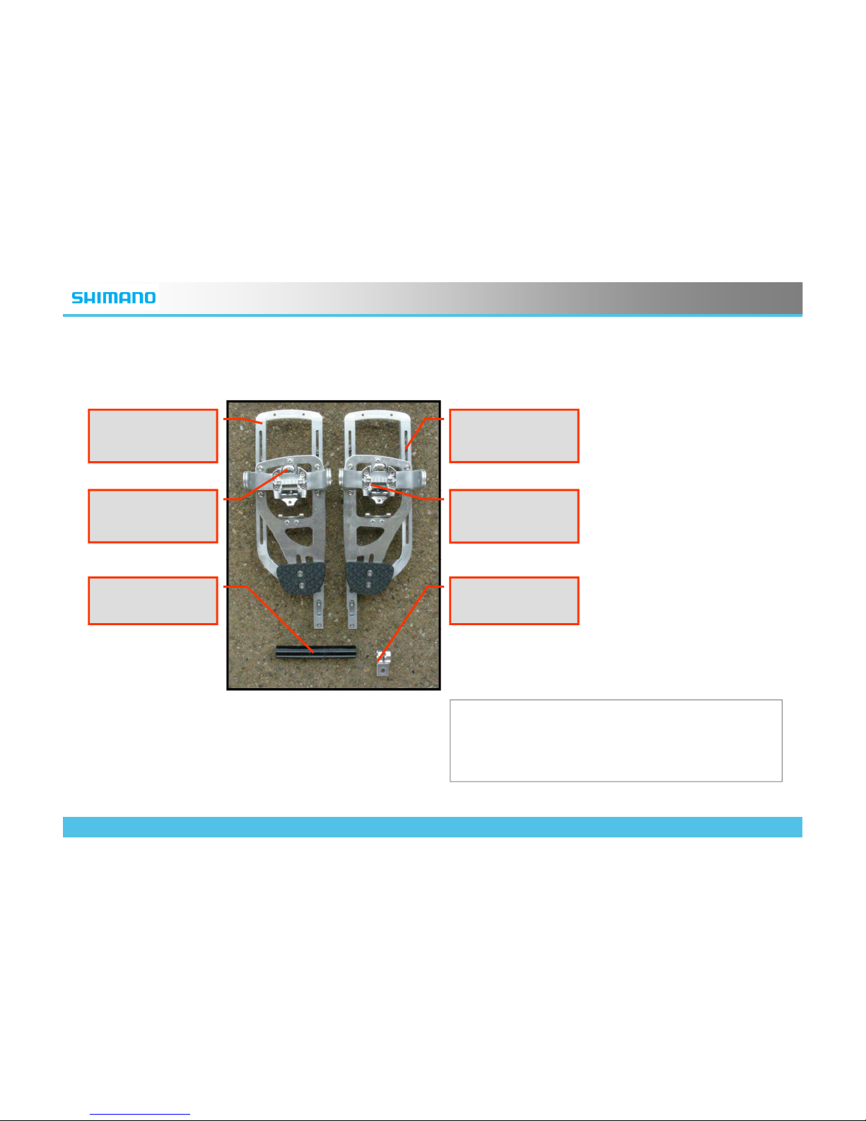
(1) Check contents in the box
F
rame Un
it
(right)
F
rame Un
it
(left)
Binding Unit
(right)
Binding Unit
(left)
KF-R600
Attachment Pipe
Lower Fitting
• These are all in the package.
• Binding units are fixed on the Frame Units in
the package.
© 2009 Shimano, Inc. ALL RIGHTS RESERVED
3
Page 4
ROWING
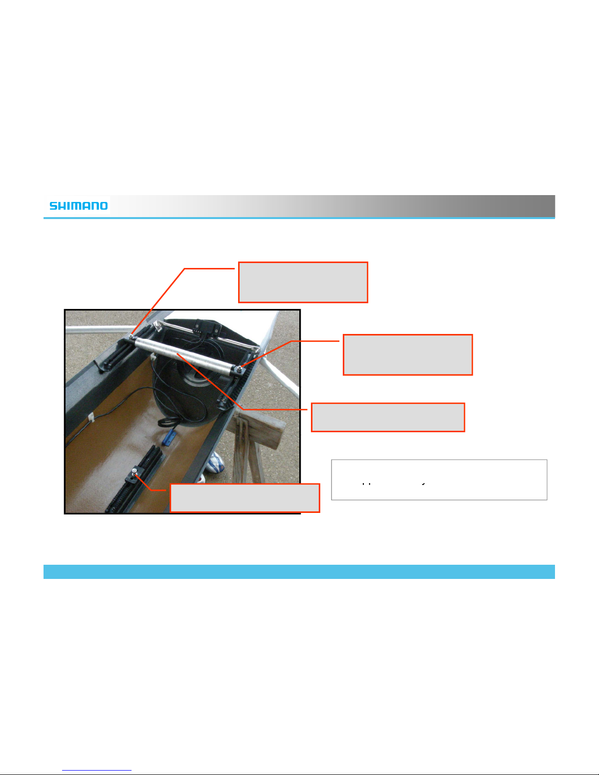
(2) Genuine Boat Parts Applied to SRD
Upper Pipe
Mounting(left)
Upper Pipe
Mounting(right)
Upper Pipe(25mm φ)
• These genuine parts should be
a
pp
lied from your boat to mount
pp y
SRD Footstretcher.
Lower Mounting
© 2009 Shimano, Inc. ALL RIGHTS RESERVED
4
Page 5
ROWING
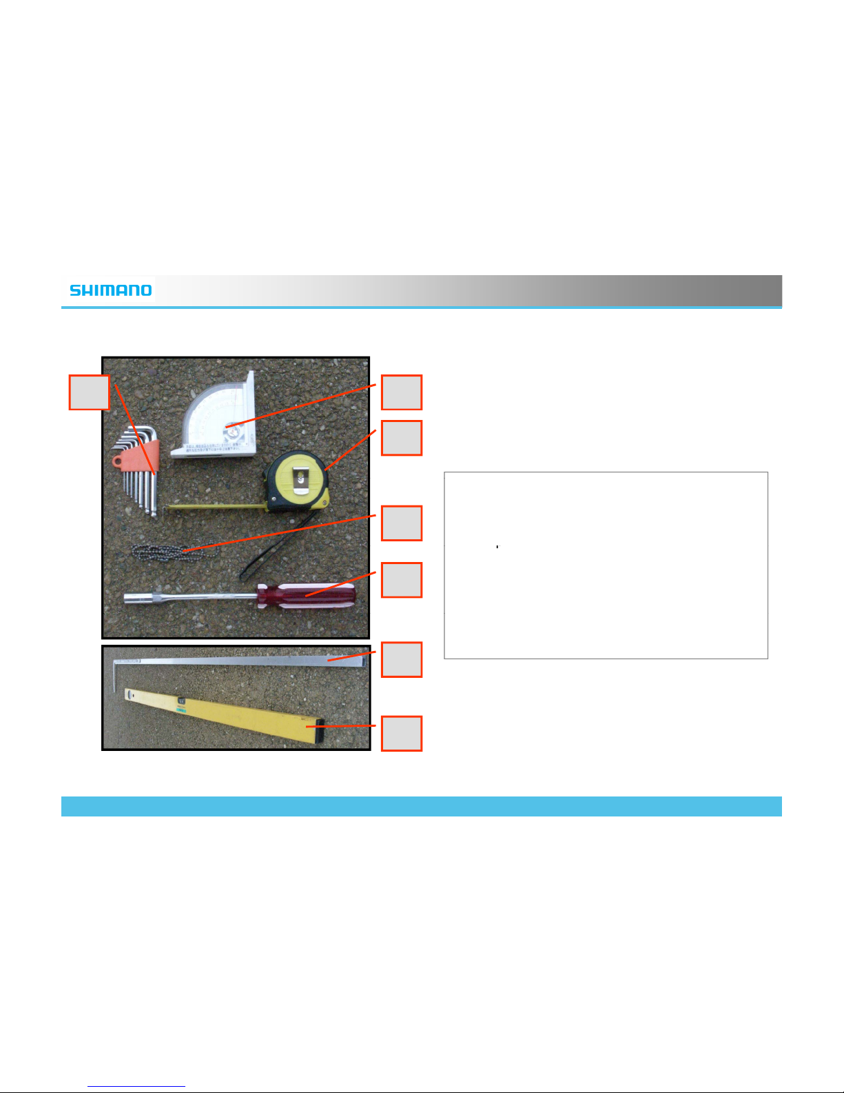
(3) Tools
A B
C
D
A:Hexagon Wrenches(3mm will be used
mainly)
B:Angle Meter
C:Ta
p
e Measure
E
p
D:String
E:Tool(s) each boat manufacturer recommend
to fix the Footstretcher system. In this photo
10mm Wrench is shown.
F
F
:Long Aluminum Rectangle Pipe
G:Level
G
© 2009 Shimano, Inc. ALL RIGHTS RESERVED
5
Page 6
ROWING
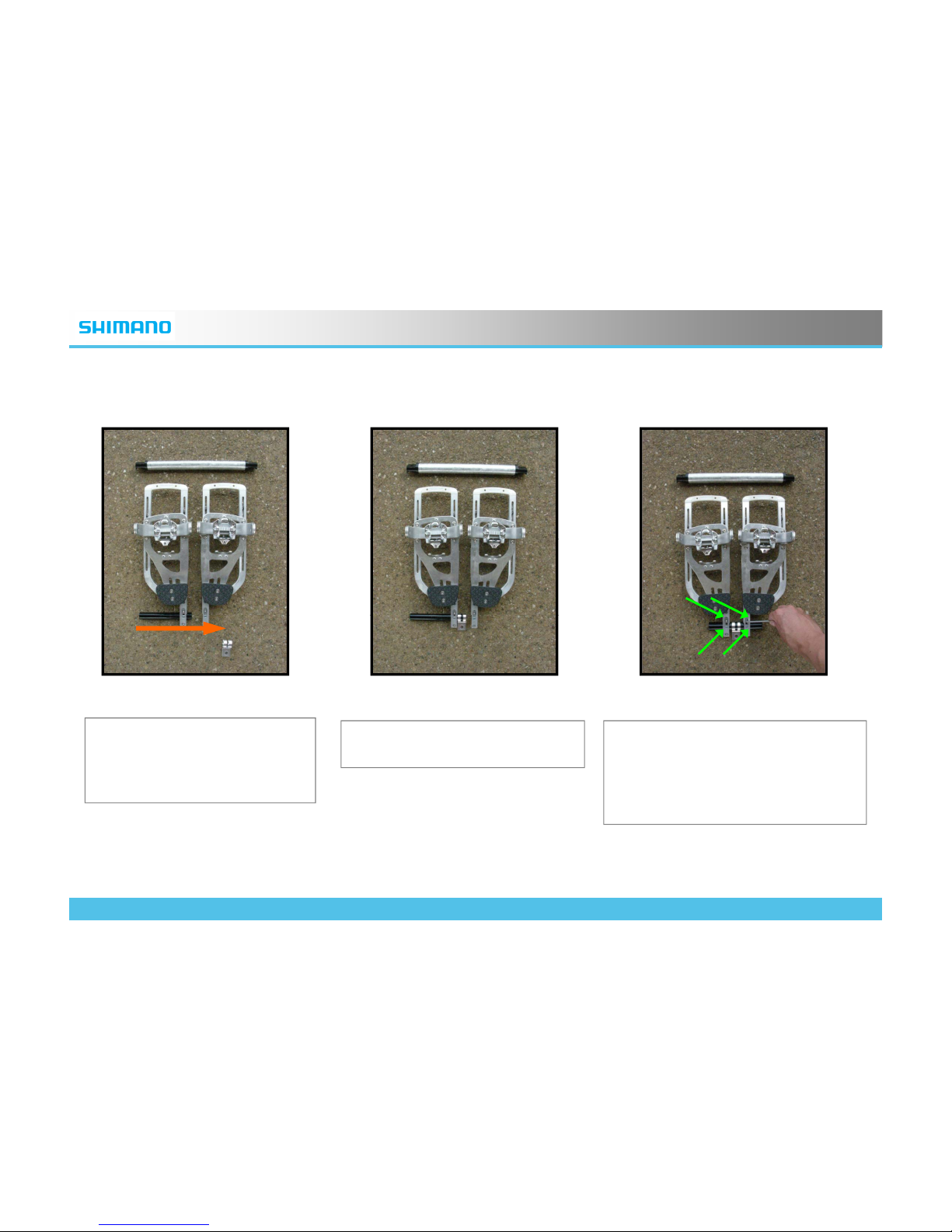
(4) Installing Attachment Pipe
・Loosen up 4 bolts fixing the
Lower Pipe.
・Put the Lower Fitting part on
the Lower Pipe
・Let the Lower Pipe go through the
metal fitting cramps, then tighten
・Install the Lower Pipe.
t
emporarily. (You do not have to
tighten these firmly before the
procedure (6) )
© 2009 Shimano, Inc. ALL RIGHTS RESERVED
6
Page 7
ROWING
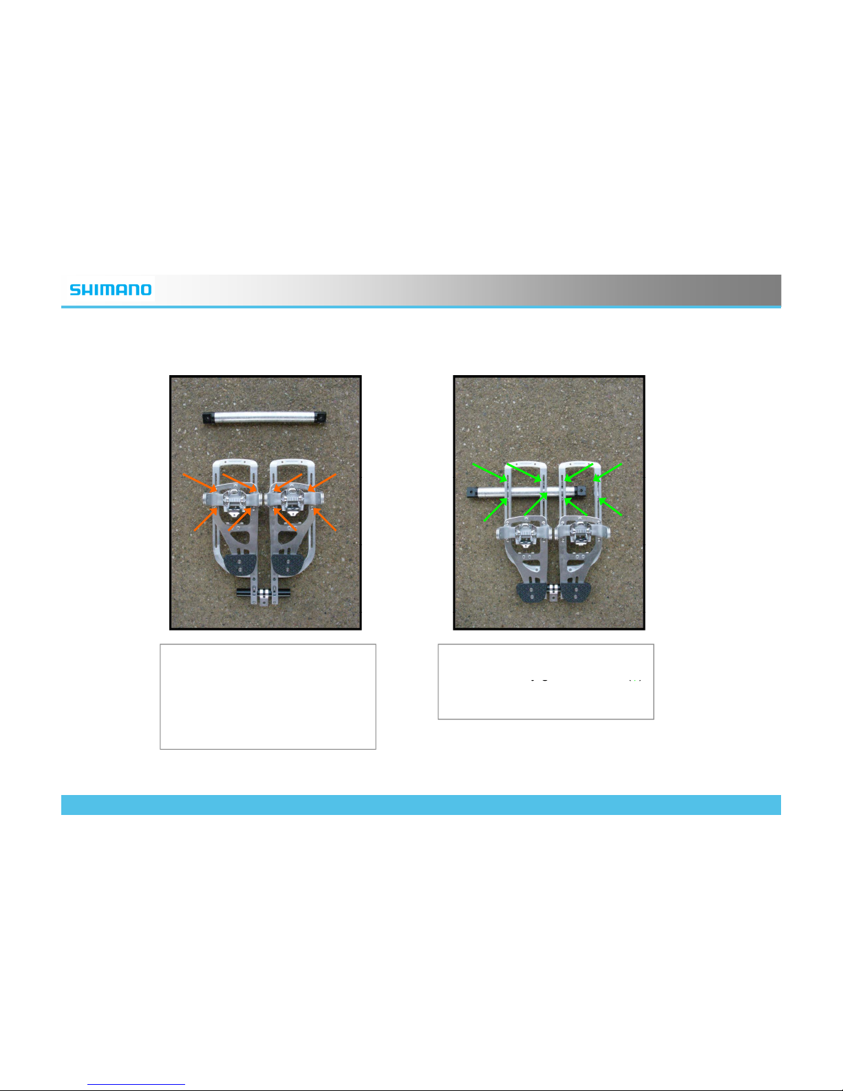
(5) Installing the Upper Pipe
Procedure (5) -1: Loosen the
bolts shown by orange arrows
Procedure (5) -2: Loosen the
bolts shown b
y g
reen arrows
(
↑
)
(↑)and slide down the Binding
Unit. With this operation it will
be easier to manipulate the
Upper Pipe.
yg (
↑
)
and install the upper pipe.
© 2009 Shimano, Inc. ALL RIGHTS RESERVED
7
Page 8
ROWING
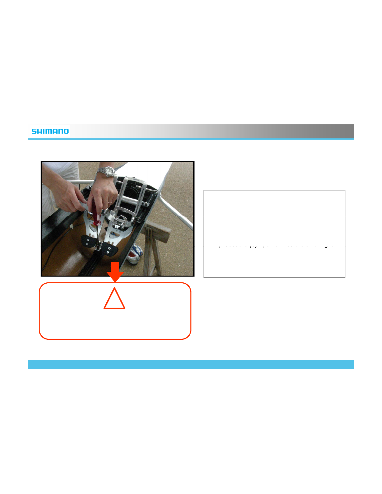
(6) Temporary Assemble
• Put your SRD Footstretcher on the boat by
using tools the boat manufacturer
recommends.
• CAUTION: Do not too much loosen the
bolts on the Binding Units shown on
procedure
(5)-1, othe
rwise the unit might
p ocedu e
(5)
,ote seteu t gt
slide down on the Frame Unit and result in
damaging the hull.
!
CAUTION:
DO NOT let the Binding Units slide down
© 2009 Shimano, Inc. ALL RIGHTS RESERVED
8
Page 9
ROWING
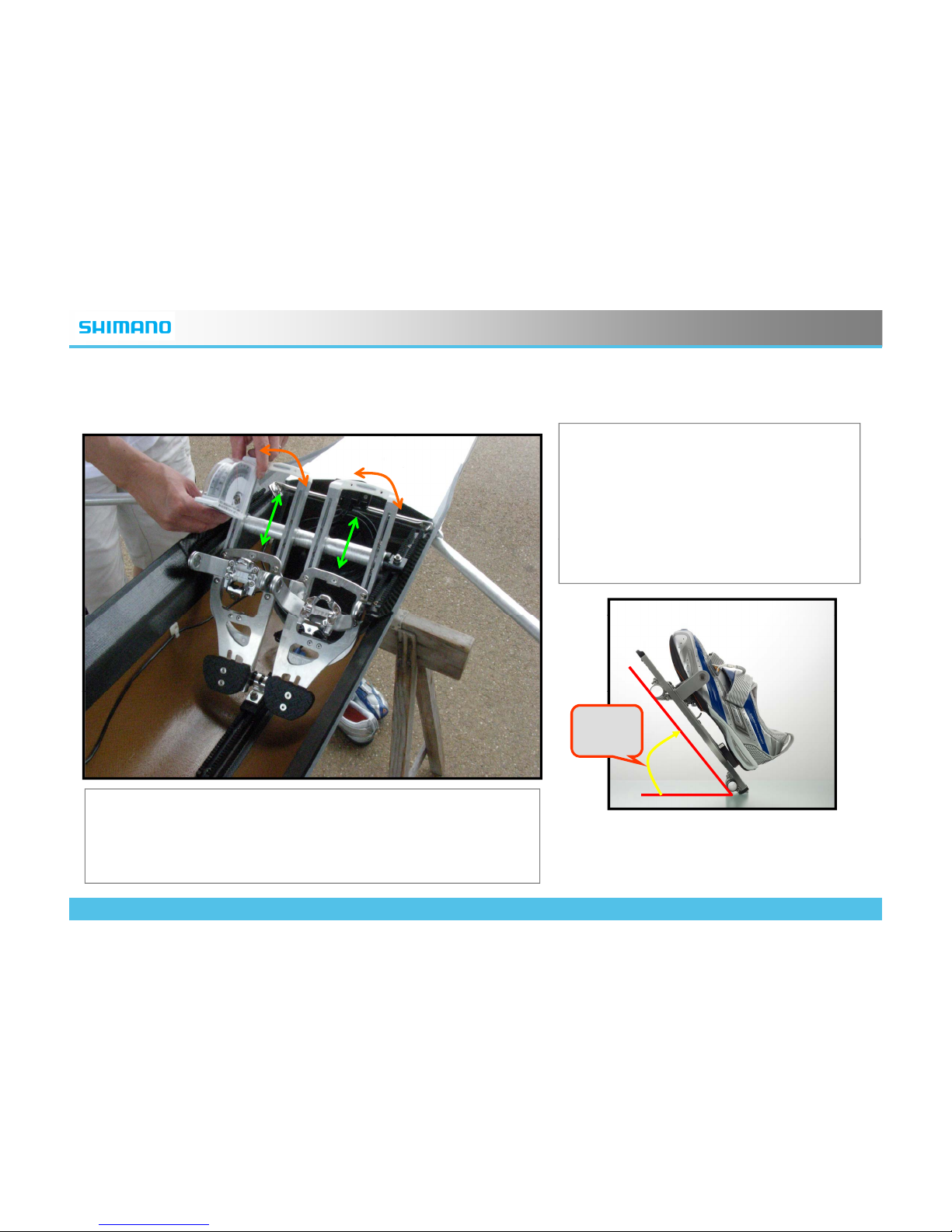
(7) Adjusting the Footstretcher Angle
• Adjust the angle of SRD
Footstretcher system by sliding the
upper pipe up and down.
• The standard setting of the angle is
50 degrees up from horizontal.
• You can check it by applying the
angle meter on the Frame Unit.
50°
*All the bolts on Footstretcher system has to be fastened when
you try to check the precise angle, otherwise the
© 2009 Shimano, Inc. ALL RIGHTS RESERVED
9
measurements will be inaccurate
.
Page 10
ROWING
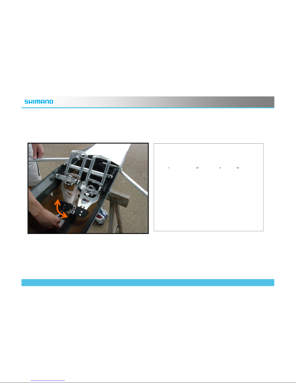
(8) Checking the Space
• Allow 1CM space between the edge of the
SRD Footstretcher system and the inside of
the hull. It is easier to check whether the
s
p
ace is enough or not by moving a small
pgyg
stick such as a pencil around the
Footstretcher.
• CAUTION: To avoid the damage to the hull,
this space must be there. The Footstretcher
system sags slightly when strong force is
applied on it.
• If the lower end of the Frame Units are
hitting the hull, change the position of the
lower pipe fitting cramps.
© 2009 Shimano, Inc. ALL RIGHTS RESERVED
10
Page 11
ROWING
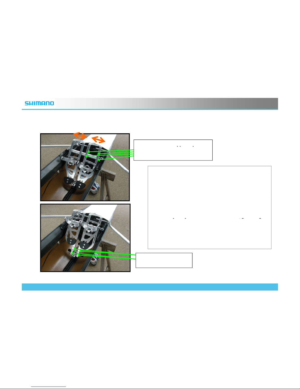
(9) Adjusting the Stance
Bolts to hold the Upper Pipe
pp p
fitting cramps(Only bolts on right
unit is shown)
•
L
oosen the bolts shown by green arrows a
littl
e. You
can set the stance width by moving Frame Unit
sideways.
• You should slide the binding units up and down on
the Frame Unit to have the access to those bolts
.
CAUTION: Do not loosen those bolts too much,
otherwise the binding unit may slide down and hit
the hull to result in the serious damage to the hull.
• When you try to make the stance wider, go through
yy ,g g
procedure (8)again to make sure there is the enough
space.
• If you are setting SRD Footstretcher on the single
scull, we recommend to have the stance as wide as
the space against the hull allows
.
Bolts to hold the Lower
Pipe fitting cramps
© 2009 Shimano, Inc. ALL RIGHTS RESERVED
11
Page 12
ROWING
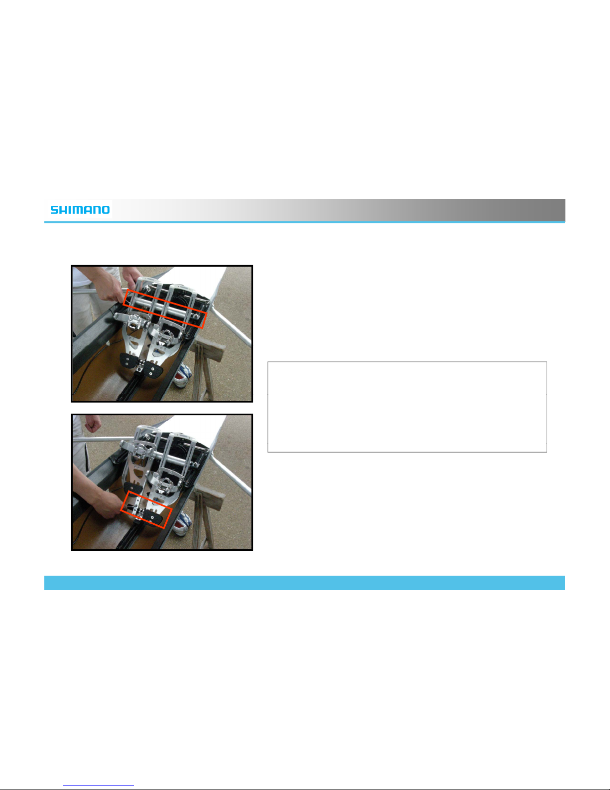
(10) Fixing the Frame Unit
• Fasten all the bolts to hold the upper and lower pipes
firmly.
• With this operation you will completely set the angle of
the SRD Footstretcher System. So check the
Footstrecher angle again as shown at procedure (7) .
© 2009 Shimano, Inc. ALL RIGHTS RESERVED
12
Page 13
ROWING
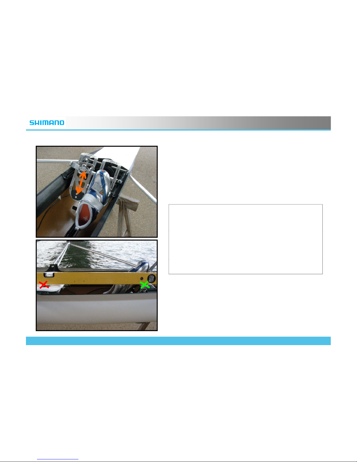
(11) Adjusting the Height of the Binding Units
• Slide the Binding Units on the Frame Units to
set the height.
•
The height of th
e center of the Virtual Pivot
axis(X) should be 0-3CM lower than the
height of the seat. The lowest point of the top
surface ,usually edge of the holes (X), should
b
e measured to check the height of the seat.
© 2009 Shimano, Inc. ALL RIGHTS RESERVED
13
Page 14
ROWING
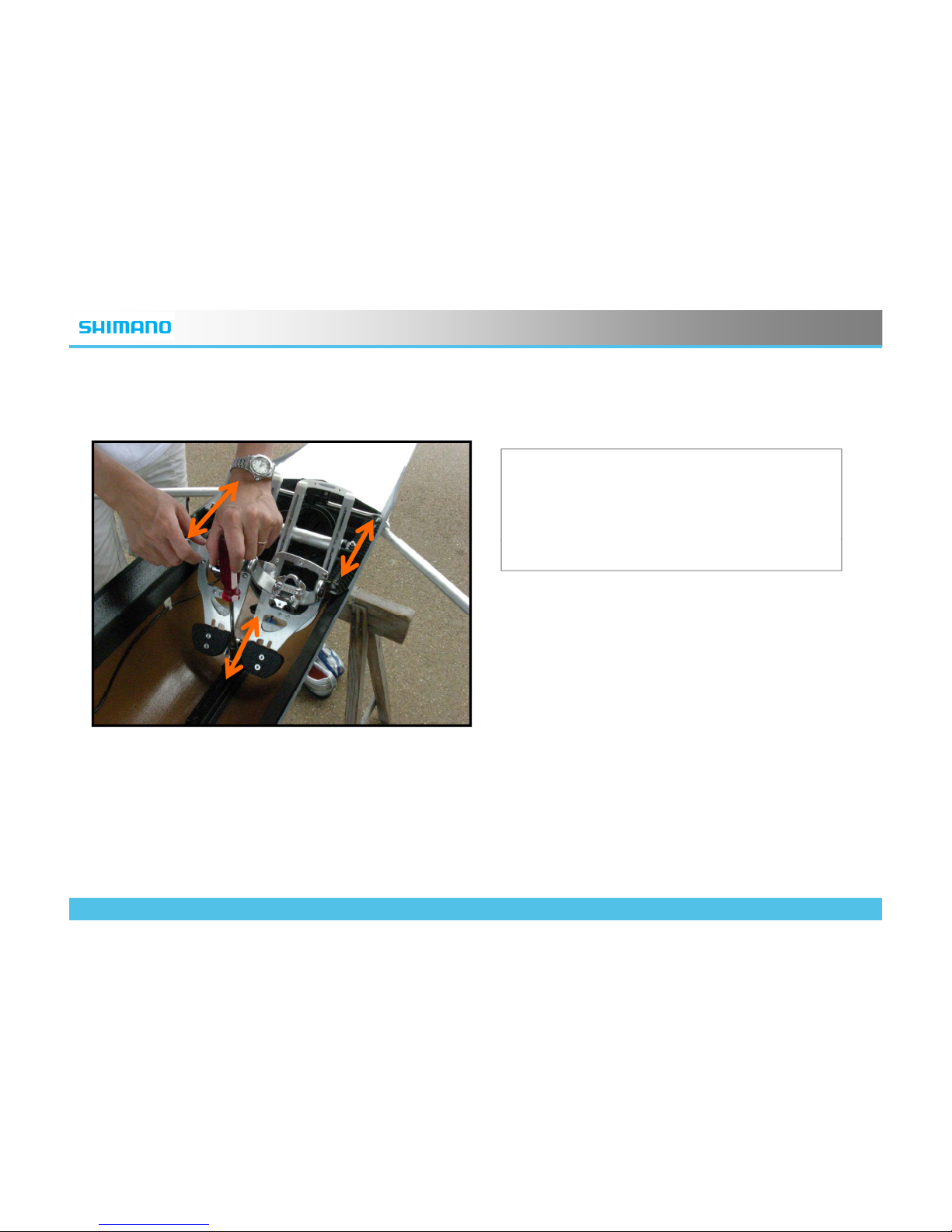
(12) Adjusting the position of the SRD Footstretcher System
• Loosen the 3 mounting bolts and adjust
the position of the Footstretcher System
by sliding forward and backward on the
gear rails
.
© 2009 Shimano, Inc. ALL RIGHTS RESERVED
14
Page 15
ROWING
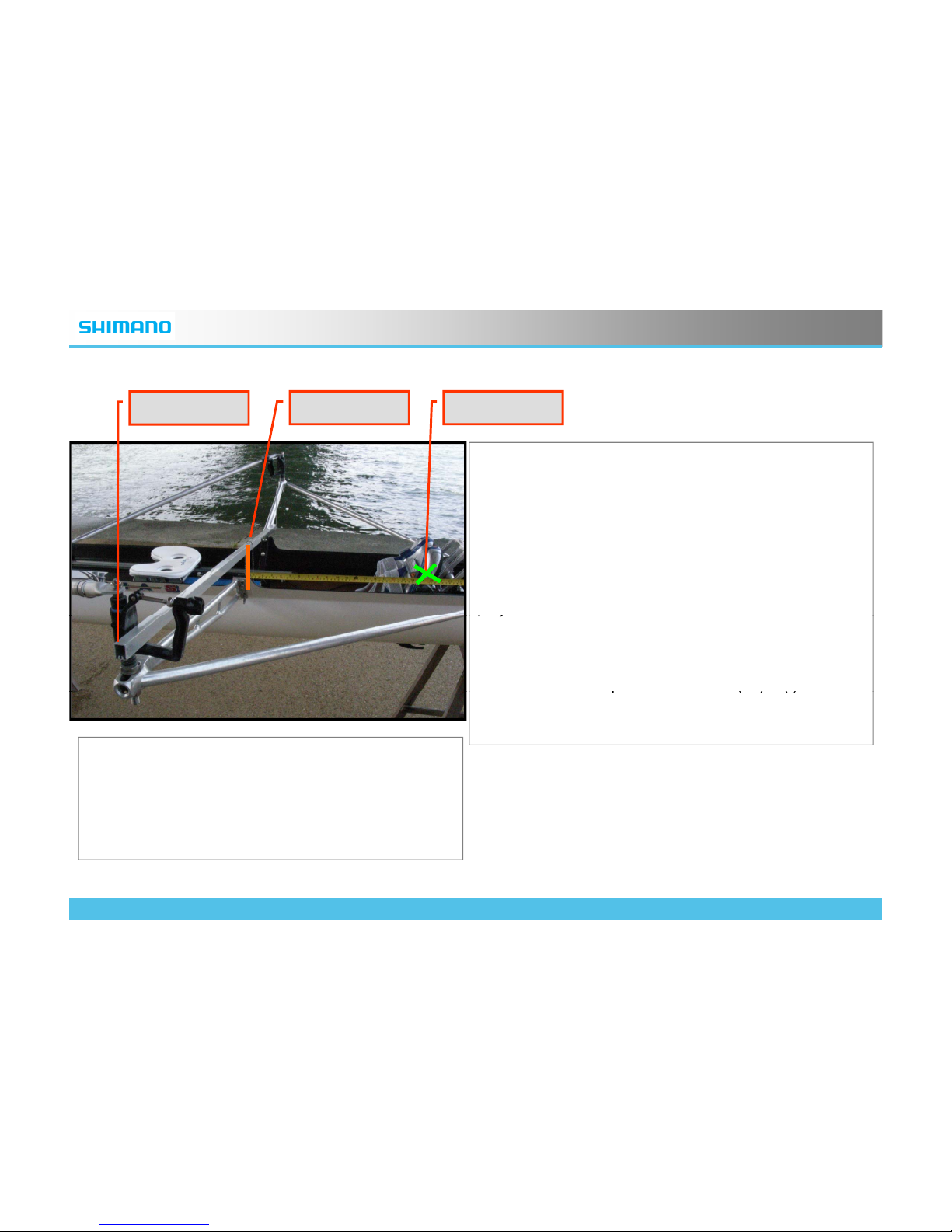
(12) -1/2/3 How you can measure the position
(12)-1
(12)-2 (12)-3
Step (12)-1:Attach the long straight aluminum
rectangle pipe on the work face of the oarlock, and
make it orthogonal to the center line (or keel line) of the
boat.
Step (12)-2:Hang the string on the pipe. This string
represents the horizontal position of the work face
proj
ected on the center line.
pj
Step (12)-3:Put a tape measure or a ruler horizontally,
and parallel to the center line. Measure the distance
from the work face
p
osition shown in (12)-2 (I) to the
p()
(
)
center of the axis of Virtual Pivot (X).
*The positioning of the root of the thumbs on soles
should be the same in both conventional
Footstretcher and the SRD System.
*The Boat should be laid on the slings in completely
© 2009 Shimano, Inc. ALL RIGHTS RESERVED
15
horizontal way
.
Page 16
ROWING
(13) Setting it right
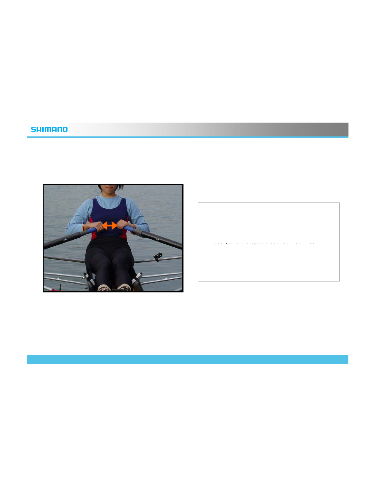
• To set Footstretchers on appropriate
pos
iti
on, the easiest way is to get on the
boat. Stop at the finish position.
• This picture shows an example of a sculling
boat, and the space between both oar
handle should be 1-2 fists.
• If this space is too much open, move the
Footstretcher system toward the stern. If
too narrow, toward the bow
.
© 2009 Shimano, Inc. ALL RIGHTS RESERVED
16
Page 17
ROWING
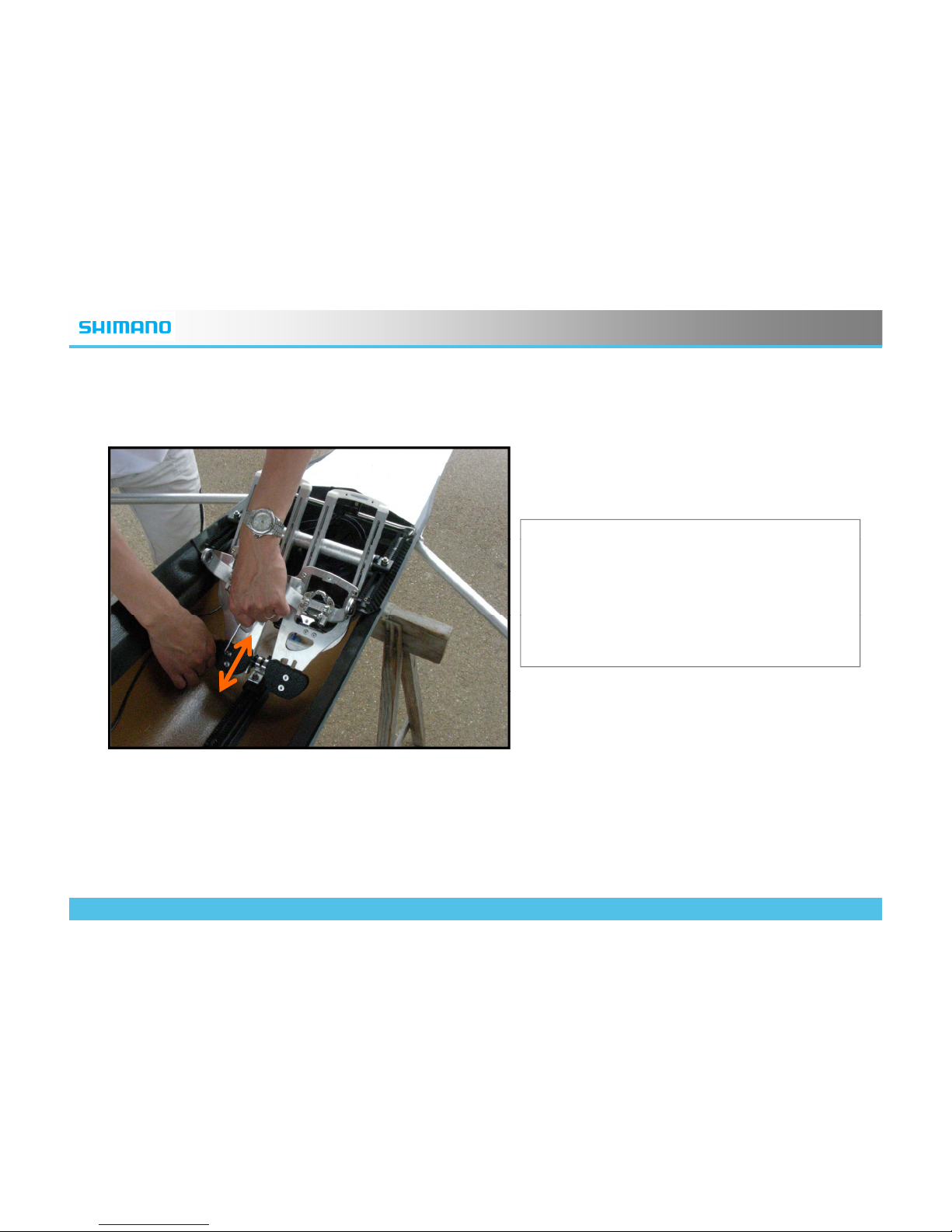
(14) Adjusting the Heel Plates
• Loosen the bolt and slide the Heel Plates
up and down on the Binding Unit.
• This part is set to support the heel of the
shoes. Readjust to determine the best
position.
© 2009 Shimano, Inc. ALL RIGHTS RESERVED
17
Page 18
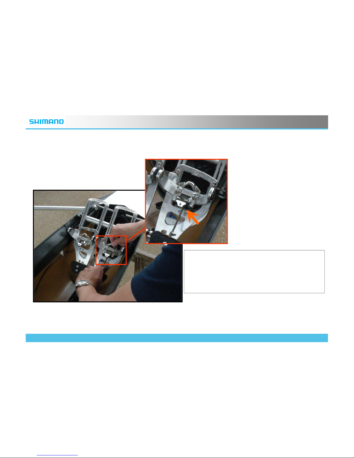
ROWING
(15) Adjusting the Step-in Position
• You can adjust the range of swinging
motion by the adjustment bolt which
locates on the reverse side of the swing
arm
.
© 2009 Shimano, Inc. ALL RIGHTS RESERVED
18
Page 19
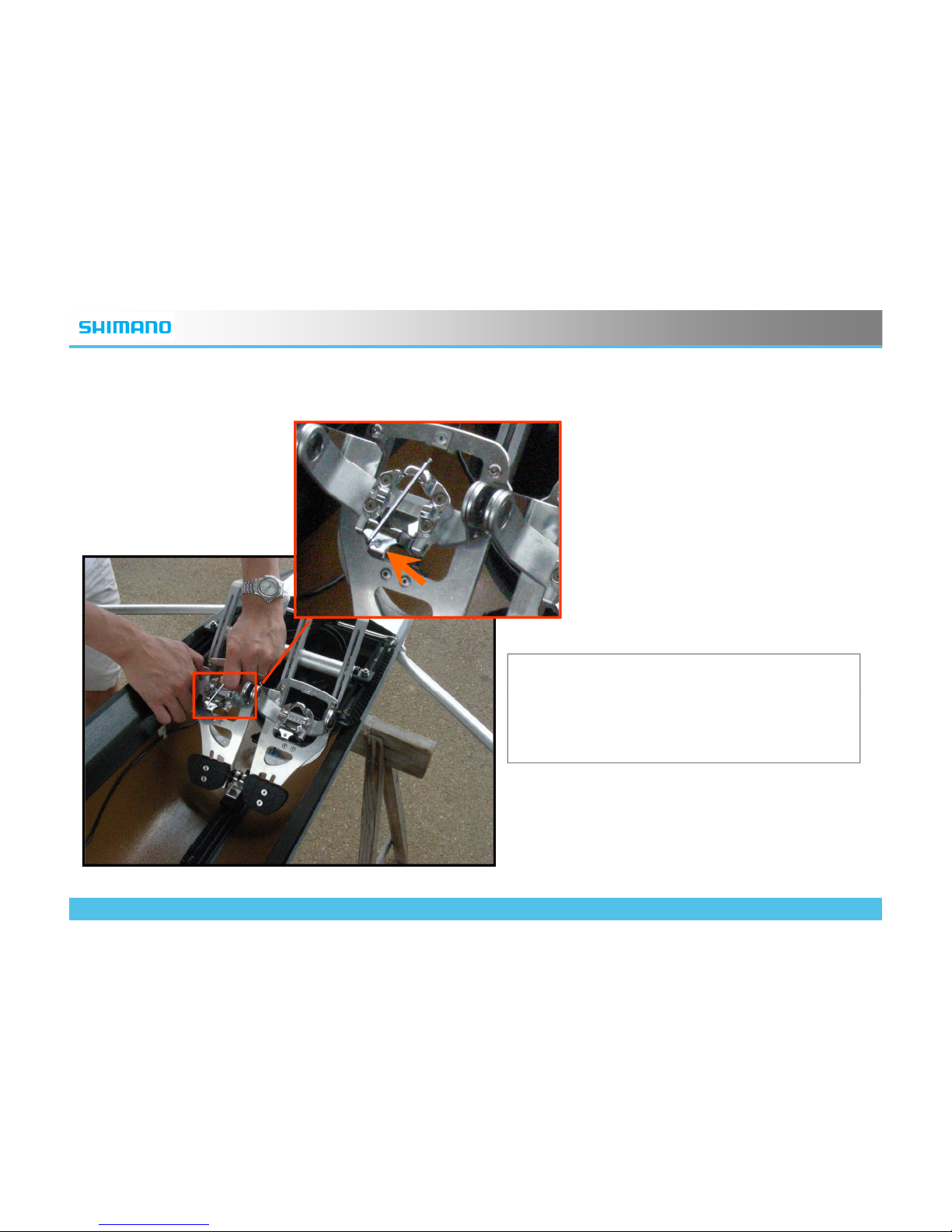
ROWING
(16) Adjusting the Binding Tension
•
You can adjust the Binding Tension by the
adjustment bolt which is shown with the
orange arrow.
© 2009 Shimano, Inc. ALL RIGHTS RESERVED
19
Page 20
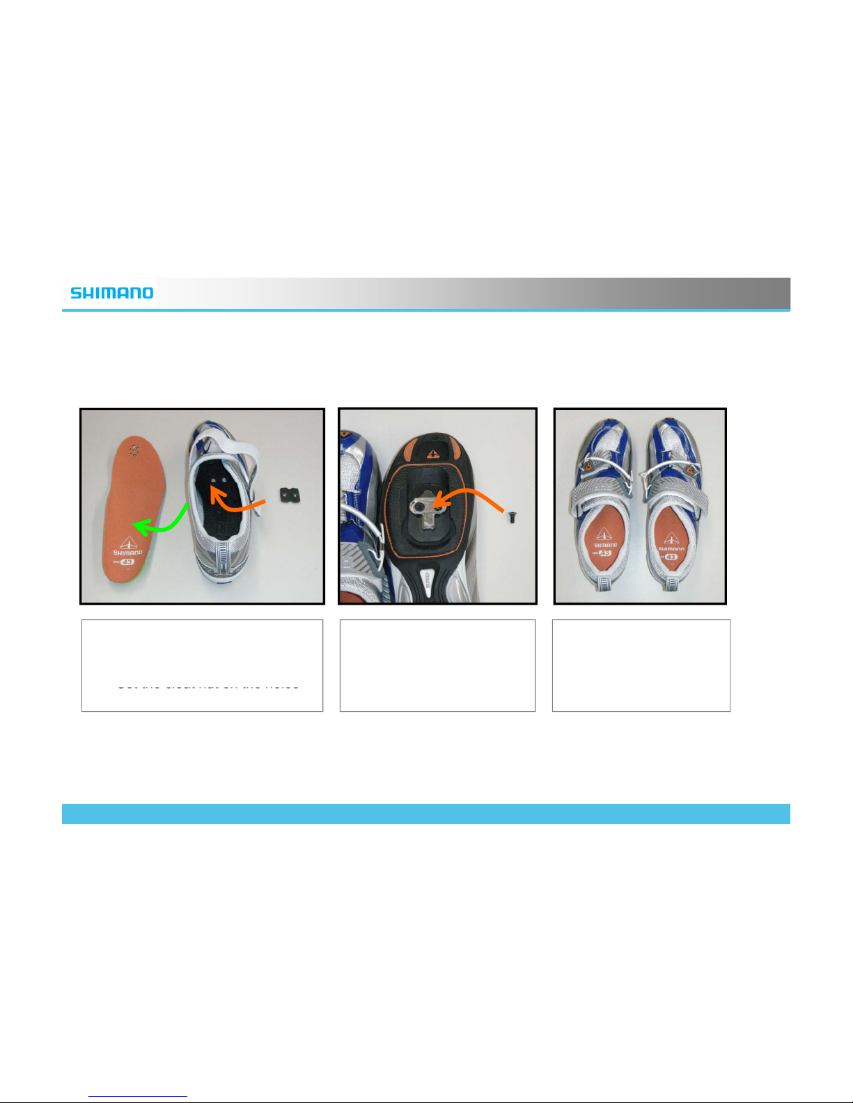
ROWING
(17) Installing the Cleats
• Open the uppers of the shoes
and put the sockliners off.
•
• Put the sockliners
into the shoes.
• Put the cleat, the
washer, and the bolts on
the bottom of the shoes.
Set the cleat nut on the holes
provided on the SRD shoes.
Th
en tighten the bolts.
© 2009 Shimano, Inc. ALL RIGHTS RESERVED
20
Page 21
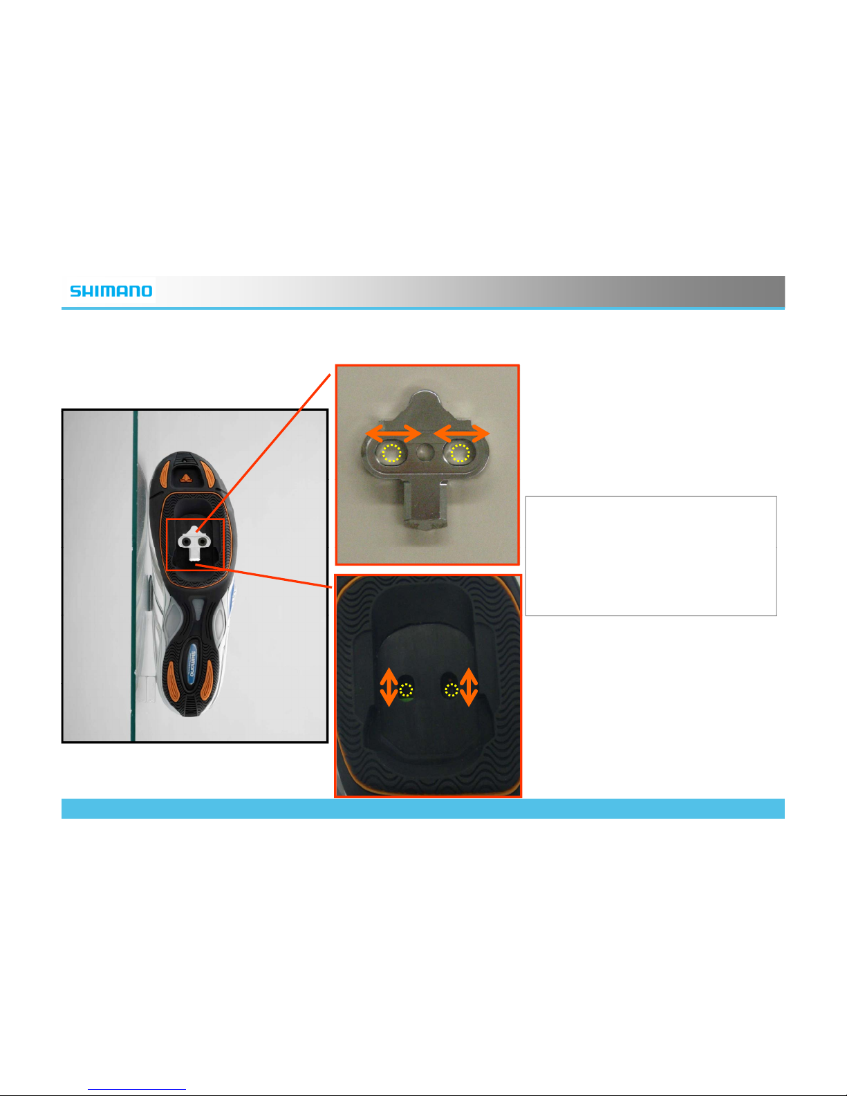
ROWING
(18) Adjusting the position of the Cleats
• You can adjust the position
of the Cleats by sliding along
the holes of the Cleats, and
the shoes.
© 2009 Shimano, Inc. ALL RIGHTS RESERVED
21
Page 22
ROWING
(18) Now you are ready
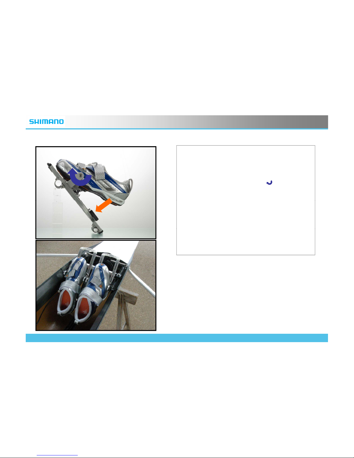
• Now your SRD Footstretcher system is ready
to go.
• When you get on the boat, hook the front of
the cleat on the binding first ( ) , then press
down on the heel plate(↓).
•
To release, lift the heels up or twist the feet
.
• For your safety, practice again and again to
engage and to release.
• You can readjust the system once in a while,
and enjoy the benefit of the SRD
Footstretcher system.
© 2009 Shimano, Inc. ALL RIGHTS RESERVED
22
Page 23

ROWING
NOTE
• The Systems photographed in this document are all prototypes, so the look and the spec is subject to be
changed without any notice.
• Use this document just as a reference when the SRD System is newly introduced. For your safety, read
carefully the technical service instruction attached with the products.
© 2009 Shimano, Inc. ALL RIGHTS RESERVED
23
 Loading...