

Page 1
One Holland, Irvine, California 92618, U.S.A. Phone: +1-949-951-5003
Industrieweg 24, 8071 CT Nunspeet, The Netherlands Phone: +31-341-272222
3-77 Oimatsu-cho, Sakai-ku, Sakai-shi, Osaka 590-8577, Japan
General Safety Information
• The 203 mm and 180 mm rotors provide a higher braking
force than the 160 mm rotors. Make sure that you have a
complete feel for the braking characteristics before using
the brakes.
• Please use extra caution to keep your fingers away from the rotating disc
brake rotor during installing or servicing the wheel. The rotor is sharp enough
to inflict severe injury to your fingers if caught within the openings of moving
rotor.
• The calipers and rotor will become hot when the brakes are operated, so do
not touch them while riding or immediately after dismounting from the bicycle,
otherwise you may get burned. Check that the brake components have cooled
down sufficiently before attempting to adjust the brakes.
• Always make sure that the front and rear brakes are working correctly before
you ride the bicycle.
• Be careful not to allow any oil or grease to get onto the rotor and brake pads,
otherwise the brakes may not work correctly.
• If the quick release lever is on the same side as the rotor, there is the danger
that it may interfere with the rotor, so check that it does not interfere.
• Obtain and read the service instructions carefully prior to installing the
parts. Loose, worn or damaged parts may cause the bicycle to fall over and
serious injury may occur as a result. We strongly recommend only using
genuine Shimano replacement parts.
• Read these Technical Service Instructions carefully, and keep them in a safe
place for later reference.
• Disc brakes have a burn-in period, and the braking force will gradually
increase as the burn-in period progresses. Make sure that you are aware of
any such increases in braking force when using the brakes during the burn-in
period. The same thing will happen when the brake pads or rotor are
replaced.
WARNING
CAUTION
Please note: specifications are subject to change for improvement without notice. (English)
© Jan. 2009 by Shimano Inc. XBC IZM Printed in Japan.
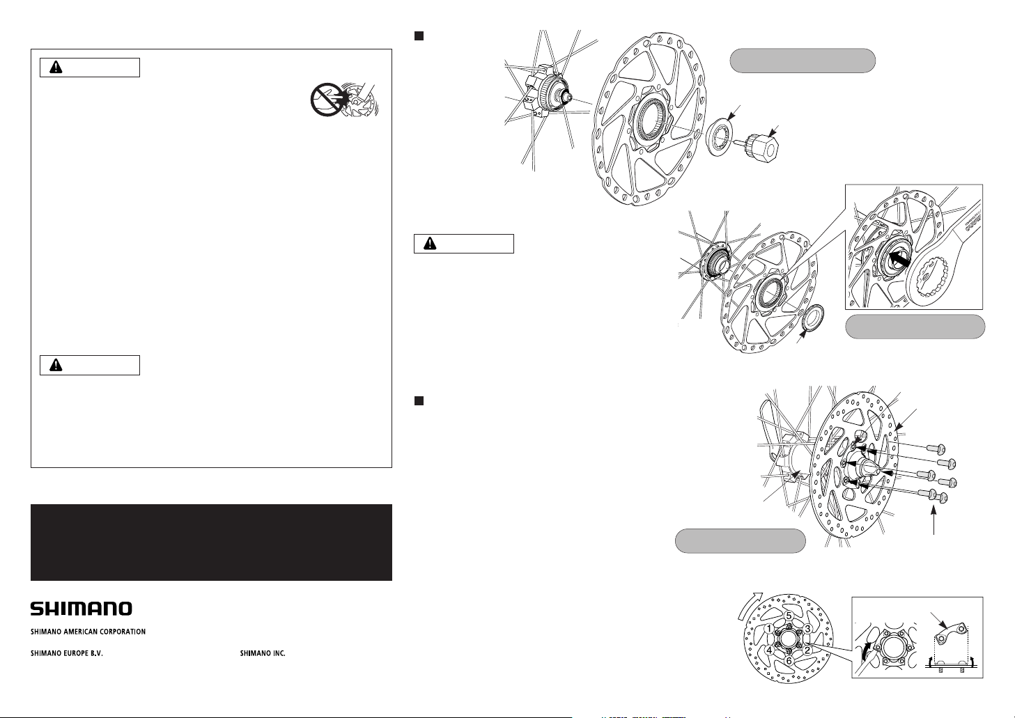
Rotor fixing lock ring
TL-FC36
When using the special tool (TL-FC36) to remove and
install the rotor mounting ring, be careful not to touch
the outside of the rotor with your hands. Wear gloves to
protect your hands from getting cut.
CAUTION
Tightening torque:
40 N·m {350 in. lbs.}
Rotor fixing
lock ring
TL-LR15
Center lock type
Tightening torque:
40 N·m {350 in. lbs.}
6 bolt type
Install the rotor and the rotor tightening plate to the hub,
and then install and tighten the bolts as shown in Fig. 1.
While wearing gloves, apply a force to the rotor to turn it
in a clockwise direction as shown in Fig. 2. While doing
this, tighten the rotor fixing bolts in the order shown in
the illustration.
Use a flat-tipped screwdriver or similar tool to bend the
edges of the tightening plate over the heads of the bolts
as shown in Fig. 3.
Fig. 1
Tightening plate
Rotor
Hub
Rotor fixing bolts
(#T25 torx) *
* TORX is a registered
trademark of Camcar LLC.
Fig. 2 Fig. 3
Tightening plate
Tightening torque:
2 - 4 N·m {18 - 35 in. lbs.}
Technical Service Instructions SI-0095A-001
Installation of
the rotor
SI-0095A-001-00
 Loading...