

Page 1
Series
RAPIDFIRE-Plus
Outer casing
Front derailleur
Front chainwheel
Bottom Bracket
Chain
Bottom bracket cable guide
Technical Service Instructions SI-6TE0A-003
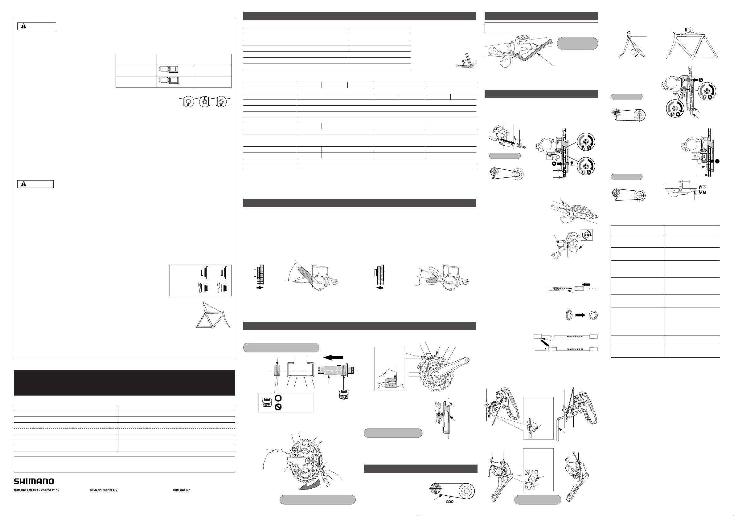
Front Drive System
Alivio
SL-M430
OT-SP40
FD-M430 / FD-M431
FC-M430 / FC-M430-8 / FC-M430-8-1A / FC-M431 / FC-M431-8
BB-UN26 (-E) / BB-UN26-K / BB-ES25 (-E) / BB-ES25-K
CN-HG53
SM-SP17 / SM-BT17
Specifications
Installation band diameters:
S (28.6 mm), M (31.8 mm), L (34.9 mm)
When using the S, M size, use an
installation band with a diameter of 28.6
mm, 31.8mm and install it to a L size
adapter.
Chainstay angle
FD-M430 / FD-M431
Applicable to both normal type and top route type X
Front chainwheel tooth difference 22T
12T
S, M, L
63° - 66°, 66° - 69°
50 mm
Min. difference between top and intermediate
Front derailleur installation band diameter
Chainstay angle (a)
Applicable chain line
Front Derailleur
Model number
X = Available
The level section of the chain guide
outer plate should be directly above
and parallel to the largest chainring.
Secure using a 5 mm Allen key.
Tightening torque :
5 - 7 N·m {44 - 60 in. lbs.}
Chainwheel
(largest chainring)
Chain guide
Installation of the lever
Chain length
Add 2 links (with the chain on both
the largest sprocket and the largest
chainring)
Largest sprocket Largest chainring
Chain
Use a handlebar grip with a maximum outer diameter of 36 mm.
Tightening torque :
5 N·m
{44 in. lbs.}
Cutting the outer casing
When cutting the outer casing, cut the opposite end to the end
with the marking. After cutting the outer
casing, make the end round so that the
inside of the hole has a uniform diameter.
After taking up the initial slack in the cable, re-secure to the front
derailleur as shown in the illustration.
Normal type Top route type
Pull
Pull
FD-M430
FD-M431
Chain
Chain guide outer
plate
Top adjustment
screw
A
B
Chain
Chain guide
inner plate
Outer casing adjustment barrel
Chain position
Smallest
sprocket
Largest
chainring
Chain position
Largest
sprocket
Intermediate
chainring
3. Top adjustment
Set so that the clearance
between the chain guide
outer plate and the chain is
0 - 0.5 mm.
4. Adjustment of the intermediate
chainring
When carrying out adjustment, set the
chain to the largest sprocket, and at the
front, set the chain to the intermediate
chainring. Adjust using the outer casing
adjustment barrel so that the clearance
between the chain guide inner plate and
the chain is 0 - 0.5 mm.
If the chain falls to the crank
side.
If shifting is difficult from the
intermediate chainring to the
smallest chainring.
Tighten the top adjustment screw
clockwise (about 1/4 turn).
Loosen the top adjustment screw
counterclockwise
(about 1/8 turn).
Loosen the low adjustment screw
counterclockwise
(about 1/4 turn).
If there is interference between
the chain and the front derailleur
inner plate at the largest
chainring.
If there is interference between
the chain and the front derailleur
outer plate at the largest
chainring.
Tighten the top adjustment screw
clockwise (about 1/8 turn).
Loosen the top adjustment screw
counterclockwise
(about 1/8 turn).
If the intermediate chainring is
skipped when shifting from the
largest chainring.
Loosen the outer casing
adjustment barrel
counterclockwise (1 or 2 turns).
If the chain falls to the bottom
bracket side.
If the lever is stiff when shifting
from the intermediate chainring
to the largest chainring
Tighten the outer casing
adjustment barrel clockwise
(1 or 2 turns).
Tighten the low adjustment screw
clockwise (about 1/2 turn).
Loosen the top adjustment screw
counterclockwise (about 1/4
turn).
5. Troubleshooting chart
After completion of steps 1 - 4, move the shifting lever to check the
shifting. (This also applies if shifting becomes difficult during use.)
If there is interference between
the chain and front derailleur
inner plate when the rear
sprocket is shifted to the largest
sprocket when the chainwheel is
at the intermediate chainring
position.
If shifting is difficult from the
intermediate chainring to the
largest chainring.
■ Refer to the Service Instructions for the Rear Drive
System for details on replacing and installing the
indicator unit.
SI-6TE0A-003-00
Adjust and then install the front derailleur as shown in the
illustration. Do not remove the Pro-Set alignment block at this time.
Gear teeth
should come
within this range
Pro-Set gauge
Pro-Set alignment block
Installation of the Front Derailleur, Bottom Bracket and Front Chainwheel
In order to realize the best performance, we recommend that the following combination be used.
To shift from a small chainring to a larger chainring
When lever (A) is pressed once, there is a shift of one step from a
small chainring to a larger chainring.
Example:
from intermediate chainring to largest chainring.
To shift from a large chainring to a smaller chainring
When lever (B) is pressed once, there is a shift of one step from a
large chainring to a smaller chainring.
Example:
from largest chainring to intermediate chainring.
Lever (B)
2-way release
Lever (A)
initial position
Gear shifting operation
This release lever is equipped with a 2-way release mechanism which allows release operations to be carried out by either pushing or pulling
the lever. Both lever (A) and lever (B) always return to the initial position when they are released after shifting. When operating one of the
levers, always be sure to turn the crank arm at the same time.
Use an 8 mm Allen key to install the front chainwheel.
Install using the special tool TL-UN74-S / TL-UN66. First install the
main body, then the adapter.
Main body
Adapter
Adapter / bottom bracket tightening torque:
50 - 70 N·m {435 - 608 in. lbs.}
Aluminum or steel
Plastic
Front chainwheel tightening torque:
35 - 50 N·m {305 - 435 in. lbs.}
8 mm Allen key
LL123
FC-M431 FC-M431-8
BB-UN26 (-E) BB-ES25 (-E) BB-UN26 (-K) BB-ES25 (-K)
9
44 - 32 - 22 T 44 - 32 - 22 T 48 - 36 - 26 T 44 - 32 - 22 T 48 - 36 - 26 T
FC-M430
BB-UN26 (-E)
FD-M430 / M431
FC-M430-8 FC-M430-8-1A
BB-ES25 (-E) BB-UN26 (-K) BB-ES25 (-K)
68 / 73 mm (1.37 X 24 T.P.I.)
LL113
50 mm
118 126
Model number
Spindle length
Chain line
Shell width (Thread dimensions)
Bottom Bracket
Model number
Rear sprockets
Front chainwheel tooth combination
Bolt circle diameter
Crank arm length
Pedal thread dimensions
Applicable chain
Applicable bottom bracket
Applicable front derailleur
170 / 175 mm
104 / 64 mm
B.C. 9/16" x 20T.P.I. (English thread)
CN-HG53
Front chainwheel
Inserting the inner cable
Insert the inner cable into the outer casing from the end with the
marking on it. Apply grease from the end with the marking in
order to maintain cable operating efficiency.
Marking
One Holland, Irvine, California 92618, U.S.A. Phone: +1-949-951-5003 Industrieweg 24, 8071 CT Nunspeet, The Netherlands Phone: +31-341-272222 3-77 Oimatsu-cho, Sakai-ku, Sakai-shi, Osaka 590-8577, Japan
* Service Instructions in further languages are available at : http://techdocs.shimano.com
Please note: specifications are subject to change for improvement without notice.(English) © Apr. 2011 by Shimano Inc. XBC IZM Printed in Singapore.
This service instruction explains how to use and maintain the Shimano bicycle parts which have been used on your new bicycle.
For any questions regarding your bicycle or other matters which are not related to Shimano parts, please contact the place of
purchase or the bicycle manufacturer.
Attach the same outer end cap to the cut end of the outer casing.
Outer end cap
SIS Adjustment
Be sure to follow the sequence described below.
1. Low adjustment
First remove the Pro-Set alignment block .
Next, set so that the clearance between the chain guide inner
plate and the chain is 0 - 0.5 mm.
FD-M431
FD-M430
Low adjustment
screw
Chain
Pro-Set alignment
block
Chain guide
inner plate
Chain position
Largest
sprocket
Smallest
chainring
5 mm Allen key
2. Connecting and securing
the inner cable
Operate lever (B) 2 or more
times, check on the indicator that
the low position is correct, and
then secure the inner cable.
Lever (B)
Cut off the excess length of inner cable and then install the inner
end cap.
While firmly pulling the inner cable, secure by tightening the fixing
bolt with a 5 mm Allen key.
< Normal type >
• FD-M430
< Top route type >
Tightening torque :
5 - 7 N·m {44 - 60 in. lbs.}
< Normal type >
• FD-M431
< Top route type >
5 mm Allen key
Note:
Pass the cable
through as shown
in the illustration.
Wire
fixing bolt
Note:
Pass the cable
through as shown
in the illustration.
Wire
fixing bolt
Install the inner hole cover by
turning it as shown in the
illustration until it stops.
Do not turn it any further than this,
otherwise it may damage the screw
thread.
Unit cover
Inner hole cover
Feed lever
• Install the shifting lever in a position where it will not obstruct brake
operation and gear shifting operation.
• Do not use in a combination which causes brake operation to be
obstructed.
General Safety Information
WARNING
“Maintenance interval depends on the usage and riding circumstances. Clean regularly the chain
with an appropriate chaincleaner. Never use alkali based or acid based solvents such as rust
cleaners. If those solvent be used chain might break and cause serious injury.”
• Use the reinforced connecting pin only for connecting the narrow type of chain.
• There are two different types of reinforced connecting pins available. Be sure to check the table below before selecting which
pin to use.
If connecting pins other than reinforced connecting pins
are used, or if a reinforced connecting pin or tool which
is not suitable for the type of chain is used, sufficient
connection force may not be obtained, which could
cause the chain to break or fall off.
• If it is necessary to adjust the length of the chain due
to a change in the number of sprocket teeth, make the
cut at some other place than the place where the chain
has been joined using a reinforced connecting pin or an end pin. The chain will be damaged if it
is cut at a place where it has been joined with a reinforced connecting pin or an end pin.
• Be careful not to let the cuffs of your clothes get caught in the chain while riding, otherwise you
may fall off the bicycle.
• Check that the tension of the chain is correct and that the chain is not damaged. If the tension
is too weak or the chain is damaged, the chain should be replaced. If this is not done, the chain
may break and cause serious injury.
• Use a front chainwheel which is compatible with 9-speed chains in conjunction with Shimano CN-HG73 and CN-HG53 chains. If
a chainwheel for an 8-speed chain or less is used, front chainwheel gear shifting problems may occur, or the chain pins might
fall out, causing the chain to break.
• It is important to periodically check the tightening torques for the crank arms and pedals. After riding approximately 100 km (60
miles), re-check the tightening torques. If the tightening torques are too weak, the crank arms or pedals may come off and the
bicycle may fall over, and serious injury may occur as a result.
• Check that there are no cracks in the crank arms before riding the bicycle. If there are any cracks, the crank arm may break and
you may fall off the bicycle.
• Obtain and read the service instructions carefully prior to installing the parts. Loose, worn or damaged parts may cause the
bicycle to fall over and serious injury may occur as a result. We strongly recommend only using genuine Shimano replacement
parts.
• Obtain and read the service instructions carefully prior to installing the parts. If adjustments are not carried out correctly, the
chain may come off and this may cause you to fall off the bicycle which could result in serious injury.
• Read these Technical Service Instructions carefully, and keep them in a safe place for later reference.
• If the chain is on the smallest or intermediate chainring, there is the danger of injury from the tips of the teeth on the largest
chainring.
Note
• In addition, if pedaling performance does not feel normal, check this once more.
• Before riding the bicycle, check that there is no play or looseness in the connection. Also, be sure to retighten the crank arms
and pedals at periodic intervals.
• When installing the pedals, apply a small amount of grease to the threads to prevent the pedals from sticking. Use a torque
wrench to securely tighten the pedals. Tightening torque: 35 - 55 N·m {305 - 479 in. lbs.}.The right-hand crank arm has a righthand thread, and the left-hand crank arm has a left-hand thread.
• Do not wash the bottom bracket with high-pressure jets of water.
• If you feel any looseness in the bottom bracket axle, the bottom bracket should be replaced.
• If gear shifting operations do not feel smooth, wash the derailleur and lubricate all moving parts.
• If the amount of looseness in the links is so great that adjustment is not possible, you should replace the derailleur.
• You should periodically wash the chainrings in a neutral detergent and then lubricate them again. In addition, cleaning the chain
with neutral detergent and lubricating it can be a effective way of extending the useful life of the chainrings and the chain.
• The cuffs of your clothing may get dirty from the chain while riding.
• If the chain keeps coming off the chainrings during use, replace the chainrings and the chain.
• When the chain is in the position shown in the illustration, the chain may contact the front
chainrings or front derailleur and generate noise. If the noise is a problem, shift the chain
onto the next-larger rear sprocket or the one after.
• Apply grease to the bottom bracket before installing it.
• For smooth operation, use the specified outer casing and the bottom bracket cable guide.
• This front derailleur is for triple front chainwheel use only. It cannot be used with the
double front chainwheel, as the shifting points do not match.
• When installing the top route type, choose a frame that has three outer casing holders as
shown in the illustration at right.
• Use an outer casing which still has some length to spare even when the handlebars are turned all the way
to both sides. Furthermore, check that the shifting lever does not touch the bicycle frame when the
handlebars are turned all the way.
• Grease the inner cable and the inside of the outer casing before use to ensure that they slide properly.
• Operation of the levers related to gear shifting should be made only when the front chainwheel is turning.
• Do not disassemble the indicator and shifting lever unit, as this may damage them or cause mis-operation.
• Parts are not guaranteed against natural wear or deterioration resulting from normal use.
• For maximum performance we highly recommend Shimano lubricants and maintenance products
• For any questions regarding methods of installation, adjustment, maintenance or operation, please contact a professional
bicycle dealer.
Chain toolChain
9-speed super narrow
chain such as
CN-7701 / CN-HG93
8- / 7- /6-speed narrow
chain such as
CN-HG50 / CN-HG40
Reinforced
connecting pin
TL-CN32 /TL-CN27
TL-CN32 /TL-CN27
6.5mm
7.1mm
Silver
Black
Reinforced Connecting Pin
End Pin Link Pin
Outer casing holders
CAUTION
Front
chainrings
Rear
sprockets
 Loading...