

One Holland, Irvine, California 92618, U.S.A. Phone: +1-949-951-5003
High Tech Campus 92, 5656 AG Eindhoven, The Netherlands Phone: +31-402-612222 3-77 Oimatsu-cho, Sakai-ku, Sakai-shi, Osaka 590-8577, Japan
Please note: specifi cations are subject to change for improvement without notice. (English)
© Jun. 2017 by Shimano Inc. ITP
UM-7GC0B-005-00
User's manual
System information Display
User's manuals in other languages are available at :
http://si.shimano.com
IMPORTANT NOTICE
• Contact the place of purchase or a bicycle dealer for information on installation and adjustment
of the products which are not found in the user's manual. A dealer's manual for professional
and experienced bicycle mechanics is available on our website (http://si.shimano.com).
• Do not disassemble or alter this product.
• The Bluetooth
®
word mark and logos are registered trademarks owned by the Bluetooth SIG,
Inc. and any use of such marks by SHIMANO INC. is under license.
Other trademarks and trade names are those of their respective owners.
For safety, be sure to read this user's manual thoroughly
before use, and follow them for correct use.
Important Safety Information
For replacement information, contact the place of purchase or a bicycle dealer.
WARNING
• When the shifting switch is operated, the motor which drives the front derailleur will operate
to the shifting position without stopping, so be careful not to get your fi ngers caught.
• After reading the user's manual carefully, keep it in a safe place for later reference.
Note
• When using a system information display, combine it with one of the following units.
External type: BM-DN100, Built-in type: BT-DN110
• Be sure to attach dummy plugs to any unused terminals. If water gets into any of the
components, operating problems or rusting may result.
• This is a small waterproof connector. Do not repeat connecting and disconnecting it. It may
impair the function.
• Be careful not to let water get into the terminal.
• The components are designed to be fully waterproofed to withstand wet weather riding
conditions; however, do not deliberately place them into water.
• Do not clean the bicycle in a high-pressure car wash. If water gets into any of the components,
operating problems or rusting may result.
• Handle the products carefully, and avoid subjecting them to any strong shocks.
• Do not use thinners or similar substances to clean the products. Such substances may damage
the surfaces.
• Contact the place of purchase for updates of the product software. The most up-to-date
information is available on the Shimano website.
• Disconnect Bluetooth LE when not using E-TUBE PROJECT for smartphones/tablets.
Using the system information display without disconnecting Bluetooth LE may result in high
battery power consumption.
• Products are not guaranteed against natural wear and deterioration from normal use and
aging.
• For maximum performance we highly recommend Shimano lubricants and maintenance
products.
Regular inspections before riding the bicycle
Before riding the bicycle, check the following items. If any problems are found with the
following items, contact the place of purchase or a bicycle dealer.
• Is the system information display securely installed to the handlebar?
• Is there suffi cient charge remaining in the battery?
• Is there any noticeable damage to the electric wires?
• Is the dummy plug attached to the terminal?
Names of parts
Some items may not be displayable or selectable depending on the connected components and
software version. Consult a dealer regarding the usable items for the product you are using.
Mode
switch
Terminal
Charging
port
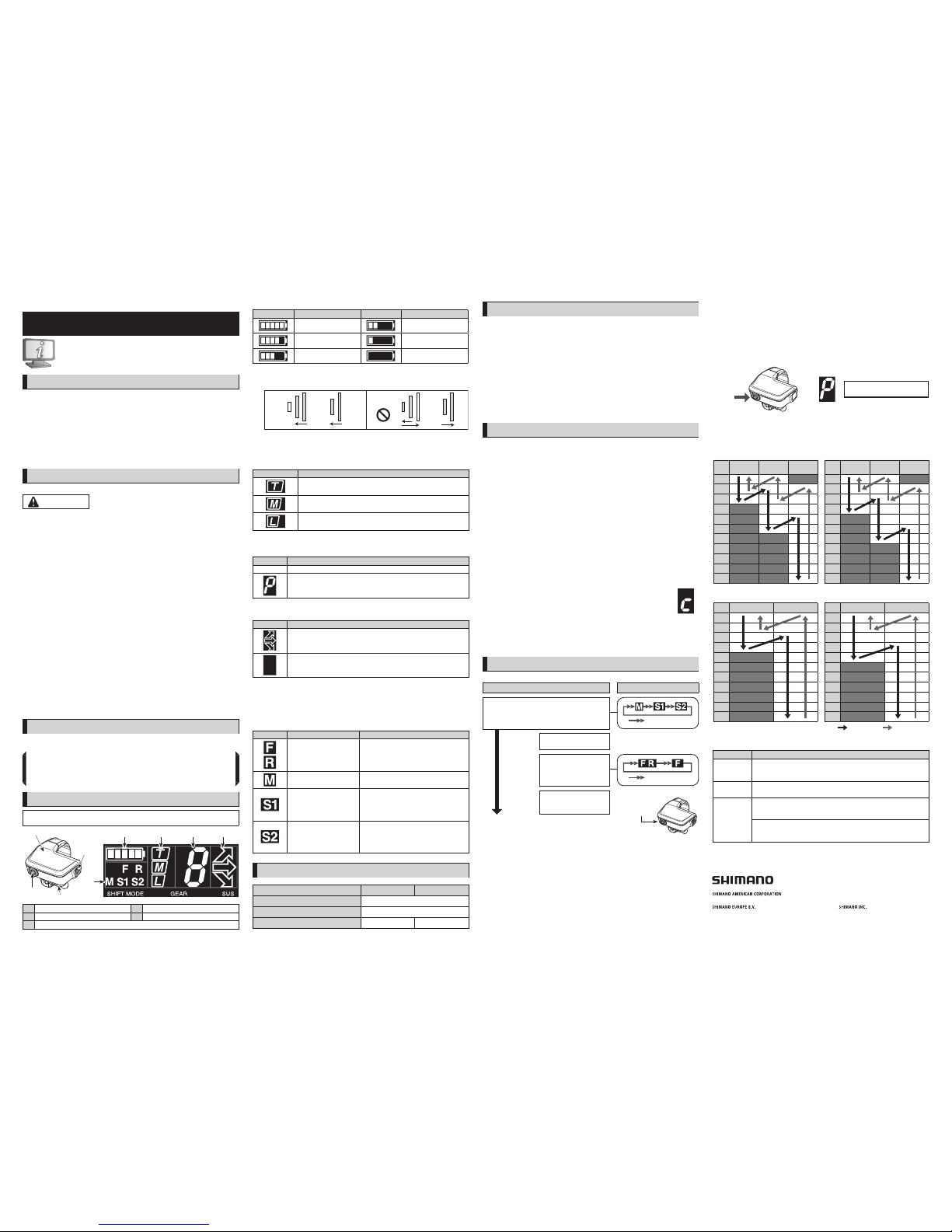
Display
A B C D
E
A Battery level D Suspension setting
B Front derailleur Gear position E Operation mode
C
Rear derailleur Gear position/RD Protection Reset mode
A. Battery level
Display Battery level Display Battery level
81% - 100% 26% - 40%
61% - 80% 1% - 25%
*1*2*3
41% - 60% 0%
*3
* 1 When the battery level becomes low, the operation of the suspensions is restricted to the
unlocking direction. The operation of the rear suspension is restricted fi rst, then the front
suspension's is also restricted.
* 2 When the battery level drops below 5%, the operation of the front derailleur is restricted.
* 3 When the battery level decreases further, both the suspensions and derailleurs cease
operating, with the derailleurs fi xed at the last shifted position. The battery indicator blinks
for 2 seconds at the time of input operation. We recommend early charging of the battery.
B. Front derailleur Gear position
The gear position of the front derailleur is displayed.
Display Gear position
Largest chainring
Middle chainring
Smallest chainring
* In the case of double specifi cation, only the largest chainring and smallest chainring are
displayed.
C. Rear derailleur Gear position/RD Protection Reset mode
Display Details
Number The gear position of the rear derailleur is displayed.
RD Protection Reset will operate.
D. Suspension setting
Three types of front and rear suspension combinations can be confi gured.
Display Details
If the suspension settings are already confi gured, one of the settings can be
selected from the screen indications.
*1*2
If the suspension settings are not confi gured, the suspensions are not
connected, or the battery level is running low, the display will be blank.
* 1 Suspension settings are confi gured in E-TUBE PROJECT. For details, consult a dealer or an
agency.
* 2
Depending on the type of suspension, settings may be factory confi gured at the time of
shipment. Check the indications displayed on the system information display screen, and if the
arrows are displayed, be sure to check the setting details.
E. Operation mode
The operation mode is displayed.
Display Mode Details
Front derailleur/
Rear derailleur adjustment
Adjustment setting is done in this mode. For
the setting procedure, contact a dealer or an
agency.
Manual shift Gears are shifted manually in this mode.
Shift mode 1
The shift mode set in E-TUBE PROJECT can
be used. The initial setting for MTB is
Synchronized shift 1.
This setting mode is designed for riders with
strong legs.
Shift mode 2
The shift mode set in E-TUBE PROJECT can
be used. The initial setting for MTB is
Synchronized shift 2.
This setting mode is designed for courses
with considerable terrain variation.
Specifi cations
SC-MT800 SC-M9051
Frequency band 2,402 – 2,480 MHz
Maximum radio-frequency power +4 dBm
Firmware version 4.0.9 – 4.1.1 –
Functions
ANT connection
The system information display transmits the following three types of information to compatible
cycle computers or receivers.
1) Number of gears (front, rear)
2) DI2 battery level
3) Adjustment mode information
For information on which of the above types of information is to be displayed, refer to the
manual for your cycle computer or receiver.
* The latest functions can be checked by updating the software via E-TUBE PROJECT. For details,
consult the place of purchase.
Bluetooth
®
LE connection
E-TUBE PROJECT for smartphones/tablets may be used if a Bluetooth LE connection is established
with a smartphone/tablet.
How to make connections
ANT connection
To make a connection, the cycle computer needs to be in connection mode. For information on
how to put the cycle computer into connection mode, refer to the manual for the cycle
computer.
1) Put the cycle computer into connection mode.
2) ■When using an external battery
Check that the electric wires are connected to the system information display. Then, remove
and remount the external battery.
■When using a built-in battery
Check that the electric wires are connected to the system information display. Then, remove
the electric wires from the system information display and reconnect them.
(Connection transmission begins about 30 seconds after the battery is remounted or the
electric wires are reconnected to the system information display.)
3) This completes the connection process.
Check on the cycle computer to see if connection was successful.
If a connection cannot be made in the way described above, refer to the manual for your cycle
computer.
For information on how to show the number of gears or the DI2 battery level, refer to the
manual for the cycle computer.
Bluetooth
®
LE connection
Before setting up a connection, turn on Bluetooth LE on the smartphone/tablet.
1) Open E-TUBE PROJECT and set it to listen for Bluetooth LE signals.
2) Press the mode switch until "C" appears on the display. The cycle computer will
begin signal transmission. The unit name displays in E-TUBE PROJECT.
* Release the mode switch or button as soon as the unit on the bicycle begins
signal transmission.
If the mode switch or button is held down for any longer, a different mode will
be activated.
3) Select the unit name displayed on screen.
* To disconnect, cancel the Bluetooth LE connection from the smartphone/tablet. (The cycle
computer will exit connection mode and return to regular operation mode.)
How to operate
Switching operating modes
Operation mode Sub-operation mode
Shift mode
Double click
Press and hold
0.5 seconds
or more
Bluetooth LE
connection mode
2 seconds
or more
Adjustment mode
Double click
5 seconds
or more
RD Protection Reset mode
Mode switch
To end Adjustment mode or RD Protection Reset mode, press for 0.5 seconds or more.
For the setting procedure, contact a dealer or an agency.
About the RD Protection function
Rotate the front chainwheel while restoring operation after the RD Protection function has
activated.
In order to protect the system from falls etc., the RD Protection function will operate when the
rear derailleur is subjected to a strong impact. The connection between the motor and the link is
momentarily severed so that the rear derailleur will no longer operate. If this happens, press the
mode switch for 5 seconds or more. This will restore the connection between the motor and the
link, and clear the RD Protection function for the rear derailleur. If recovery cannot be
performed through switch operation, manual operation is also possible. Consult with a
distributor in advance.
5 seconds or
more
RD Protection Reset
Synchronized shift setting (only compatible with XTR DI2 and XT DI2)
Front gear position changes according to rear gear position. The initial settings for MTB are as
shown in the tables. These settings can be changed in E-TUBE PROJECT. For details, consult a
dealer or an agency.
<Triple specifi cation>
Shift mode 1
CS
Smallest
chainring
Middle
chainring
Largest
chainring
1
2
3
4
5
6
7
8
9
10
11
Shift mode 2
CS
Smallest
chainring
Middle
chainring
Largest
chainring
1
2
3
4
5
6
7
8
9
10
11
<Double specifi cation>
Shift mode 1
CS
Smallest chainring Largest chainring
1
2
3
4
5
6
7
8
9
10
11
Shift mode 2
CS
Smallest chainring Largest chainring
1
2
3
4
5
6
7
8
9
10
11
Upshifting Downshifting
About the beep
Beeps are set to sound in the following situations during gear operation.
Beep sounds Situation
One short
beep
Indicates that the gear shifting limit has been reached. (When the chain is
on the highest gear for both front and rear or lowest gear for both front
and rear)
Two short
beeps
Indicates that the front gears are being shifted in shift mode. These beeps
sound the next time the front gears are shifted.
One long
beep
Indicates that the front derailleur cannot be shifted when the battery is
running low. Blinking continues for 2 seconds after the sound has stopped.
(Only one beep sounds when the gears are shifted)
Indicates that there is an error with the suspension.
All suspension mode arrows blink and continue to blink for 2 seconds after
the sound has stopped.
 Loading...