

Shimano NEXUS BL-IM65 - TECHNICAL, NEXUS CJ-8S20 - TECHNICAL, NEXUS SL-8S20 - TECHNICAL, Nexus SL-8S20, Nexus BL-IM65 Service Instructions Manual
...Page 1
CJ-8S20
JAPAN
LOCK
2 mm Allen key
or #14 spoke
Pulley hole
Turn the
pulley
Pull out from
the outer
casing holder
CJ-8S20
JAPAN
LOCK
3
1
Remove the inner
cable fixing bolt unit
2
CJ-8S20
JAPAN
LOCK
CJ-8S20
JAPAN
LOCK
C R
V
V
C R
C R
V
V
C R
CJ-8S20
JAPAN
LOCK
CJ-8S20
JAPAN
LOCK
CJ-8S20
JAPAN
LOCK
CJ-8S20
JAPAN
CJ-8S20
JAPAN
LOCK
CJ-8S20
JAPAN
LOCK
SI-6FD0A
SL-8S20
BL-IM65
CJ-8S20
2
1
1
2
3
CJ-8S20
JAPAN
LOCK
CJ-8S20
JAPAN
LOCK
CJ-8S20
JAPAN
LOCK
CJ-8S20
JAPAN
LOCK
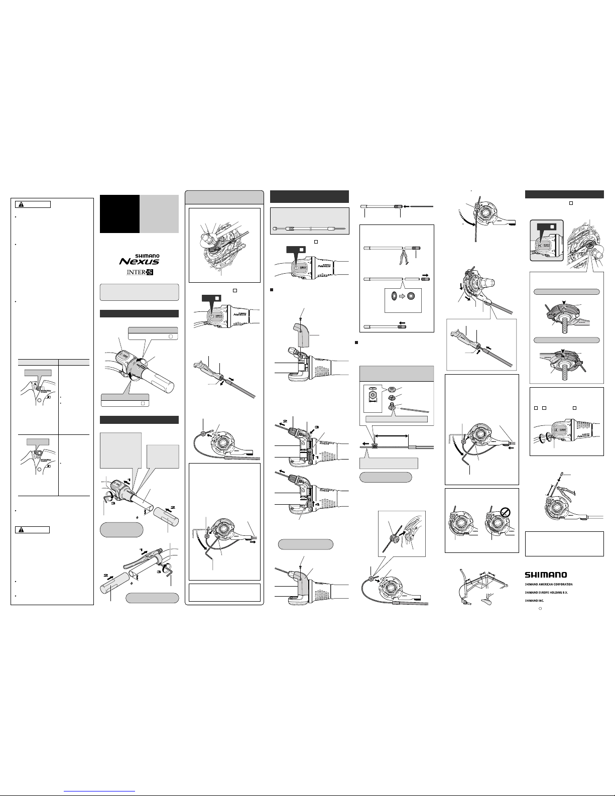
Revo-shift Lever
Cassette Joint
Brake Lever
Be sure to shift the lever one gear at a time, and
reduce the force being applied to the pedals
during shifting. If you try to force operation of the
shifting lever while the pedals are being turned
strongly, your feet may come off the pedals and
the bicycle may topple over, which could result
in serious injury.
Pedaling becomes heavier
Indicator moves toward
8
Indicator moves toward
1
Pedaling becomes lighter
Indicator
Revo-shift lever
General Safety Information
CAUTION
WARNING
– To avoid serious injuries:
– To avoid serious injuries:
NOTE:
For maximum performance we highly
recommend Shimano lubricants and
maintenance products.
Parts are not guaranteed against natural wear
or deterioration resulting from normal use.
Obtain and read the service instructions
carefully prior to installing the parts. Loose,
worn, or damaged parts may cause serious
injury to the rider.
We strongly recommend only using genuine
Shimano replacement parts.
It is important to completely understand the
operation of your bicycle's brake system.
Improper use of your bicycle's brake system
may result in a loss of control or an accident,
which could lead to severe injury. Because
each bicycle may handle differently, be sure to
learn the proper braking technique (including
brake lever pressure and bicycle control
characteristics) and operation of your bicycle.
This can be done by consulting your
professional bicycle dealer and the bicycle's
owners manual, and by practicing your riding
and braking technique.
These brake levers are equipped with a mode
switching mechanism to make them
compatible with cantilever brakes and Roller
Brakes or V-Brakes with power modulator.
Use the brake levers with mode switching
mechanism in the combinations given above.
Read these Technical Service Instructions
carefully, and keep them in a safe place for
later reference.
Technical Service Instructions
Be sure to read these service instructions in
conjunction with the service instructions for
the Inter-8 hub before use.
Revo-shift lever operation
Turn the Revo-shift lever to shift to each of the eight
gears.
Mode position
Applicable brake
The V indicates the mode
position for compatibility
with V-Brakes with power
modulator.
V position
C/ R position
The C indicates the mode
position for compatibility
with cantilever brakes.
The R indicates the mode
position for compatibility
with Roller Brakes.
If the incorrect mode is selected it
may cause either excessive or
insufficient braking force to occur,
which could result in dangerous
accidents.
Be sure to select the mode in
accordance with the instructions
given in the table below.
Tighten
Tighten
Handlebar
Half grip
3 mm Allen key
Clamp bolt
Tightening torque:
6 – 8 N·m {60 – 80 kgf·cm}
Installation of the lever
Install the lever as shown in the illustration.
5 mm Allen key
Clamp bolt
Grip
Tightening torque:
0.1 – 0.2 N·m {1 – 2 kgf·cm}
V-Brakes with power
modulator
Cantilever brakes
Roller Brakes
Note:
If reusing the cable, refer to steps 7 to 9 in
"Installation of the shifting cable".
Disconnect the cable from the cassette joint
when removing the rear wheel from the
frame.
1
Set the Revo-shift lever to .
Pull the outer casing out from the outer
casing holder of the cassette joint, and then
remove the inner cable from the slit in the
bracket.
Remove the inner cable fixing bolt unit from
the cassette joint pulley.
Disconnecting the shifting cable when
removing the rear wheel from the frame
Cassette joint
Inner cable fixing bolt unit
Cassette joint pulley
Remove from
the slit
Pull out from outer
casing holder
Bracket
Slit
Set to
1
If it is difficult to pull the outer casing out
from the outer casing holder of the cassette
joint, insert a 2 mm Allen key or a #14
spoke into the hole in the cassette joint
pulley, and then turn the pulley to loosen
the inner cable. Then remove the inner
cable fixing bolt unit from the pulley first,
and after this remove the outer casing from
the outer casing holder.
Outer casing holder
CJ-8S20
JAPAN
2
1
Installation of the shifting
cable
Use a shifting cable with one inner cable drum.
Cable with one inner cable drum /
SIS-SP40 (4 mm dia.)
Set to
1
Cover fixing screw
Upper cover
Hole in cable adjustment bolt
Groove in cable guide
Hole in winder unit
Recess in winder unit
Loosen the cover fixing screw, and then remove
the upper cover.
Pass the inner cable from the hole in the winder
unit through the hole in the cable adjustment bolt.
Next, insert the inner cable into the groove of the
cable guide, and pull the inner cable so that the
inner cable drum fits into the recess in the winder
unit.
Revo-shift lever side
Cover fixing screw
Upper cover
Replace the upper cover and tighten the cover
fixing screw.
101 mm
Gap in pulley
Bring the cable around to the cassette joint pulley,
hold so that the inner cable fixing nut is facing to
the outside (toward the fork end), and then slide
the flats part of the inner cable fixing washer into
the gap in the pulley.
Flats part of inner
cable fixing washer
Inner cable
fixing nut
Pulley
After checking that the end of the outer casing is
sitting securely in the cable adjustment bolt of the
Revo-shift lever, attach the inner cable fixing bolt
unit to the inner cable.
Cassette joint side
Inner cable fixing bolt unit
10 mm
Note: Do not use this inner cable fixing bolt
unit with the CJ-4S30 cassette joint.
Inner cable fixing nut
Inner cable fixing
washer
(Black)
Inner cable fixing bolt
Pass the inner cable through the hole.
Pull the inner cable while attaching
the inner cable fixing bolt unit.
Tightening torque:
4 – 6 N·m {40 – 60 kgf·cm}
Pulley
Bracket
Guide
OK Not OK
Secure the cable to the frame with the outer
casing bands.
10 cm
10 cm
15 cm
Turn the
cable 60
Hook
Turn the cable 60 counterclockwise and attach it
to the hook.
Attach the inner cable to the pulley as shown in
the illustration, pass the inner cable through the
slit in the cassette joint bracket, and then insert
the end of the outer casing securely into the outer
casing holder.
Inner cable
Slit
Outer casing holder
Pass through
the slit.
Note:
Check that the inner cable is correctly seated
inside the pulley guide.
If first inserting the outer casing into the
outer casing holder is easier, then first insert
the outer casing into the outer casing holder,
and then insert a 2 mm Allen key or a #14
spoke into the hole in the cassette joint
pulley, and then turn the pulley so that the
inner cable fixing bolt unit fits into the gap in
the pulley.
Hole in pulley
Insert into the
outer casing
holder
Insert the inner cable
fixing bolt unit
Guide
Outer casing bands
Bracket
Insert into the
outer casing
holder.
2 mm Allen key
or #14 spoke
Turn the
pulley
Adjusting the cassette joint
Set the Revo-shift lever to .
Check to be sure that the yellow setting lines on
the cassette joint bracket and pulley are aligned at
this time.
After adjusting the cassette joint, cut off the
excess length of inner cable and then install the
inner end cap.
4
Inner end cap
Cable adjustment bolt
Cassette joint
pulley
Cassette joint
pulley
Yellow setting lines
15 – 20 mm
Should be straight
Should be straight
When bicycle is upside down
When bicycle is standing up
If the yellow setting lines are not aligned,
turn the cable adjustment bolt of the Revoshift lever to align the setting lines. After this,
move the Revo-shift lever once more from
to and then back to , and then recheck to be sure that the yellow setting lines
are aligned.
The yellow setting lines on the cassette joint
are located in two places. Use the one that
is easiest to see.
Cassette joint bracket
Cassette joint bracket
Pass the inner cable through the SIS-SP40 outer
casing through the end with the plastic cap.
If cutting the outer casing, cut it near the end
with the plastic cap while the cap is still
attached. Then make the cut end perfectly
round and attach the plastic cap.
(Lever side)
Remove the plastic cap.
Make the cut end
perfectly round.
Attach the plastic cap.
Aluminum cap
Plastic cap
Plastic cap
1
Set the Revo-shift lever to .
4 41
Apr. 2004 by Shimano Inc. PIT. SZK. Printed in Singapore
C
22.2 mm
22.2 mm
In case of using
Shimano half grip, the
straight section of the
handlebar should be
166 mm or more in
length; attach the
Revo-shift lever to this
straight section.
Leave a gap of
0.5 mm between
the Revo-shift
lever and the
half grip.
Tightening torque:
2 – 2.5 N·m
{20 – 25 kgf·cm}
Set to
4
®
One Holland, Irvine, California 92618, U.S.A. Phone: +1-949-951-5003
Industrieweg 24, 8071 CT Nunspeet, The Netherlands Phone: +31-341-272222
3-77 Oimatsu-cho, Sakai, Osaka 590-8577, Japan
1.
2.
1.
5.
8.
1.
2.
9.
10.
6.
7.
2.
3.
4.
3.
These service instructions explain how to use and
maintain the Shimano bicycle parts which have been
used on your new bicycle. For any questions regarding
your bicycle or other matters which are not related to
Shimano parts‚ please contact the place of purchase or
the bicycle manufacturer.
 Loading...