

Page 1
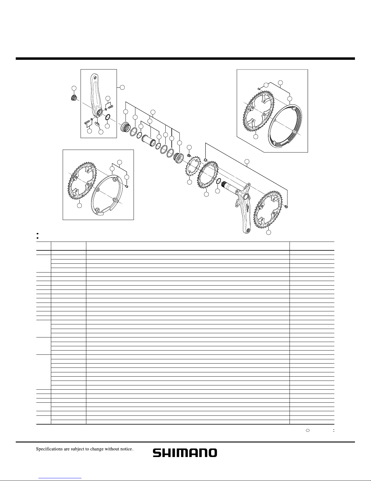
FC-M582
FC-M591
FC-M770
A: Same parts.
B: Parts are usable, but differ in materirals, appearance, finish, size, etc.
Absence of mark indicates non-interchangeability.
INTERCHANGE-
ABILITY
DESCRIPTION
SHIMANO
CODE NO.
ITEM
NO.
1
2
3
4
5
6
7
8
9
10
11
12
13
14
15
16
17
18
19
20
21
22
*
Y-1F8
Y-1LD
Y-1LD
Y-1LD
Y-1LD
Y-1KS
Y-1FU
Y-1F3
Y-1LD
Y-1LD
Y-1F8
Y-1J8
Y-1TF
Y-1LD
Y-1FM
Y-1FM
Y-1J8
Y-1LD
Y-1FV
Y-1LD
Y-1J8
Y-1LD
Y-1J8
Y-1LD
Y-1GX
Y-1GX
Y-1LD
Y-1LD
Y-1GX
Y-1LD
Y-1LD
Y-1LD
Y-1J8
Y-1CY
Y-1GX
Y-1LD
Y-1LD
Y-1D2
Y-1LD
Y-1LD
11100
98010
98020
98030
98040
98030
98120
16000
98050
98060
13000
98060
21000
98070
98020
98030
22000
22000
26000
26000
98070
98080
98080
98090
98050
98060
98100
98110
98090
98160
98120
98130
98090
98020
14000
98140
98150
98010
12000
13000
Crank Arm Fixing Bolt
Left Hand Crank Arm 170 mm (Silver) for FC-M590-S
Left Hand Crank Arm 170 mm (Black) for FC-M590-L
Left Hand Crank Arm 175 mm (Silver) for FC-M590-S
Left Hand Crank Arm 175 mm (Black) for FC-M590-L
Clamp Bolt (M6 x 19) & Washer
Plate
Ring
Adapter Unit
Left Hand Adapter (B.C.1.37" x 24T) English Thread
Spacer (2.5 mm)
Inner Cover & O-Ring
O-Ring
Right Hand Adapter (B.C.1.37" x 24T) English Thread
Double Gear Fixing Bolt (M8 x 8.5) & Nut (4 sets)
Inner Gear Fixing Bolt (M8 x 8.5 / 4 pcs.)
Chainring 22T (Silver) for FC-M590-S
Chainring 22T (Black) for FC-M590-L
Chainring 26T (Silver) for FC-M590-S
Chainring 26T (Black) for FC-M590-L
Chainring 32T (Silver) for FC-M590-S
Chainring 32T (Black) for FC-M590-L
Chainring 36T (Silver) for FC-M590-S
Chainring 36T (Black) for FC-M590-L
Chainring 44T (Black) for FC-M590-S
Chainring 44T (Black) for FC-M590-S Chain Guard
Chainring 44T (Gray) for FC-M590-L
Chainring 44T (Gray) for FC-M590-L Chain Guard
Chainring 48T (Black) for FC-M590-S
Chainring 48T (Black) for FC-M590-S Chain Guard
Chainring 48T (Gray) for FC-M590-L
Chainring 48T (Gray) for FC-M590-L Chain Guard
44T Chain Guard & Fixing Bolts
44T Chain Guard Fixing Bolt (4 pcs.)
44T Chain Guard
48T Chain Guard & Fixing Screws for FC-M590-S
48T Chain Guard & Fixing Screws for FC-M590-L
48T Chain Guard Fixing Screw (4 pcs.)
48T Chain Guard for FC-M590-S
48T Chain Guard for FC-M590-L
Chainring teeth combinations: 44 -- 32 -- 22T / 48 -- 36 -- 26T
Bolt circle diameter: 104 mm... (For outer gear and middle gear), 64 mm...(For inner gear)
AAA
AA
AAA
AAA
AA
AAA
AA
AAA
AA
AA
AA
AA
AA
AA
AA
AA
AA
AA
AA
AA
AA
AA
AA
AA
AAA
AA
AA
AA
AA
AA
AA
Dec.-2009-2926B
Shimano Inc. I
C
44T Chain Guard Type
48T Chain Guard Type
1
2
3
3
4
5
5
6
7
8
8
8
9
10
10
11
12
13
14
15
16
16
16
20
21
22
17
18
19
DEORE Front Chainwheel
Silver Version
Black Version
FC-M590-S
FC-M590-L
Page 2
SM-BB51
FC-M590 / FC-M591
SM-BB50
FC-M543-K / FC-M542 / FC-M533-K / FC-M532
68, 73 mm (1.37 X 24 T.P.I.)
FC-M532 / FC-M533-K
44-32-22T / 48-36-26T
68, 73 mm (1.37 X 24 T.P.I.)
SM-BB50
FC-M590 / FC-M591
44-32-22T / 48-36-26T
104 mm / 64 mm
170 mm, 175 mm
50 mm
SM-BB51
FC-M542
44-32-22T
FC-M543-K
44-32-22T / 48-36-26T
Band Type Bracket Type
< Normal type > < Chain case specifications >
Band Type Chaincase Stay Type Bracket Type
Technical Service Instructions SI-0093A-002
Front Chainwheel (2-piece crank)
Specifications
Chainwheel
Model number
Chainwheel tooth combination
Bolt circle diameter
Crank arm length
Chain line
Bottom bracket shell width (Thread dimensions)
Applicable bottom bracket
68 mm
BB mounttype bracket
73 mm 73 mm
68 mm
Chaincase stay
73 mm 73 mm
68 mm
BB mounttype bracket
73 mm
F
A
F
A
F
A
FAF
C
F
C
F
A
F
A
F
A
F
A
F
A
F
A
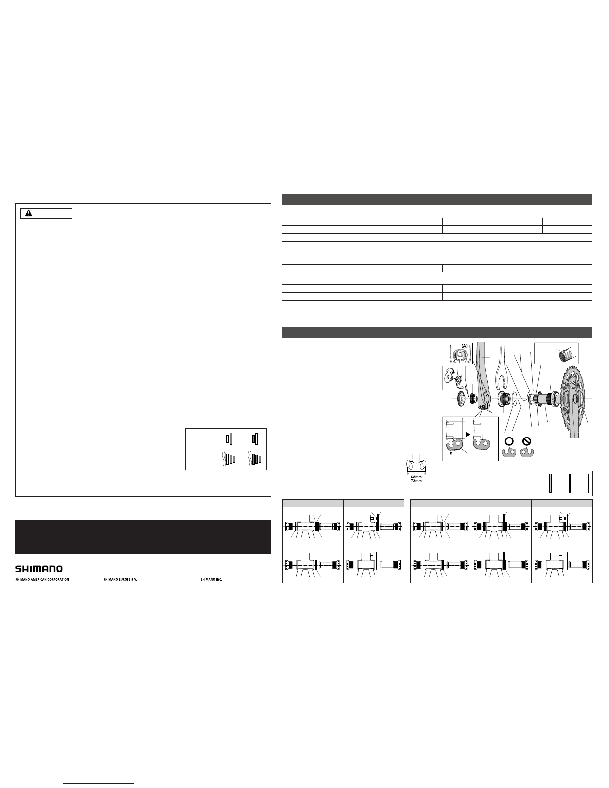
Installation of the Front Chainwheel
Follow the procedure in the figure.
1, 2 Use the special tool TL-FC32/36 to install the right adapter
(counterclockwise thread) and the left adapter (clockwise thread).
Tightening torque: 35 - 50 N·m {305 - 435 in. lbs.}
3 Insert the right crank unit.
4 Set section A of the left crank into the axle of the right crank
unit where the groove is wide.
5 Use the TL-FC16 to tighten the cap.
Tightening torque: 0.7 - 1.5 N·m {6 - 13 in. lbs.}
6 Push in the stopper plate and check that the plate pin
is securely in place, and then tighten the bolt of the left
crank arm. (5 mm Allen key)
Note : Each of the bolts should be evenly and equally
tightened to 12 - 14 N·m {106 - 122 in. lbs.}.
5
6
2
4
1
3
Wide groove
area
TL-FC16
TL-FC32
■ Spacer installation method
(1) Check whether the width of the bottom bracket
shell is 68 mm or 73 mm.
(2) Next, install the adapter while referring to the
illustrations below.
Stopper plate
Plate pin
Push up
Note :
Set the stopper plate in
the right direction as
shown in illustration.
General Safety Information
WARNING
• Be careful not to let the cuffs of your clothes get caught in the chain while riding, otherwise you may fall off the
bicycle.
• Check that the tension of the chain is correct and that the chain is not damaged. If the tension is too weak or
the chain is damaged, the chain should be replaced. If this is not done, the chain may break and cause
serious injury.
• The two left crank arm mounting bolts should be tightened alternately in stages rather than each bolt being
fully tightened all at once. Use a torque wrench to check that the final tightening torques are within the range
of 12 - 14 N·m. Furthermore, after riding approximately 100 km (60 miles), use a torque wrench to re-check
the tightening torques. It is also important to periodically check the tightening torques.
If the tightening torques are too weak or if the mounting bolts are not tightened alternately in stages, the left
crank arm may come off and the bicycle may fall over, and serious injury may occur as a result.
• Check that there are no cracks in the crank arms before riding the bicycle. If there are any cracks, the crank
arm may break and you may fall off the bicycle.
• If the inner cover is not installed correctly, the axle may rust and become damaged, and the bicycle may fall
over and serious injury may occur as a result.
• Obtain and read the service instructions carefully prior to installing the parts. Loose, worn or damaged
parts may cause the bicycle to fall over and serious injury may occur as a result. We strongly recommend only
using genuine Shimano replacement parts.
• Obtain and read the service instructions carefully prior to installing the parts. If adjustments are not carried
out correctly, the chain may come off and this may cause you to fall off the bicycle which could result in
serious injury.
• Read these Technical Ser vice Instructions carefully, and keep them in a safe place for later reference.
Note
• In addition, if pedaling performance does not feel normal, check this once more.
• Before riding the bicycle, check that there is no play or looseness in the connection. Also, be sure to retighten
the crank arms and pedals at periodic intervals.
• If a squeaking noise is heard coming from the bottom bracket axle and the left crank arm connector, apply
grease to the connector and then tighten it to the specified torque.
• Do not wash the bottom bracket with high-pressure jets of water.
• If you feel any looseness in the bearings, the bottom bracket should be replaced.
• If the amount of looseness in the links is so great that adjustment is not possible, you should replace the
derailleur.
• You should periodically wash the chainrings in a neutral detergent and then lubricate them again. In addition,
cleaning the chain with neutral detergent and lubricating it can be an effective way of extending the useful life
of the chainrings and the chain.
• If the chain keeps coming off the chainrings during use, replace the chainrings and the chain.
• When the chain is in the position shown in the illustration, the chain may
contact the front chainrings or front derailleur and generate noise. If the
noise is a problem, shift the chain onto the next-larger rear sprocket or
the one after.
• Apply grease to the left and right adapters before installing them.
• Be sure to read the service instructions for the Front Drive System in
conjunction with these service instructions.
• Parts are not guaranteed against natural wear or deterioration resulting
from normal use.
• For maximum performance we highly recommend Shimano lubricants and maintenance products
• For any questions regarding methods of installation, adjustment, maintenance or operation, please contact a
professional bicycle dealer.
Front
chainrings
Rear
sprockets
Inner cover
One Holland, Irvine, California 92618, U.S.A. Phone: +1-949-951-5003 Industrieweg 24, 8071 CT Nunspeet, The Netherlands Phone: +31-341-272222 3-77 Oimatsu-cho, Sakai-ku, Sakai-shi, Osaka 590-8577, Japan
Please note: specifications are subject to change for improvement without notice.(English) © Feb. 2009 by Shimano Inc. XBC IZM Pr inted in Malaysia.
Bottom Bracket
Model number
Applicable front chainwheel
Bottom bracket shell width (Thread dimensions)
2.5 mm 1.8 mm 0.7 mm
Spacer
FAFBF
C
*
If using three 2.5 mm spacers with a band type and a bottom bracket shell having a width of 68 mm,
install the three spacers so that there are two on the right and one on the left.
**
1.8 mm corresponds to the thickness
of the chain case.
68 mm
FCF
B
F
A
F
A
68 mm
FCF
B
F
A
F
A
***
SI-0093A-002-00
 Loading...