

Page 1
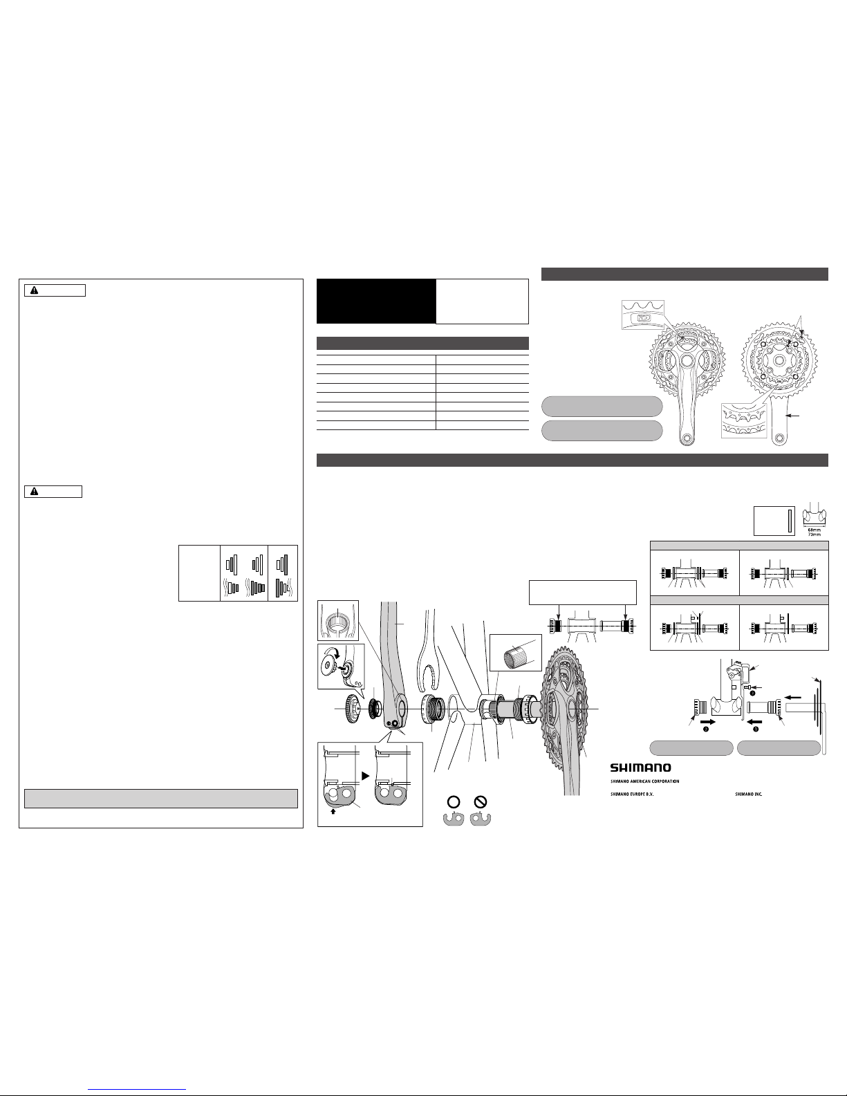
Set so that the “D” symbol on the intermediate chainring is facing outward and so that the tooth numbers on
the largest and smallest chainrings are facing inward, and also so that the projections are aligned with the
crank arm.
Installation of the chainrings
Installation of the Front Chainwheel
■ Follow the procedure in the figure.
1, 2 Use the special tool TL-FC32/33/36 to install the right adapter (counterclockwise thread) and the left adapter
(clockwise thread).
Tightening torque: 35 - 50 N·m {305 - 435 in. lbs.}
Note : Spacers may be necessary depending on the bottom bracket shell width. For details, refer to "Spacer
installation method”.
3 Insert the right crank unit.
4 Set section A of the left crank into the axle of the right crank unit where the groove is wide.
5 Use the TL-FC16/18 to tighten the cap.
Tightening torque: 0.7 - 1.5 N·m {6 - 13 in. lbs.}
6 Push in the stopper plate and check that the plate pin is securely in place, and then tighten the bolt of the left crank
arm. (5 mm Allen key)
Note : Each of the bolts should be evenly and equally tightened to 12 - 14 N·m {106 - 122 in. lbs.}.
FC-M552 / FC-M590-10
42-32-24T
104 mm / 64 mm
50 mm
68, 73 mm
BC1.37 (68, 73 mm)
SM-BB51
CN-HG94 / CN-HG74
Bracket Type
Band Type
Technical Service Instructions SI-1LV0A-002
General Safety Information
Specifications
WARNING
“Maintenance interval depends on the usage and riding circumstances. Clean regularly the
chain with an appropriate chaincleaner. Never use alkali based or acid based solvents such
as rust cleaners. If those solvent be used chain might break and cause serious injury.”
• In order to obtain good gear shifting performance, this chain has a forward side and a reverse side,
and the sides are marked so that the chain will face the correct way when installed. The proper
design performance will be obtained when the chain is installed so that it faces the correct way. If it
is installed so that it faces the opposite way, the chain may come off and the bicycle may fall over
and serious injury may occur as a result.
• The two left crank arm mounting bolts should be tightened alternately in stages rather than each bolt being fully
tightened all at once. Use a torque wrench to check that the final tightening torques are within the range of 12 - 14
N·m. Furthermore, after riding approximately 100 km (60 miles), use a torque wrench to re-check the tightening
torques. It is also important to periodically check the tightening torques. If the tightening torques are too weak or if the
mounting bolts are not tightened alternately in stages, the left crank arm may come off and the bicycle may fall over.
• Before riding, you should carefully check your crankset to make sure that there are no cracks, and if you find any sign
of a crack or any other unusual condition, do NOT use the bicycle.
• Be careful not to let the cuffs of your clothes get caught in the chain while riding, otherwise you may fall off the bicycle.
• Check that the tension of the chain is correct and that the chain is not damaged. If the tension is too weak or the chain
is damaged, the chain should be replaced. If this is not done, the chain may break cause serious injury.
• If the inner cover is not installed correctly, the axle may rust and become damaged, and the bicycle may fall over and
serious injury may occur as a result.
• Obtain and read the service instructions carefully prior to installing the parts. Loose, worn or damaged parts may
cause the bicycle to fall over and serious injury may occur as a result.We strongly recommend only using genuine
Shimano replacement parts.
• Obtain and read the service instructions carefully prior to installing the parts. If adjustments are not carried out
correctly, the chain may come off and this may cause you to fall off the bicycle which could result in serious injury.
• Read these Technical Service Instructions carefully, and keep them in a safe place for later reference.
• If the chain is on the smallest or intermediate chainring, there is the danger of injury from the tips of the teeth on the
largest chainring.
Note
• Make sure that the chainring combination matches the front chainwheel tooth configuration in the Product
specifications table. If other combinations are used, the distance between the chainrings will be incorrect and the chain
might slip off and get caught in between them.
• When the chain is in the position shown in the illustration, the
chain may contact the front chainrings or front derailleur and
generate noise. If the noise is a problem, shift the chain onto the
next-larger rear sprocket or the one after if the chain is in the
position shown in Figure 1. Shift the chain onto the next-smaller
sprocket or the one after if it is in the position shown in Figure 2.
• For frames with suspension, the chain stay angle will vary
depending on whether the bicycle is being ridden or not being
ridden. When the bicycle is not being ridden and the chain is
positioned on the largest/larger chainring and on the smallest sprocket, the chain guide outer plate of the front
derailleur may touch the chain.
• If the bottom bracket shell is not parallel, gear shifting performance will drop.
• Before riding the bicycle, check that there is no play or looseness in the connection. Also, be sure to retighten the crank
arms and pedals at periodic intervals.
• If a squeaking noise is heard coming from the bottom bracket axle and the left crank arm connector, apply grease to
the connector and then tighten it to the specified torque.
• Use a neutral detergent to clean the crank arm and the bottom bracket. Using alkaline or acidic detergents may cause
discoloration.
• If you feel any looseness in the bearings, the bottom bracket should be replaced.
• In addition, if pedaling performance does not feel normal, check this once more.
• Do not wash the bottom bracket with high-pressure jets of water.
• When installing the left and right adapters, be sure to install the inner cover too, otherwise the waterproofing
performance will drop.
• Apply grease to the left and right adapters before installing them.
• If the chain keeps coming off the chainrings during use, replace the chainrings and the chain.
• You should periodically wash the chainrings in a neutral detergent and then lubricate them again. In addition, cleaning
the chain with neutral detergent and lubricating it can be an effective way of extending the useful life of the chainrings
and the chain.
• The cuffs of your clothing may get dirty from the chain while riding.
• When installing the pedals, apply a small amount of grease to the threads to prevent the pedals from sticking. Use a
torque wrench to securely tighten the pedals. Tightening torque:35 - 55 N·m {305 - 479 in. lbs.}. The right-hand crank
arm has a right-hand thread, and the left-hand crank arm has a left-hand thread.
• Parts are not guaranteed against natural wear or deterioration resulting from normal use.
• For maximum performance we highly recommend Shimano lubricants and maintenance products.
• For any questions regarding methods of installation, adjustment, maintenance or operation, please contact a
professional bicycle dealer.
■ Spacer installation method
1 Check whether the width of the bottom bracket shell is 68 mm or
73 mm.
2 Next, install the adapter while referring
to the illustrations below.
Model number
Chainwheel tooth combination
Bolt circle diameter
Chain line
Bottom bracket shell width
Thread dimensions
Applicable bottom bracket
Applicable chain
5
6
2
4
1
3
TL-FC16
TL-FC32
Stopper plate
Plate pin
Push up
Note :
Set the stopper plate in the right
direction as shown in illustration.
One Holland, Irvine, California 92618, U.S.A. Phone: +1-949-951-5003
Industrieweg 24, 8071 CT Nunspeet, The Netherlands Phone: +31-341-272222
3-77 Oimatsu-cho, Sakai-ku, Sakai-shi, Osaka 590-8577, Japan
* Service Instructions in further languages are available at :
http://techdocs.shimano.com
Please note: specifications are subject to change for improvement without notice.(English)
© Apr.2011 by Shimano Inc. XBC IZM Printed in Malaysia.
2.5 mm
Spacer
F
A
73 mm
F
A
68 mm
68 mm
BB mount-type
bracket
73 mm
F
A
F
A
F
A
F
A
F
A
FC-M552
FC-M590-10
Front chainwheel
SI-1LV0A-002-00
Wide groove
area
(A)
Bottom bracket shell
Inner cover
Apply grease to the left and right
adapters before installing them.
For bracket type
Install as shown in the
illustration.
Bolt
AdapterAdapter
Front Derailleur
Front Chainwheel
1,2
Tightening torque :
35 - 50 N·m {305 - 435 in. lbs.}
3
Tightening torque :
5 - 7 N·m {44 - 60 in. lbs.}
Front
chainrings
Fig.1 Fig.2
Rear
sprockets
CAUTION
This front chainwheel is designed for 10-speed systems, and cannot be used in 9speed systems.
Largest chainring/ Intermediate chainring
Tightening torque :
14 - 16 N·m {122 - 139 in. lbs.}
Smallest chainring
Tightening torque :
16 - 17 N·m {139 - 148 in. lbs.}
Mark
Crank arm
Be sure to read the service instructions for the Front Drive System
in conjunction with these service instructions.
 Loading...