

Page 1
Technical Service Instructions SI-1F30D
Front chainwheel
FC-7800
General Safety Information
WARNING
• Be careful not to let the cuffs of your clothes get caught in the chain
while riding, otherwise you may fall off the bicycle.
• Check that the tension of the chain is correct and that the chain is not
damaged. If the tension is too weak or the chain is damaged, the
chain should be replaced. If this is not done, the chain may break and
you may fall off the bicycle.
• Check that there are no cracks in the crank arms before riding the
bicycle. If there are any cracks, the crank arm may break and you
may fall off the bicycle.
• Obtain and read the service instructions carefully prior to installing the
parts. Loose, worn, or damaged parts may cause injury to the rider.
We strongly recommend only using genuine Shimano replacement
parts.
• Read these Technical Service Instructions carefully, and keep them in
a safe place for later reference.
Note
• Make sure that the chainring combination matches the front chainwheel
tooth configuration in the Product specifications table. If other
combinations are used, the distance between the chainrings will be
incorrect and the chain might slip off and get caught in between them.
• When the chain is in the position shown in
the illustration, the chain may contact the
front chainrings or front derailleur and
generate noise. If the noise is a problem,
shift the chain onto the next-larger rear
sprocket or the one after.
• Check that there is no looseness in any
joints or connections before riding the
bicycle. (BB-FC, FC-PD)
• If you feel any looseness in the bottom bracket axle, the bottom
bracket should be replaced.
• In addition, if pedaling performance does not feel normal, check this
once more.
• Do not wash the bottom bracket with high-pressure jets of water.
• Apply grease to the bottom bracket before installing it.
• To ensure the best performance, be sure to use only the specified
type of chain. The wide type of chain cannot be used.
• If the chain keeps coming off the chainrings during use, replace the
chainrings and the chain.
• You should periodically wash the chainrings in a neutral detergent
and then lubricate them again. In addition, cleaning the chain with
neutral detergent and lubricating it can be an effective way of
extending the useful life of the chainrings and the chain.
• Parts are not guaranteed against natural wear or deterioration
resulting from normal use.
• For maximum performance we highly recommend Shimano lubricants
and maintenance products.
• For any questions regarding methods of installation, adjustment,
maintenance or operation, please contact a professional bicycle
dealer.
Front
chainrings
Rear
sprockets
t
Page 2
Specifications
130 mm
A-53 / 42T, B-53 / 39T, B-52 / 39T, B50 / 39T,
54 / 42T, 55 / 42T, 56 / 44T
CN-7800
43.5 mm
B.C. 9/16" x 20T.P.I. (English thread)
165, 167.5, 170, 172.5, 175, 177.5, 180 mmCrank arm length
Pedal threads
Applicable chain
Chain line
Chainwheel tooth combination
Bolt circle diameter
68 mm (1.37 X 24 T.P.I.)
70 mm (M36 X 24 T.P.I.)
Shell width
(Thread dimensions)
S
G
-
X
5
3
-
B
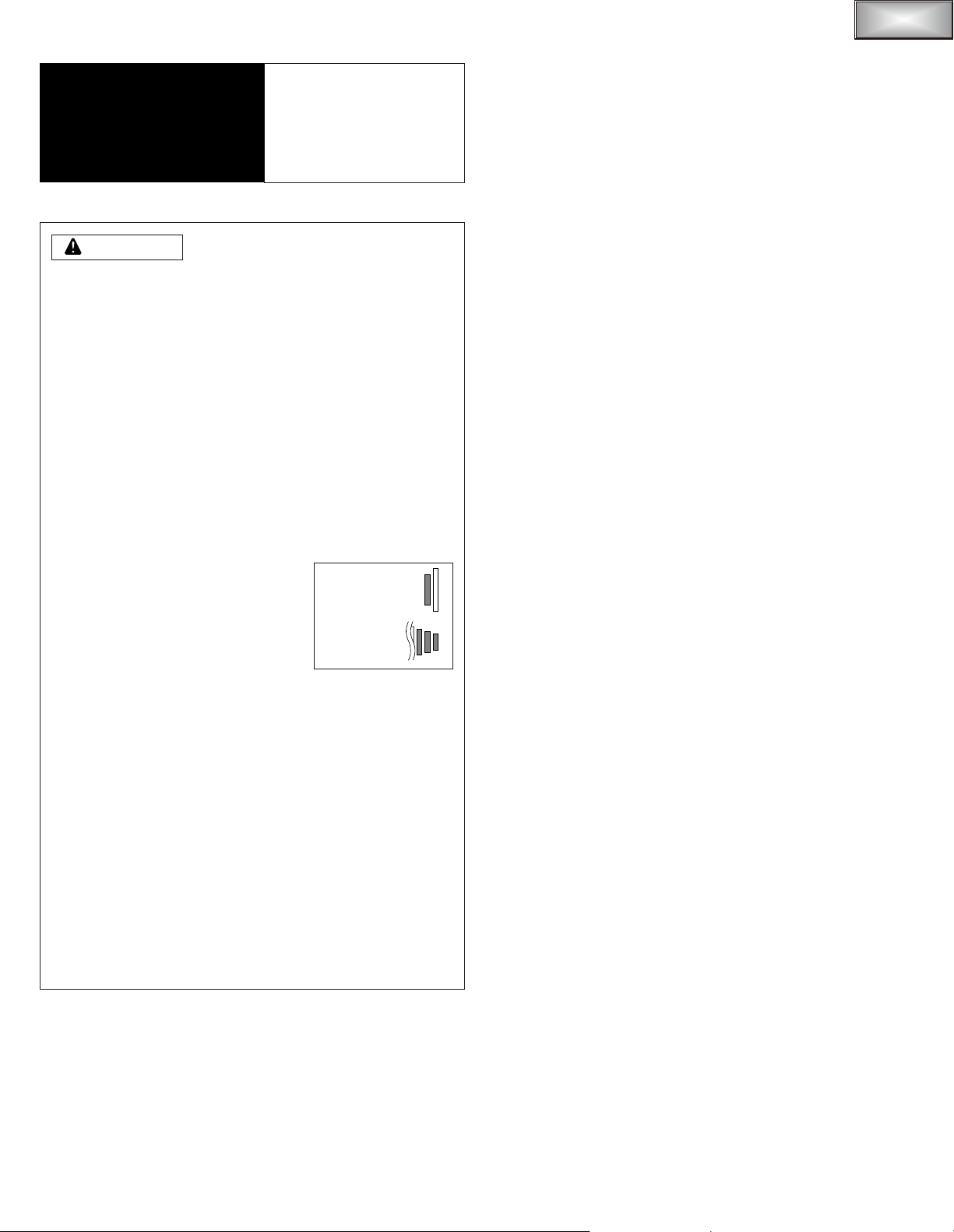
With the marked surface of the larger
chainring facing out, set the larger chainring
so that the chain drop prevention pin is lined
up with the crank arm position.
Chain drop prevention pin
Installation of the chainrings
Smooth shifting will not be possible if the chainrings are incorrectly
installed, so be sure to install the chainrings in the correct positions.
With the marked surface of the smaller
chainring facing away from the crank arm,
set the chainring so that the o mark is
lined up with the crank
arm position.
S
G
-
X
5
3
-
B
Crank arm
S
G
-
X
1
0
S
3
9
-
B
B
D
Crank arm
o mark
Outer side
Inner side
S
G
-
X
1
0
S
3
9
-
B
B
D
Mark
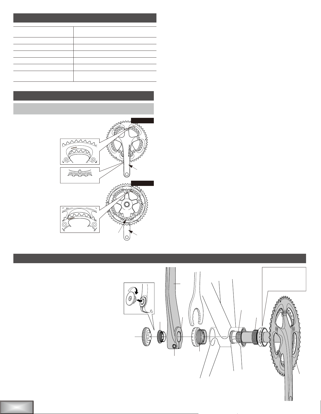
Installation of the front chainwheel
Follow the procedure in the figure.
1, 2 Use the special tool TL-FC32 to install the right
adapter (counterclockwise thread) and the left
adapter (clockwise thread).
Tightening torque: 35 - 50 N·m {305 - 435 in. lbs.}
3 Insert the right crank unit.
4 Set section A of the left crank into the axle of the
right crank unit where the groove is wide.
5 Use the TL-FC16 to tighten the cap.
Tightening torque: 0.7 - 1.5 N·m {6 - 13 in. lbs.}
6 Tighten the bolt of the left crank.
Note : Each of the bolts should be
evenly and equally tightened to
12 - 15 N·m {106 - 132 in. lbs.}.
5
2
4
(A)
1
Wide groove area
TL-FC16
TL-FC32
6
clockwise for 70 mm
[M36] bottom
brackets
t
 Loading...