

Page 1

(English)
DM-E5000-04
Dealer's Manual
ROAD MTB Trekking
City Touring/
Comfort Bike
SC-E6100
SC-E7000
EW-EN100
SW-E6010-L
SW-E7000-L
SW-E6010-R
SW-E7000-R
RD-M8050
MU-UR500
FC-E5000
FC-E5010
FC-E6000
FC-E6010
SM-CRE50
DU-E5000
DU-E5080
SM-DUE10
SM-DUE11
SM-DUE50-T
SM-DUE50-TC
SM-DUE50-C
SM-DUE50-CC
URBAN SPORT E-BIKE
E5000 / E5080 Series
BT-E6000
BT-E6001
BT-E6010
BT-E8010
BT-E8014
BT-E8020
BM-E6000
BM-E6010
BM-E8010
BM-E8020
TL-FC39
TL-FC36
TL-LR15
RT-EM300
RT-EM600
RT-EM800
RT-EM810
RT-EM900
RT-EM910
Page 2

CONTENTS
CONTENTS .................................................................................2
IMPORTANT NOTICE ..................................................................7
TO ENSURE SAFETY ................................................................... 8
LIST OF TOOLS TO BE USED ....................................................13
INSTALLING ELECTRICAL PARTS .............................................15
Names of Parts .....................................................................................15
• Rear carrier mount type ......................................................................................................... 15
• Down tube mount type ......................................................................................................... 16
• Built-in type ............................................................................................................................ 17
Overall Wiring Diagram ....................................................................... 19
Specifications ........................................................................................20
Handling Electric Wires ........................................................................ 20
• Connecting the electric wire .................................................................................................. 21
• Disconnecting the electric wire ............................................................................................. 22
Installing the Cycle Computer/Junction [A] .......................................23
• SC-E6100 .................................................................................................................................. 23
• SC-E7000 .................................................................................................................................. 28
• EW-EN100................................................................................................................................ 29
Installing the Switch Unit .................................................................... 31
• SW-E6010 ................................................................................................................................ 31
• SW-E7000 ................................................................................................................................ 32
Wiring around the Cockpit (SC-E6100) ...............................................34
• Example: Routing the electric wire ....................................................................................... 35
Wiring around the Cockpit (SC-E7000) ...............................................38
• Example: Routing the electric wire ....................................................................................... 39
Wiring around the Cockpit (EW-EN100) .............................................42
• Example: Routing the electric wire ....................................................................................... 43
2
Page 3

Installing the Battery Mount ............................................................... 45
• BM-E6000 ................................................................................................................................ 45
• BM-E6010 ................................................................................................................................ 49
• BM-E8010 ................................................................................................................................ 54
• BM-E8020 ................................................................................................................................ 57
Installing the Speed Sensor and Magnet Unit ................................... 62
• SM-DUE10 ............................................................................................................................... 62
• SM-DUE11 ............................................................................................................................... 64
INSTALLING THE DRIVE UNIT AND PERIPHERAL PARTS .........66
Installing the Drive Unit ......................................................................66
Connecting the Power Cord ................................................................69
• Connection method ............................................................................................................... 69
• Removal method .................................................................................................................... 70
Connecting Cockpit Peripheral Parts and Electronic Gear Shifting
Components .........................................................................................71
Connecting the Speed Sensor .............................................................72
Connecting the Light Cables ...............................................................73
Installing the Drive Unit Cover ............................................................74
• SHIMANO drive unit cover only ............................................................................................. 74
• Used with drive unit cover from other company ................................................................. 76
Installing the Chainring and Crank Arms ...........................................77
Installing the Arm Covers .................................................................... 81
Measuring and Adjusting the Chain Tension ..................................... 83
• Manual adjustment ................................................................................................................ 83
HANDLING THE BATTERY ........................................................84
Installing the Battery ...........................................................................84
• Rear carrier mount type ......................................................................................................... 85
• Down tube mount type ......................................................................................................... 86
• Built-in type ............................................................................................................................ 87
3
Page 4

Removing the Battery .......................................................................... 87
• Rear carrier mount type ......................................................................................................... 88
• Down tube mount type ......................................................................................................... 88
• Built-in type ............................................................................................................................ 89
Charging the Battery ...........................................................................91
• Deep sleep mode .................................................................................................................... 91
• NOTICE .................................................................................................................................... 91
• Charging time ......................................................................................................................... 92
• Charging the battery removed from the bicycle .................................................................. 93
• Charging the battery attached to the bicycle ...................................................................... 95
• Battery charger LED indication .............................................................................................. 96
• Battery LED indication ........................................................................................................... 96
OPERATION AND SETTING ......................................................99
Turning Power ON/OFF ........................................................................ 99
• Operating power from the cycle computer (SC-E6100) ....................................................... 99
• Operating power from the battery ..................................................................................... 100
• Screen display when power is ON ....................................................................................... 101
Basic Operation ..................................................................................102
• Cycle computer and switch unit .......................................................................................... 102
• Junction [A] (EW-EN100) ...................................................................................................... 103
Light ON/OFF ...................................................................................... 104
• SC-E6100 ................................................................................................................................ 105
• EW-EN100.............................................................................................................................. 105
Basic Status Display ...........................................................................106
• SC-E6100/SC-E7000 ............................................................................................................... 106
• EW-EN100.............................................................................................................................. 107
• Battery level indicator .......................................................................................................... 108
Switching the Assist Mode ................................................................ 109
• Switching the assist mode with the switch unit ................................................................. 109
• Switching the assist mode with EW-EN100 ......................................................................... 110
Walk Assist Mode ............................................................................... 110
• Switching to walk assist mode ............................................................................................. 110
• Walk assist mode operation ................................................................................................. 112
Switching Traveling Data Display (SC-E6100) ..................................114
• Resetting the traveling distance .......................................................................................... 116
4
Page 5

Switching Traveling Data Display (SC-E7000) ..................................117
• Resetting the traveling distance .......................................................................................... 119
Switching the Gear Shifting Mode ...................................................120
Setting Menu ...................................................................................... 121
• Startup (SC-E6100) ................................................................................................................ 121
• Startup (SC-E7000) ................................................................................................................ 124
• [Clear] Setting reset .............................................................................................................. 126
• [Clock] Time setting .............................................................................................................. 127
• [Start mode] Start mode setting .......................................................................................... 129
• [Backlight] Backlight setting (SC-E6100) ............................................................................. 130
• [Brightness] Backlight brightness setting (SC-E6100) ......................................................... 131
• [Light] Light ON/OFF (SC-E7000) .......................................................................................... 132
• [Beep] Beep setting .............................................................................................................. 133
• [Unit] km/mile switch ........................................................................................................... 134
• [Language] Language setting .............................................................................................. 135
• [Font color] Font color setting ............................................................................................. 136
• [Adjust] Gear shifting adjustment with the electronic gear shifting unit ........................ 138
• [Shift timing] Automatic gear shifting timing setting ....................................................... 143
• [Shifting advice] Gear shifting advice setting (SC-E6100) .................................................. 144
• [RD protection reset] Reset RD protection ......................................................................... 145
• [Display speed] Adjusting the display speed ...................................................................... 146
• [Exit] Close setting menu screen .......................................................................................... 147
• Updating drive unit backup data ........................................................................................ 147
Setting Mode (EW-EN100) .................................................................148
• RD protection reset .............................................................................................................. 148
• Adjust .................................................................................................................................... 149
Battery LED Error Indications ............................................................152
Cycle Computer Error Messages .......................................................153
• Warnings ............................................................................................................................... 153
• Errors ..................................................................................................................................... 155
• Maintenance alert ................................................................................................................ 157
EW-EN100 Error Indication ................................................................158
CONNECTION AND COMMUNICATION WITH DEVICES .........159
E-TUBE PROJECT .................................................................................159
• Drive unit setting backup function ..................................................................................... 160
5
Page 6

Wireless Function ...............................................................................160
• Functions ............................................................................................................................... 160
• Connection method ............................................................................................................. 160
Items Configurable in E-TUBE PROJECT ............................................ 162
Connecting to a PC ............................................................................. 164
• Connection with a single unit ............................................................................................. 164
• Connection with all SHIMANO STEPS components ............................................................ 165
MAINTENANCE ......................................................................168
Replacing the Clamp Band (SC-E7000) .............................................. 168
Replacing the Chainring ....................................................................169
Replacing the Chain Guard ................................................................ 170
Replacing the Arm Cover ................................................................... 170
6
Page 7
IMPORTANT NOTICE
IMPORTANT NOTICE
• This dealer’s manual is intended primarily for use by professional bicycle mechanics.
Users who are not professionally trained for bicycle assembly should not attempt to
install the components themselves using the dealer’s manuals.
If any part of the information on the manual is unclear to you, do not proceed with the
installation. Instead, contact your place of purchase or a bicycle dealer for their
assistance.
• Make sure to read all instruction manuals included with the product.
• Do not disassemble or modify the product other than as stated in the information
contained in this dealer’s manual.
• All dealer’s manuals and instruction manuals can be viewed on-line on our website
(https://si.shimano.com).
• For consumers who do not have easy access to the internet, please contact a SHIMANO
distributor or any of the SHIMANO offices to obtain a hardcopy of the User's Manual.
• Please observe the appropriate rules and regulations of the country, state or region in
which you conduct your business as a dealer.
®
• The Bluetooth
Bluetooth SIG, Inc., and are used under agreement by SHIMANO INC. Other trademarks
and product names belong to their respective owners.
-compatible wordmark and logo are registered trademarks owned by
For safety, be sure to read this dealer’s manual thoroughly before use, and
follow it for correct use.
The following instructions must be observed at all times in order to prevent personal injury
and physical damage to equipment and surroundings. The instructions are classified
according to the degree of danger or damage which may occur if the product is used
incorrectly.
DANGER
WARNING
CAUTION
Failure to follow the instructions will result in death or serious injury.
Failure to follow the instructions could result in death or serious
injury.
Failure to follow the instructions could cause personal injury or
physical damage to equipment and surroundings.
7
Page 8

TO ENSURE SAFETY
TO ENSURE SAFETY
DANGER
Be sure to also inform users of the following:
Handling the battery
• Do not deform, modify, disassemble, or apply solder directly to the battery. Doing so may
cause leakage, overheating, bursting, or ignition.
• Do not leave the battery near sources of heat such as heaters, and do not heat the
battery or throw it into a fire. Doing so may cause bursting or ignition.
• Do not throw or subject the battery to strong shock. Doing so may cause it to overheat,
burst, or ignite.
• Do not place the battery into fresh water or sea water, and do not allow the battery
terminals to get wet. Doing so may cause overheating, bursting, or ignition.
• Use the specified battery charger when charging and observe the specified charging
conditions. Doing otherwise may cause it to overheat, burst, or ignite.
WARNING
• Be sure to follow the instructions provided in the manuals when installing the product.
It is recommended to use genuine SHIMANO parts only. If parts such as bolts and nuts
become loose or damaged, the bicycle may suddenly fall over, which may cause serious
injury.
In addition, if adjustments are not carried out correctly, problems may occur, and the
bicycle may suddenly fall over, which may cause serious injury.
•
• For information on products not explained in this manual, refer to the manuals provided
Be sure to wear safety glasses or goggles to protect your eyes while performing
maintenance tasks such as replacing parts.
with each product.
• After reading the dealer's manual thoroughly, keep it in a safe place for later reference.
Be sure to also inform users of the following:
• Be careful not to let yourself be distracted by the cycle computer display while riding the
bicycle. Otherwise, you may fall off the bicycle.
8
Page 9

TO ENSURE SAFETY
• Before riding, check that the wheels are secured. Otherwise, you may fall off the bicycle
and be seriously injured.
• Be sufficiently familiar with how to start the power assisted bicycle before riding on busy
streets. Otherwise, you may start the bicycle unexpectedly, which may result in an
accident.
• Make sure that the light is on when riding at night.
• Do not disassemble the product. Disassembling may cause injury.
• When charging the battery while it is installed on the bicycle, do not move the bicycle.
The charger’s power plug may come loose and not be fully inserted into the electrical
outlet, resulting in risk of fire.
• Do not inadvertently touch the drive unit when it has been continuously used for a long
period of time. The surface of the drive unit becomes hot and could cause burns.
Lithium ion battery
• If any liquid leaking from the battery gets into your eyes, immediately wash the affected
area thoroughly with clean water such as tap water without rubbing your eyes, and seek
medical attention immediately. If this is not done, the battery liquid may damage your
eyes.
• Do not recharge the battery in very humid places or outdoors. Doing so may result in
electric shock.
• Do not insert or remove the plug while it is wet. Doing so may result in electric shock. If
the inside of the plug is wet, dry it thoroughly before inserting it.
• If the battery does not become fully charged after 2 hours of charging, immediately
unplug the battery from the outlet and contact the place of purchase. Doing otherwise
may cause overheating, bursting, or ignition of the battery.
• Do not use the battery if it has any noticeable scratches or other external damage. If this
is not observed, bursting, overheating, or problems with operation may occur.
• The operating temperature ranges for the battery are given below. Do not use it in
temperatures outside these ranges. If it is used or stored in temperatures which are
outside these ranges, fire, injury, or problems with operation may occur.
1. During discharge: -10°C - 50°C
2. During charging: 0°C - 40°C
Bicycle installation and maintenance:
• Be sure to remove the battery and charging cable before wiring or attaching parts to the
bicycle. Otherwise, an electric shock may result.
9
Page 10

TO ENSURE SAFETY
• Intervals between maintenance depend on the use and riding circumstances. Clean the
chain with an appropriate chain cleaner regularly. Never use alkali based or acid based
solvents, such as rust cleaners. If these solvents are used the chain might break and cause
serious injury.
CAUTION
Be sure to also inform users of the following:
• Observe the instructions in the user's manual for the bicycle in order to ride safely.
• Periodically check the battery charger and adapter—particularly the cord, plug, and
case—for any damage. If the charger or adapter is broken, do not use it until it has been
repaired.
• Use the product according to the directions for use or those of a safety supervisor. Do not
allow physically, sensory, or mentally impaired persons, inexperienced persons, or persons
without required knowledge, including children, to use this product.
• Do not allow children to play near the product.
• If any malfunction or trouble occurs, consult the place of purchase.
• Never modify the system as this may cause a malfunction in the system.
Lithium ion battery
• Do not leave the battery in a place exposed to direct sunlight, inside a vehicle on a hot
day, or other hot places. This may result in battery leakage.
• If any leaked fluid gets on your skin or clothes, wash it off immediately with clean water.
The leaked fluid may damage your skin.
• Store the battery in a safe place away from the reach of infants and pets.
NOTICE
Be sure to also inform users of the following:
• Be sure to attach dummy plugs to any unused ports.
• For installation and adjustment of the product, consult a dealer.
• The components are designed to be fully waterproof and withstand wet weather riding
conditions; however, do not deliberately place them into water.
• Do not clean the bicycle with a high-pressure wash. If water gets into any of the
components, operating problems or rusting may result.
10
Page 11

TO ENSURE SAFETY
• Handle the components carefully, and avoid subjecting them to strong shock.
• Do not turn the bicycle upside down. There is a risk of damage to the cycle computer and
shift switches.
• Although the bicycle still functions as a normal bicycle even when the battery is removed,
the light will not turn on if it is connected to the electric power system. Be aware that
using the bicycle under these conditions will be considered non-observance of the road
traffic laws in Germany.
• When carrying the bicycle in a car, remove the battery from the bicycle and place it on a
stable surface in the car.
• Before connecting the battery, make sure that there is no water collecting in the area
where the battery will be connected (connector), and that it is not dirty.
• When charging the battery while it is mounted on the bicycle, be careful of the
following:
– Before charging, check that there is no water on the charging port of the charging
plug.
– Check that the battery mount is locked before charging.
– Do not remove the battery from the battery mount while charging.
– Do not ride with the charger mounted.
– Close the cap on the charging port when not charging.
– Fix the bicycle in place when charging, so that it does not tip over.
• It is recommended to use a SHIMANO genuine battery. If using a battery from another
company, be sure to read the product manual thoroughly prior to use.
• Some of the important information in this dealer's manual can also be found on the
device labels.
• The number written on the battery is necessary when purchasing spare keys for the
battery lock. Store it carefully.
• Use a damp, well wrung out cloth when cleaning the battery and plastic cover.
• If you have any questions about the use and maintenance of the product, consult the
place of purchase.
• Contact the place of purchase for updates to the component software. The most up-to-
date information is available on the SHIMANO website. For details, refer to the
"CONNECTION AND COMMUNICATION WITH DEVICES" section.
• Products are not guaranteed against natural wear and deterioration from normal use
and aging.
11
Page 12
TO ENSURE SAFETY
• For maximum performance we highly recommend SHIMANO lubricants and maintenance
products.
Connection and communication with PC
Using a PC linkage device to connect a PC to your bicycle (system or component) allows
you to use E-TUBE PROJECT to perform a range of tasks, such as customizing individual
components or the entire system, or updating firmware.
• PC linkage device: SM-PCE1 / SM-PCE02
• E-TUBE PROJECT: PC application
• Firmware: Software inside each component
Connection and communication with smartphone or tablet
Connecting your bicycle (system or component) over Bluetooth® LE to a smartphone or
tablet allows you to use the smartphone/tablet version of E-TUBE PROJECT to perform a
range of tasks, such as customizing individual components or the entire system, or
updating firmware.
• E-TUBE PROJECT: Application for smartphones/tablets
• Firmware: Software inside each component
Disposal information for countries outside the European Union
This symbol is only valid within the European Union.
Follow local regulations when disposing of used batteries. If you are not
sure, consult the place of purchase or distributor.
The actual product may differ from illustrations, as this manual is intended
mainly to explain the procedures for using the product.
12
Page 13
LIST OF TOOLS TO BE USED
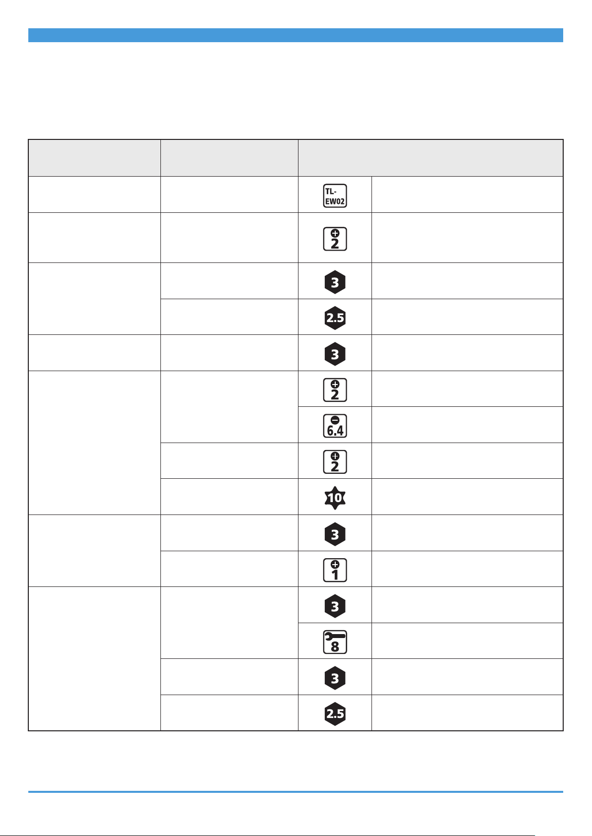
LIST OF TOOLS TO BE USED
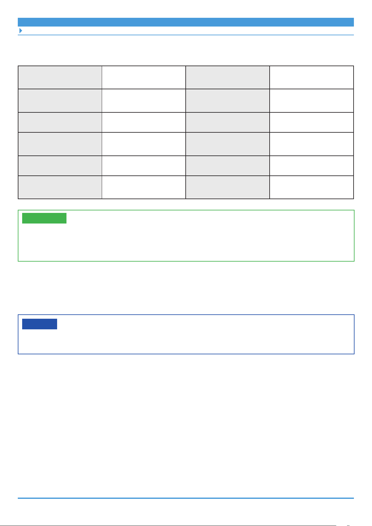
The following tools are needed for installation/removal, adjustment, and maintenance
purposes.
Component
Electric wire Plug TL-EW02
Cycle Computer
(SC-E6100)
Cycle Computer
(SC-E7000)
Switch unit Clamp bolt
Battery mount
(BM-E6000)
Location used/bolt
type
Clamp bolt
Mounting bolt
Angle adjustment bolt
Clamp bolt
Case fixing bolt
Key unit
Mount lower case
Tool
Screwdriver [#2]
3 mm hexagon wrench
2.5 mm hexagon wrench
3 mm hexagon wrench
Screwdriver [#2]
Slotted screwdriver (6.4 mm)
Screwdriver [#2]
Battery mount
(BM-E6010)
Battery mount
(BM-E8010)
Mount upper case
Mount lower case
Key unit
Key unit cover
Mount upper case
Mount lower case
Key unit
Key unit cover
Mount upper case
Hexalobular [#10]
3 mm hexagon wrench
Screwdriver [#1]
3 mm hexagon wrench
8 mm spanner
3 mm hexagon wrench
2.5 mm hexagon wrench
13
Page 14
LIST OF TOOLS TO BE USED
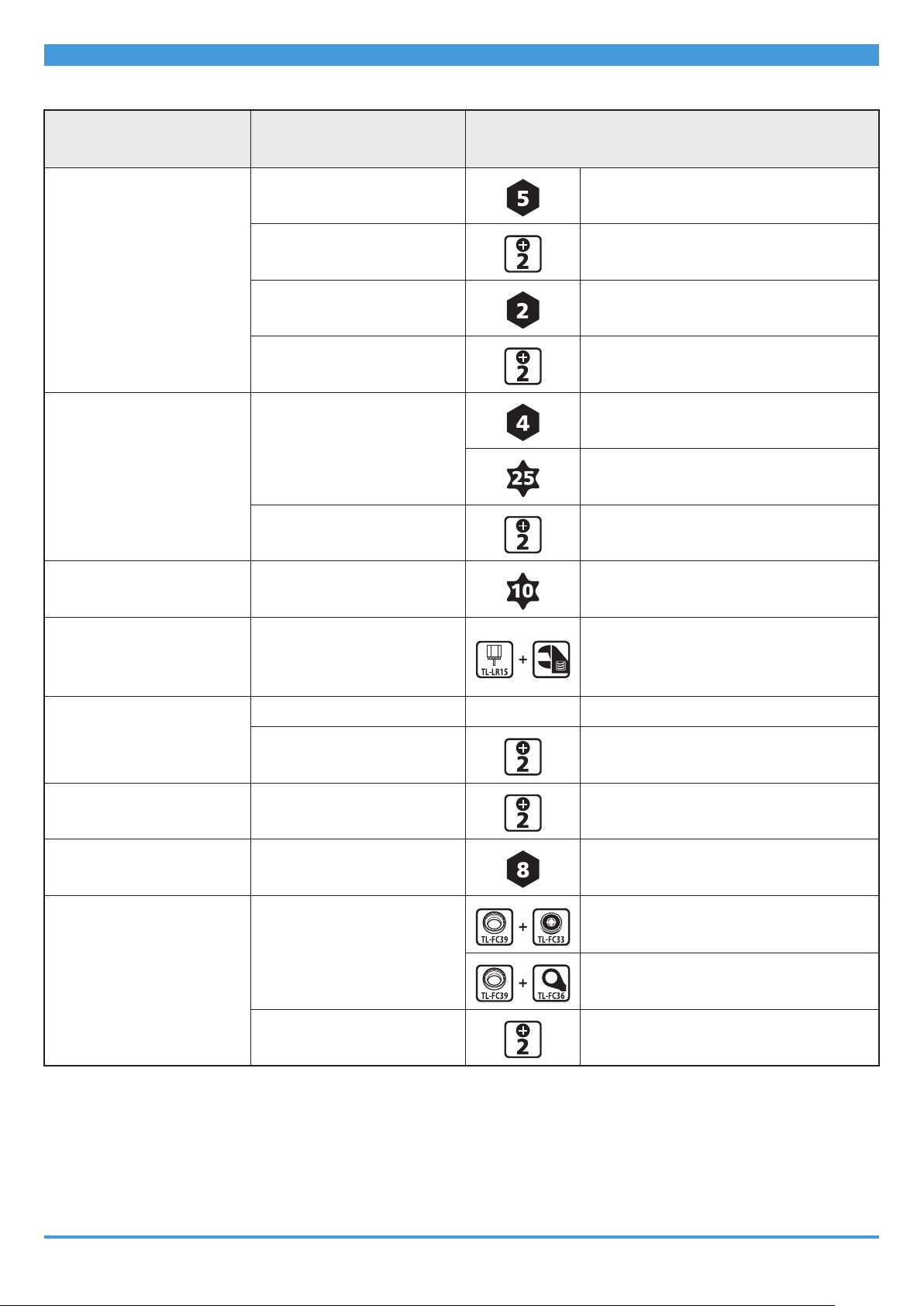
Component
Battery mount
(BM-E8020)
Speed sensor
(SM-DUE10)
Speed sensor
(SM-DUE11)
Location used/bolt
type
Mount lower case
Key unit
Mount upper case
Key cylinder
Key unit cover
Speed sensor mounting
bolt
Magnet unit mounting
bolt
Speed sensor mounting
bolt
Tool
5 mm hexagon wrench
Screwdriver [#2]
2 mm hexagon wrench
Screwdriver [#2]
4 mm hexagon wrench
Hexalobular [#25]
Screwdriver [#2]
Hexalobular [#10]
Disc brake rotor
(Listed in this manual as
rotor from here on out)
Drive unit mounting bolt
Drive Unit
Light cable Light cable mounting bolt
Crank arm Crank arm mounting bolt
Chainring
Lock ring
Drive unit cover
Lock ring
Chain guard
Arm cover
TL-LR15 + adjustable wrench
-
Contact the bicycle manufacturer.
Screwdriver [#2]
Screwdriver [#2]
8 mm hexagon wrench
TL-FC39 + TL-FC33
TL-FC39 + TL-FC36
Screwdriver [#2]
14
Page 15
INSTALLING ELECTRICAL PARTS
Names of Parts
INSTALLING ELECTRICAL PARTS
Names of Parts
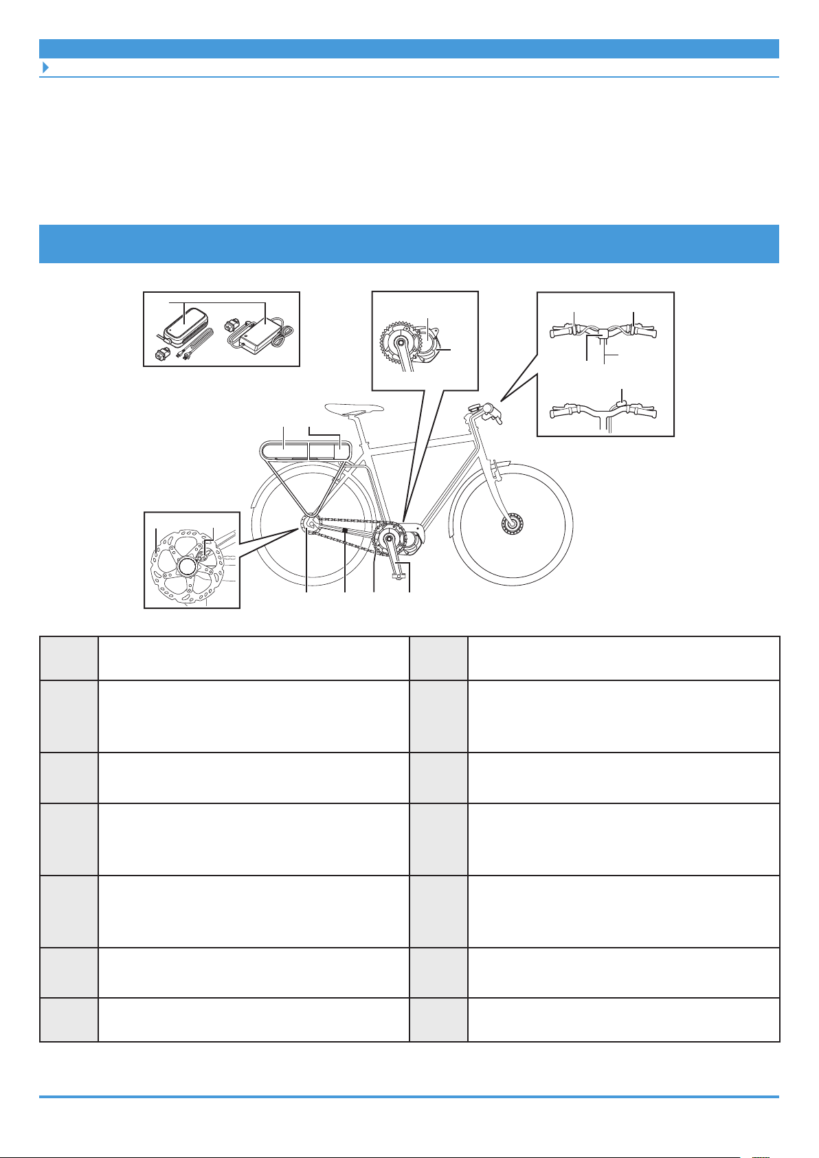
Rear carrier mount type
(A)
(C)
(P)
(A) (B)
(J)
Battery: BT-E6000 / BT-E6001
Drive unit: DU-E5000 / DU-E5080
(I)
(H)
(G)
(F)
(E)
(C)
(B)
(D)
(K)
(D)
(N)
Battery mount: BM-E6000
Drive unit cover:
SM-DUE50-C / SM-DUE50-CC /
SM-DUE50-T / SM-DUE50-TC
(L)
(M)
(O)
(E)
(G)*1
(I)*1
(K)
(M)
Crank arm:
FC-E5000 / FC-E5010 / FC-E6000 / FC-E6010
Speed sensor: SM-DUE10
Speed sensor: SM-DUE11
Switch unit (default: assist switch):
SW-E6010-L / SW-E7000-L
Electric wire: EW-SD50
15
(F)
(H)*2
(J)
(L)*2
(N)*3
Chainring: SM-CRE50
Motor unit (internal geared hub DI2):
MU-UR500
Rear derailleur (DI2): RD-M8050
Rotor:
RT-EM300 / RT-EM600 / RT-EM800 /
RT-EM810 / RT-EM900 / RT-EM910
Switch unit (default: shift switch):
SW-E6010-R / SW-E7000-R
Cycle computer: SC-E6100 / SC-E7000
Page 16
INSTALLING ELECTRICAL PARTS
Names of Parts
(O)*3
*1 Use either (G) or (I). (I) is only when (J) disc brake is mounted.
*2 Electronic gear shifting only.
*3 Use either (N) or (O).
Junction [A] (wireless unit): EW-EN100
(P)
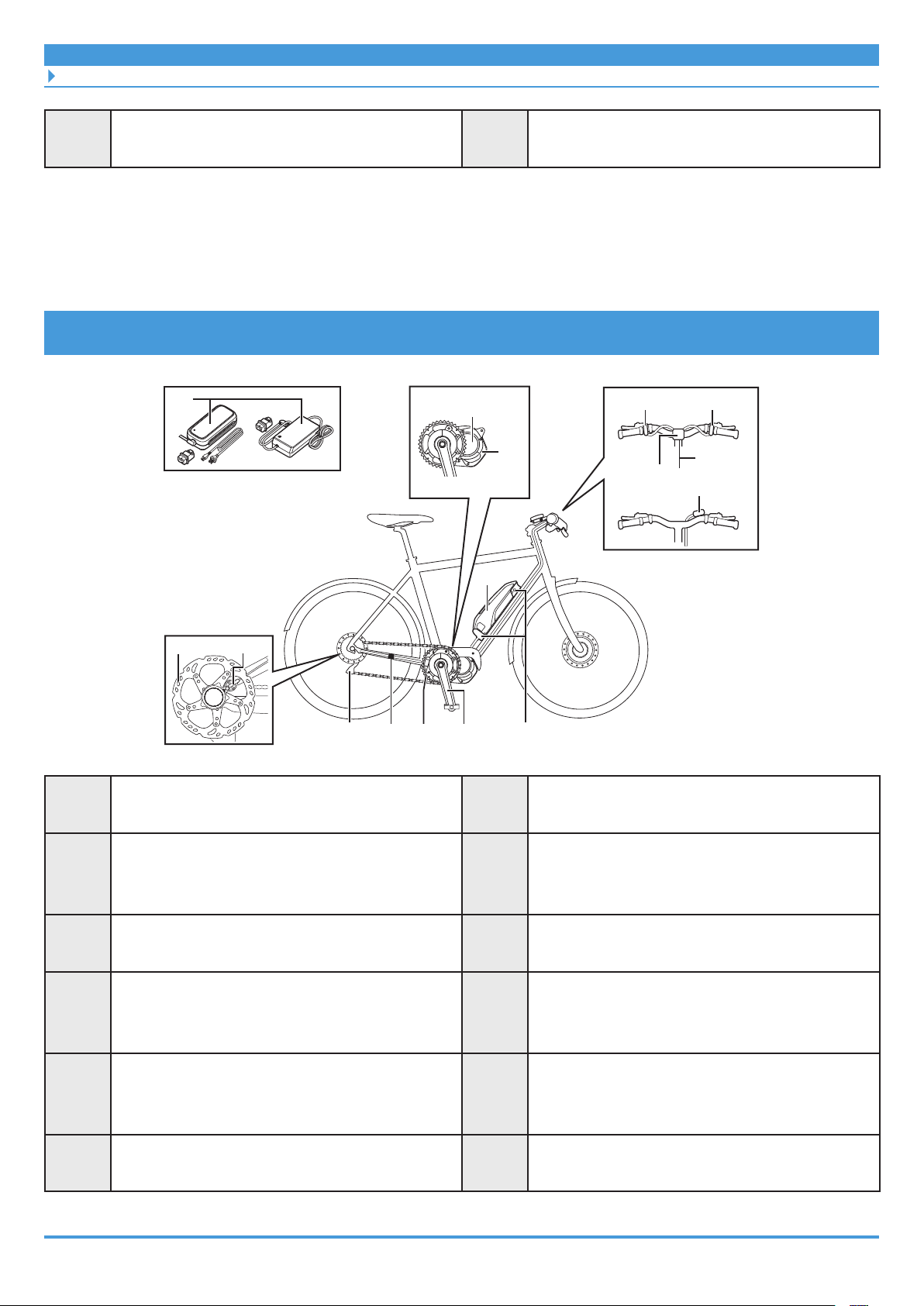
Down tube mount type
(P)
(C)
(A)
Battery charger:
EC-E6000 / EC-E6002+SM-BCC1
(K)
(D)
(N)
(L)
(M)
(O)
(A)
(C)
(E)
(G)*1
(I)*1
(J)
Battery:
BT-E6010 / BT-E8010 / BT-E8014
Drive unit: DU-E5000 / DU-E5080
Crank arm:
FC-E5000 / FC-E5010 / FC-E6000 / FC-E6010
Speed sensor: SM-DUE10
Speed sensor: SM-DUE11
(I)
(H)
(G)
(F)
(E) (B)
(B)
(D)
(F)
(H)*2
(J)
Battery mount: BM-E6010 / BM-E8010
Drive unit cover:
SM-DUE50-C / SM-DUE50-CC /
SM-DUE50-T / SM-DUE50-TC
Chainring: SM-CRE50
Motor unit (internal geared hub DI2):
MU-UR500
Rear derailleur (DI2): RD-M8050
Rotor:
RT-EM300 / RT-EM600 / RT-EM800 /
RT-EM810 / RT-EM900 / RT-EM910
(K)
Switch unit (default: assist switch):
SW-E6010-L / SW-E7000-L
16
(L)*2
Switch unit (default: shift switch):
SW-E6010-R / SW-E7000-R
Page 17
INSTALLING ELECTRICAL PARTS
Names of Parts
(M)
(O)*3
*1 Use either (G) or (I). (I) is only when (J) disc brake is mounted.
*2 Electronic gear shifting only.
*3 Use either (N) or (O).
Electric wire: EW-SD50
Junction [A] (wireless unit): EW-EN100
(N)*3
(P)
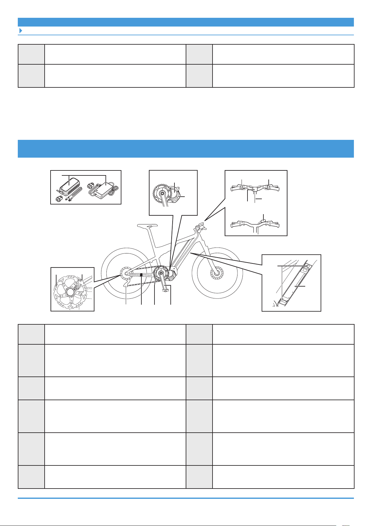
Built-in type
(P)
(C)
(D)
Cycle computer: SC-E6100 / SC-E7000
Battery charger:
EC-E6000 / EC-E6002+SM-BCC1
(K)
(N)
(L)
(M)
(O)
(A)
(C)
(E)
(G)*1
(I)*1
(J)
Battery: BT-E8020
Drive unit: DU-E5000 / DU-E5080
Crank arm:
FC-E5000 / FC-E5010 / FC-E6000 / FC-E6010
Speed sensor: SM-DUE10
Speed sensor: SM-DUE11
(I)
(H)
(G)
(F)
(E)
(B)
(D)
(F)
(H)*2
(J)
(B)
(A)
Battery mount: BM-E8020
Drive unit cover:
SM-DUE50-C / SM-DUE50-CC /
SM-DUE50-T / SM-DUE50-TC
Chainring: SM-CRE50
Motor unit (internal geared hub DI2):
MU-UR500
Rear derailleur (DI2): RD-M8050
Rotor:
RT-EM300 / RT-EM600 / RT-EM800 /
RT-EM810 / RT-EM900 / RT-EM910
(K)
Switch unit (default: assist switch):
SW-E6010-L / SW-E7000-L
17
(L)*2
Switch unit (default: shift switch):
SW-E6010-R / SW-E7000-R
Page 18

INSTALLING ELECTRICAL PARTS
Names of Parts
(M)
(O)*3
*1 Use either (G) or (I). (I) is only when (J) disc brake is mounted.
*2 Electronic gear shifting only.
*3 Use either (N) or (O).
Electric wire: EW-SD50
Junction [A] (wireless unit): EW-EN100
(N)*3
(P)
Cycle computer: SC-E6100 / SC-E7000
Battery charger:
EC-E6000 / EC-E6002+SM-BCC1
18
Page 19
INSTALLING ELECTRICAL PARTS
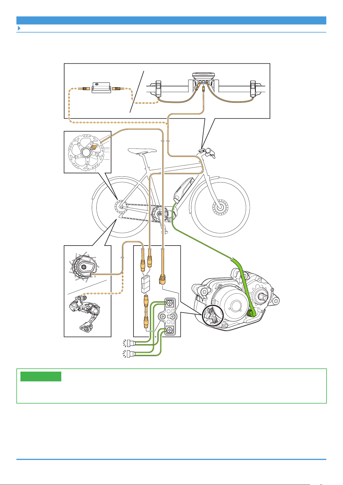
Overall Wiring Diagram
Overall Wiring Diagram
EW-EN100
TECH TIPS
• The maximum cable length of the electric wire (EW-SD50) is 1,600 mm.
19
Page 20
INSTALLING ELECTRICAL PARTS
Specifications
Specifications
Operating temperature
range: Discharging
Operating temperature
range: Charging
Storage temperature
Storage temperature
(battery)
Charging voltage
Charging time
-10 - 50°C
0 - 40°C
-20 - 70°C
-20 - 60°C
100 - 240 V AC
Refer to the battery
charger user's manual.
Battery type
Nominal capacity
Rated voltage
Drive Unit
Motor type
Rated drive unit power
Lithium ion battery
Refer to the battery
user's manual.
36 V DC
Midship
Brushless DC
250 W
TECH TIPS
• The maximum speed provided by assist is set by the manufacturer, but may vary depending
on the conditions under which the bicycle is used.
• The latest manual information can be accessed on our website (https://si.shimano.com).
Handling Electric Wires
Be sure to use the SHIMANO original tool to remove and insert electric wires.
NOTICE
• When connecting and disconnecting electric wires, do not forcibly bend the plug part. It
may result in a poor connection.
20
Page 21
INSTALLING ELECTRICAL PARTS
Handling Electric Wires
Connecting the electric wire
Connect the electric wire to the E-TUBE port.
1. Set the plug part of the electric wire to the SHIMANO original tool.
If there is a protrusion on the plug part of the electric wire, set it aligned with the groove
on the SHIMANO original tool.
No protrusion on plug Protrusion on plug
2. Insert the plug part on the electric wire into the E-TUBE port.
Push it straight in until you feel it click into place.
Plug
E-TUBE port
21
Page 22
INSTALLING ELECTRICAL PARTS
Handling Electric Wires
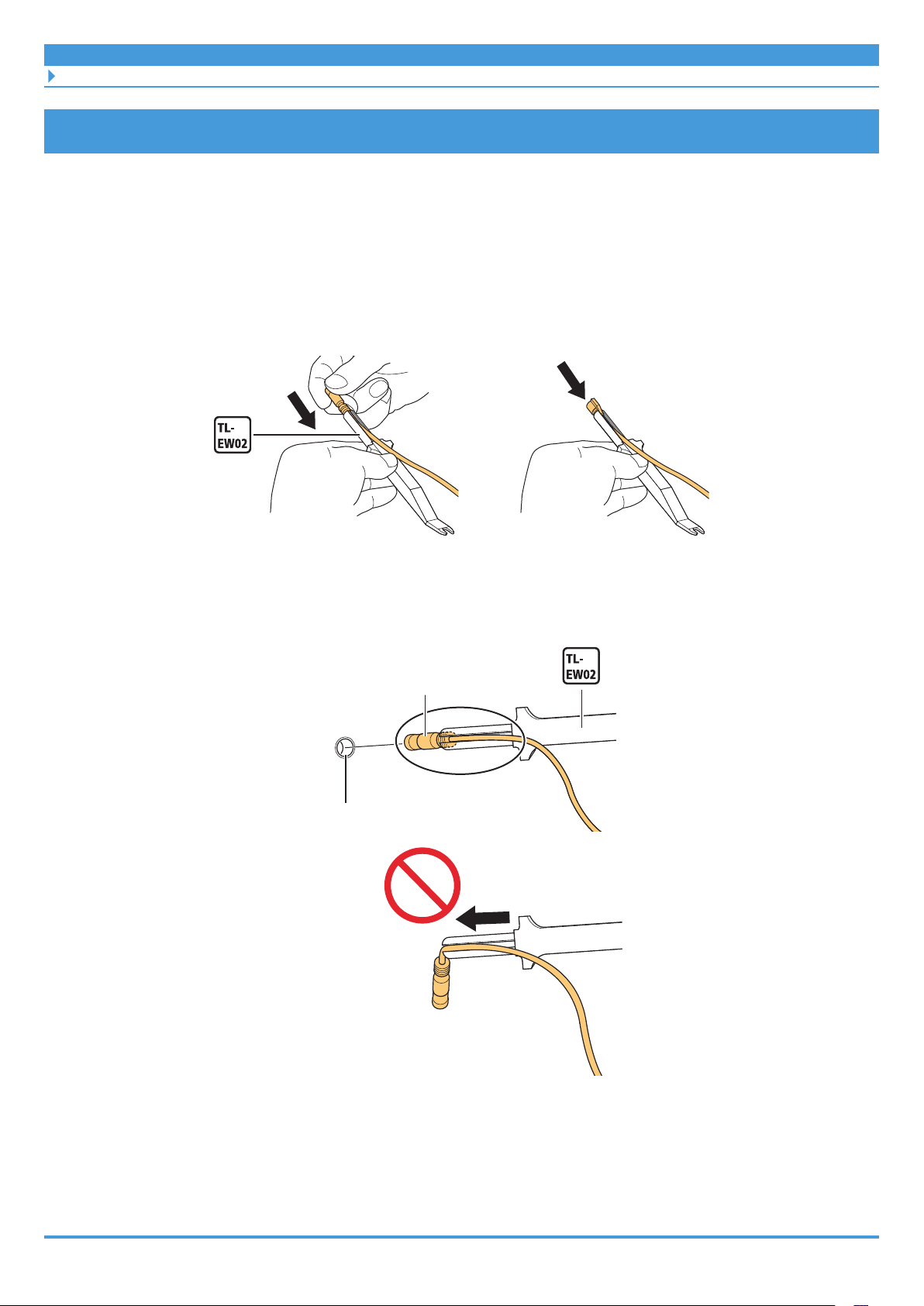
Disconnecting the electric wire
1. Disconnect the electric wire.
(1) Insert the SHIMANO original tool into the plug part of the electric wire.
(2) Disconnect the electric wire from the E-TUBE port.
* As shown in the figure, move the SHIMANO original tool like a lever with part (A) as the
axis to disconnect. If there is limited space to insert the tool, lift the SHIMANO original
tool straight up and disconnect the electric wire.
(1) (2)
(A)
22
Page 23
INSTALLING ELECTRICAL PARTS
Installing the Cycle Computer/Junction [A]
Installing the Cycle Computer/Junction [A]
SC-E6100
The bracket used to secure the cycle computer to the handlebar, and the cycle computer itself
are separate parts.
` Installing the bracket and cycle computer
1. Check the diameter of the handlebar to determine whether adapters
are needed, and then select the clamp bolt.
øA øB-øA Bracket Clamp bolt
23.4-24 0-1.1 Required Length: 15.5 mm
24-25.5 0-1.1 Required Length: 20 mm
31.3-31.9 0-0.6 Not necessary Length: 20 mm
øB
øA
25
30
Handlebar
2. If adapters are required, push them along to the center of the
handlebar.
Handlebar
Adapter
23
Page 24
INSTALLING ELECTRICAL PARTS
Installing the Cycle Computer/Junction [A]
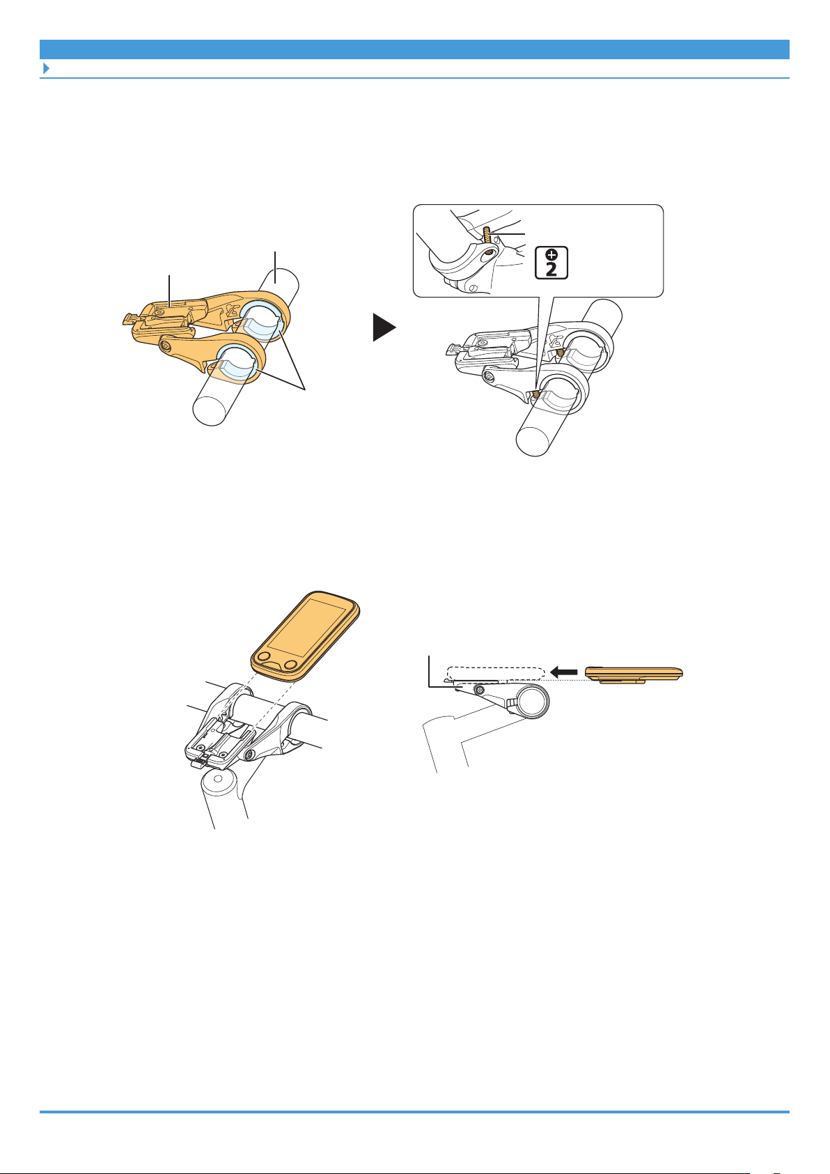
3. Temporarily install the bracket.
(1) Push the clamp area open, and then install the bracket to the center of the handlebar.
(2) Temporarily install the clamp bolt (of the length selected in step 1).
Handlebar
Bracket
Adapter
4. Install the cycle computer to the bracket.
Slide the cycle computer and install it to the bracket.
Insert it firmly until you hear it click.
Clamp bolt
(Temporary)
Bracket
24
Page 25
INSTALLING ELECTRICAL PARTS
Installing the Cycle Computer/Junction [A]
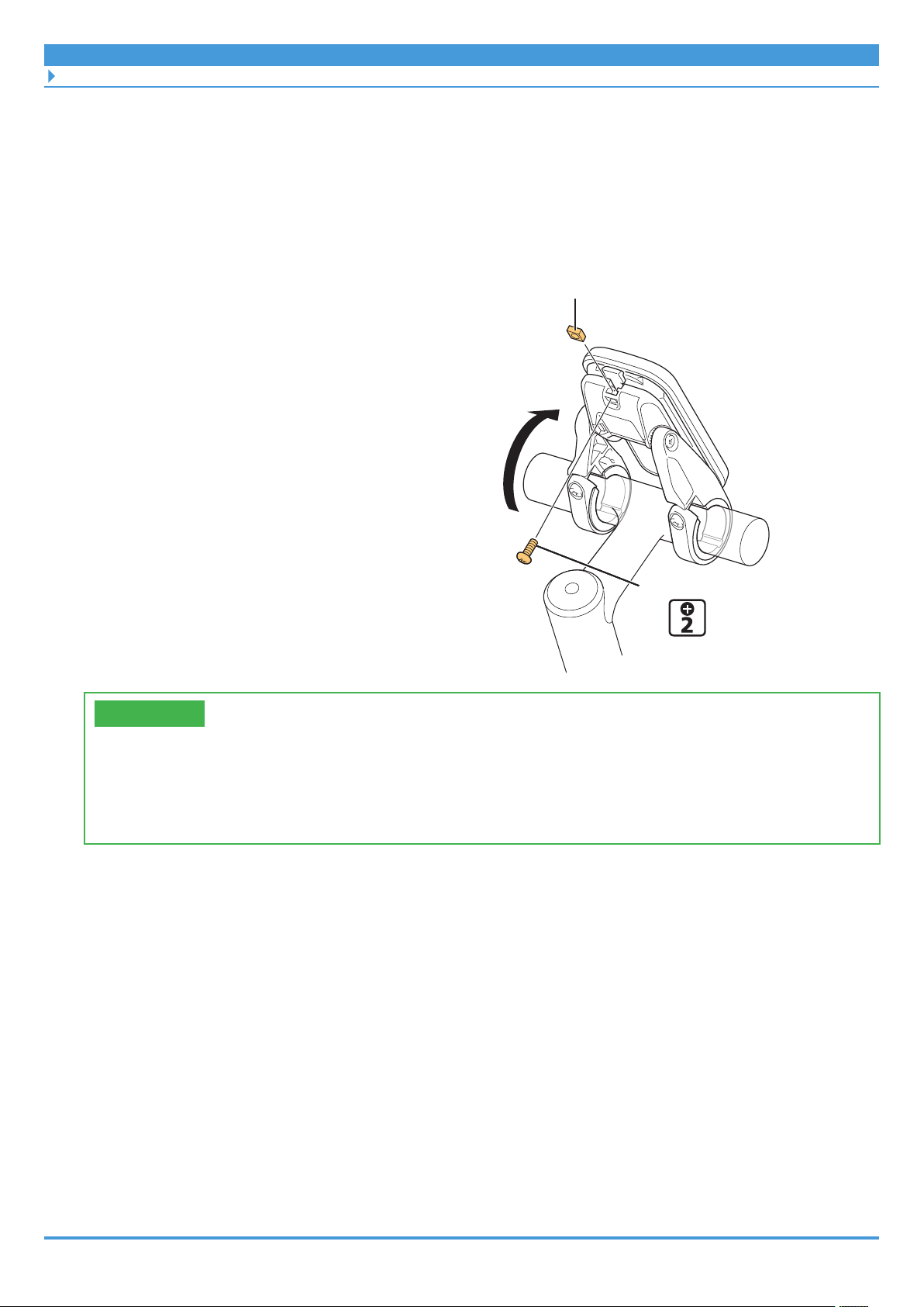
5. Secure the cycle computer if necessary.
If the cycle computer will not be secured to the bracket, this step is not necessary.
(1) Stand the cycle computer and bracket up on the stem (as though you are turning the
cycle computer around).
(2) Insert the square nut into the bracket.
(2)
(3) Tighten the mounting bolt.
(1)
Square nut
Mounting bolt
(3)
0.4 - 0.5 N·m
TECH TIPS
• This procedure is used to secure the cycle computer to the bracket, so that it cannot
be easily removed. This is useful for displaying the product.
• Ask the user if they will secure the cycle computer when the product is delivered. If
necessary, explain how to do as (as described above).
25
Page 26
INSTALLING ELECTRICAL PARTS
Installing the Cycle Computer/Junction [A]
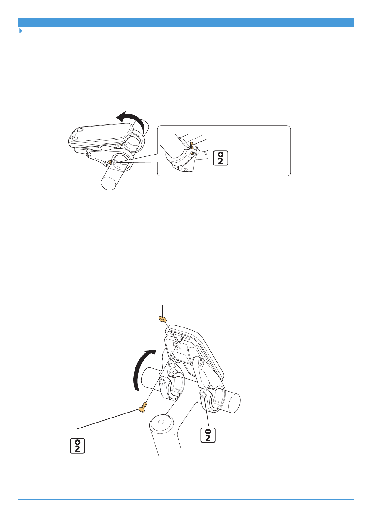
6. Secure the bracket to the handlebar.
(1) Return the cycle computer to its installation position if the cycle computer was stood
up on the stem in step 5.
(2) Secure the bracket.
(1)
(2)
Clamp bolt
1 N·m
` Removing the cycle computer
1. Remove the mounting bolt on the bottom side of the bracket.
If the cycle computer was not secured, this procedure is not necessary. Skip to step 2.
(1) Loosen the clamp bolt, and then stand the cycle computer and bracket up on the stem
(as though you are turning the cycle computer around).
(2) Remove the mounting bolt and square nut.
(2)
Square nut
(1)
Mounting bolt(2)
0.4 - 0.5 N·m
Clamp bolt(1)
26
Page 27
INSTALLING ELECTRICAL PARTS
Installing the Cycle Computer/Junction [A]
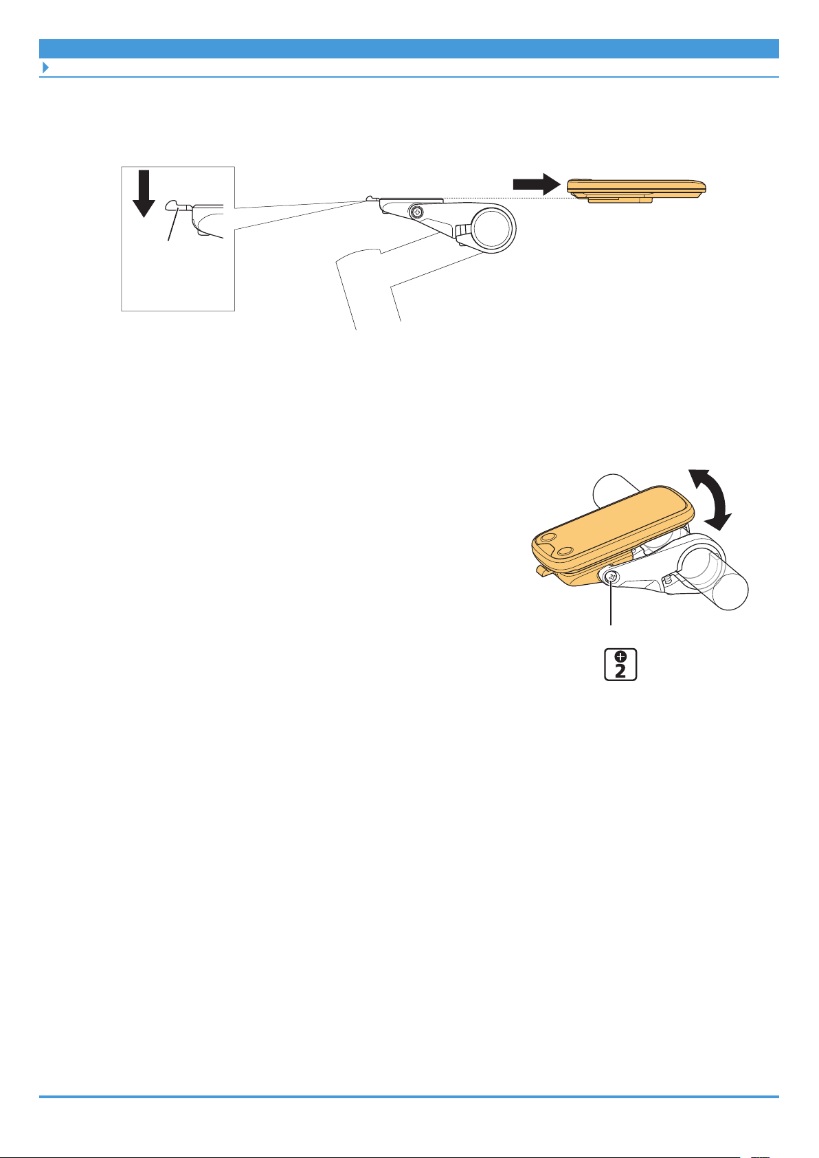
2. Remove the cycle computer from the bracket.
Slide the cycle computer to the front while pushing the bracket lever down to remove it.
Lever
` Adjusting the installation angle
1. Adjust the installation angle of the cycle computer.
(1) Loosen the angle adjustment bolt.
(2) After adjusting the angle of the cycle computer to
make it easier to see while riding, tighten the
angle adjustment bolt.
Angle adjustment bolt
0.5 N·m
27
Page 28
INSTALLING ELECTRICAL PARTS
Installing the Cycle Computer/Junction [A]
SC-E7000
1. Pass the cycle computer’s clamp band around the handlebar.
Clamp band
Handlebar
Cycle Computer
2. Adjust the installation angle of the cycle computer.
As shown in the figure, adjust the cycle computer to an angle that is visible when riding,
and then tighten the clamp bolt to secure it in place.
* A display angle between 15° and 35° from the horizontal surface is recommended.
Clamp bolt
35°
15°
Front of bicycle
0.8 N·m
28
Page 29
INSTALLING ELECTRICAL PARTS
Installing the Cycle Computer/Junction [A]
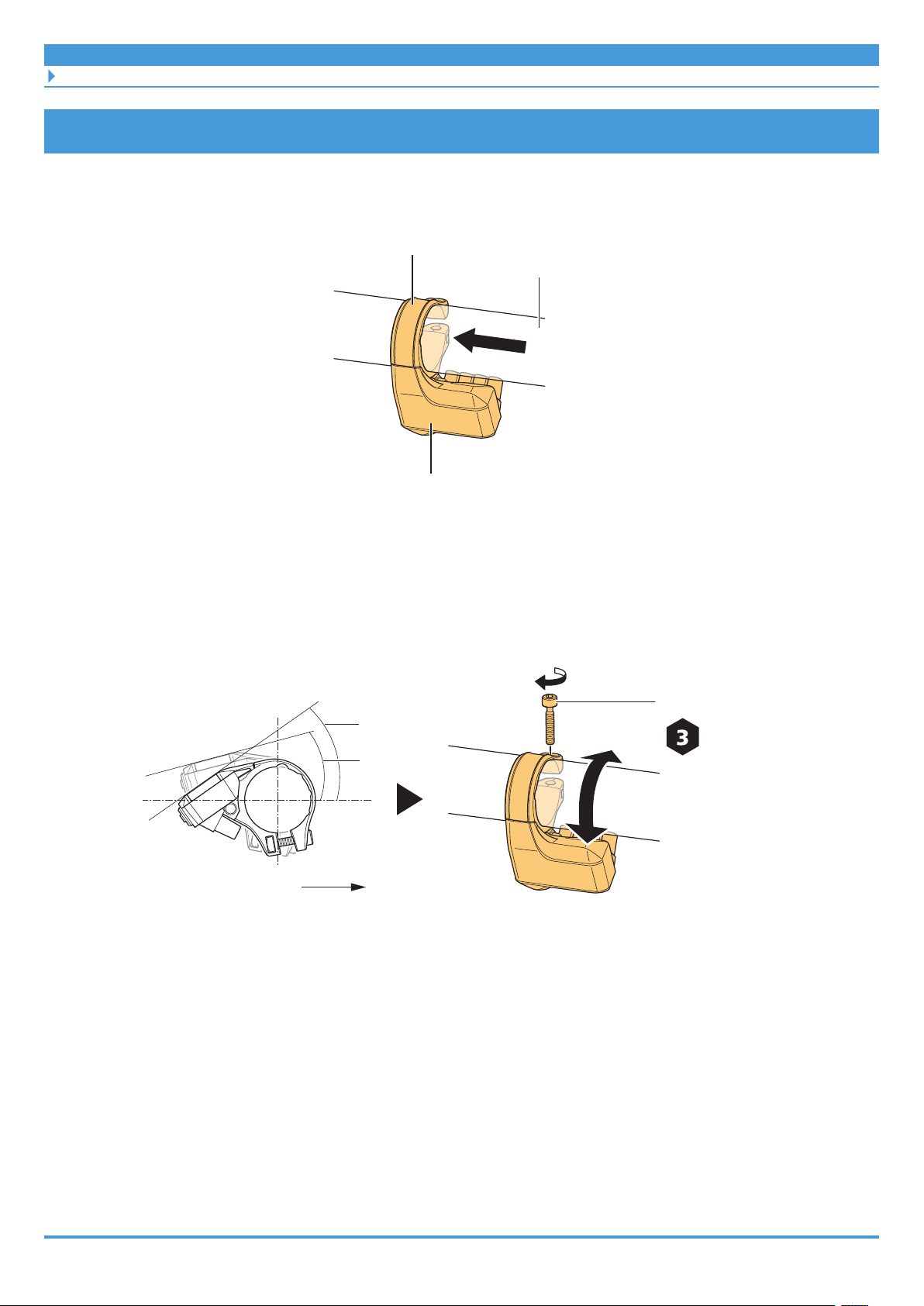
EW-EN100
EW-EN100 is junction [A] with simple operation/display functionality.
Instead of a cycle computer, install it in a location around the cockpit from which the LED can
be seen while riding.
This section explains how to install it to the brake hose. It can be installed to the brake outer
casing using the same procedure.
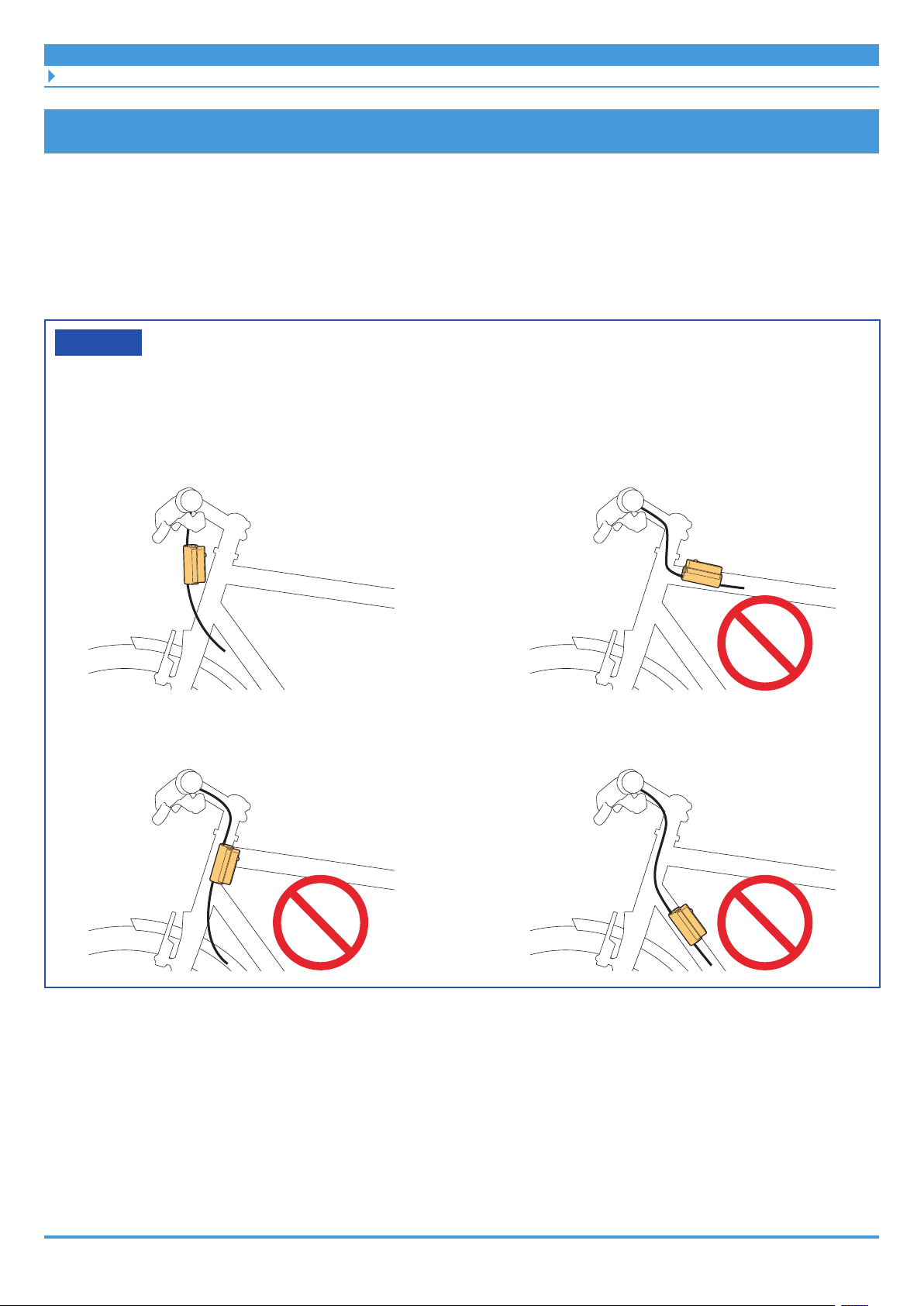
NOTICE
EW-EN100 Installation location
• As shown in the figure, install EW-EN100 so that it does not reach the side of the frame.
Otherwise, it could be damaged if the bicycle tips over and it is pinched between the
frame and curb.
29
Page 30
INSTALLING ELECTRICAL PARTS
Installing the Cycle Computer/Junction [A]
1. Determine the EW-EN100 installation location, and then set the
adapter.
(1) Open up the adapter and set it to the brake hose.
(2) Bend the adapter along the brake hose.
(2)(1)
Adapter
Brake hose or
brake outer casing
EW-EN100
Align the holes with this area
inward
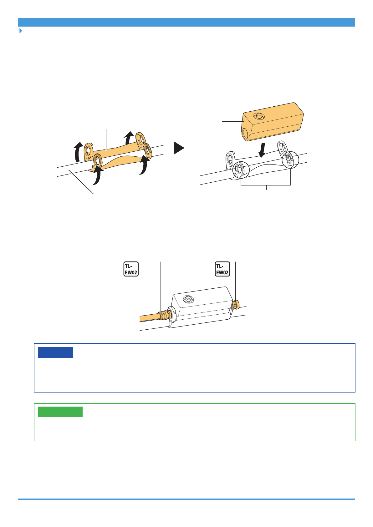
2. As shown in the figure, set EW-EN100 and then connect the electric
wire or dummy plug.
Electric wire Dummy plug
NOTICE
• Be sure to connect either an electric wire or a dummy plug to the two E-TUBE ports on
EW-EN100. Connecting both will secure EW-EN100 to the brake hose or brake outer
casing.
TECH TIPS
• When removing it, reverse the procedure.
30
Page 31

INSTALLING ELECTRICAL PARTS
Installing the Switch Unit
Installing the Switch Unit
Install the assist switch and shift switch (for electronic gear shifting) to the handlebar.
SW-E6010
• Install SW-E6010-L to the left side of the handlebar (the assist side by default) and SW-E6010-R
to the right side (the shift side by default).
• SW-E6010 can be installed to Ø22.2 handlebars.
1. Temporarily attach the cord bands.
Cord bands are included with the switch unit.
• Temporarily attach the cord bands to the switch unit cable.
• Adjust the number of cord bands according to the
length of the handlebar.
Cord band
2. Push the cord bands and switch unit along from the edge of the
handlebar.
For the switch unit, the electric wire must be facing downward.
31
Page 32

INSTALLING ELECTRICAL PARTS
Installing the Switch Unit
3. Open the mounting bolt cover, and then tighten the mounting bolt.
Mounting bolt
TECH TIPS
• When removing it, reverse the procedure.
SW-E7000
Mounting bolt cover
1.5 N·m
• Install SW-E7000-L to the left side of the handlebar (the assist side by default) and SW-E7000-R
to the right side (the shift side by default).
• SW-E7000 can be installed to Ø22.0 to Ø22.4 handlebars.
1. Temporarily attach the cord bands.
Cord bands are included with the switch unit.
• Temporarily attach the cord bands to the switch unit cable.
• Adjust the number of cord bands according to the
length of the handlebar.
Cord band
32
Page 33

INSTALLING ELECTRICAL PARTS
Installing the Switch Unit
2. Push the cord bands and switch unit along from the edge of the
handlebar.
For the switch unit, the electric wire must be facing downward.
3. Tighten the mounting bolt.
TECH TIPS
• When removing it, reverse the procedure.
Mounting bolt
1.5 N·m
33
Page 34

INSTALLING ELECTRICAL PARTS
Wiring around the Cockpit (SC-E6100)
Wiring around the Cockpit (SC-E6100)
There are three E-TUBE ports in the SC-E6100 bracket. One E-TUBE port must be connected to
the drive unit. At least one of the remaining two E-TUBE ports must be connected to the switch
unit. As an example, this section explains how to connect two switch units.
NOTICE
• Be sure to attach dummy plugs to any unused E-TUBE ports.
1. Wire around the cockpit.
• Connect the electric wires between SC-E6100 and the switch units.
• Switch units and drive units can be connected to any of the E-TUBE ports on SC-E6100.
However, it is recommended to connect the left and right ports to each switch unit, and
the center port to the cycle computer (as shown in the figure).
Left switch
Right switch
Cycle computer
To drive unit
2. Prepare to wire to the drive unit.
Pass the following wires through the frame, and leave them hanging from the drive unit
installation section on the frame.
• Electric wire to connect SC-E6100 and the drive unit
• Electric wire to connect the light and drive unit if installing a light that will use the main
battery as the power source
34
Page 35

INSTALLING ELECTRICAL PARTS
Wiring around the Cockpit (SC-E6100)
Example: Routing the electric wire
This section presents an example of routing an electric wire around the cockpit when using an
SW-E6010 switch unit.
TECH TIPS
• Cord bands are included with the SW-E6010.
• Cable bands are included with the SC-E6100.
` When using cord bands
1. Secure the switch unit's electric wire.
Determine the locations of the cord bands, and then secure the electric wire in place
along the handlebar so that there is no slack.
Switch unit
Cord band
35
Page 36

INSTALLING ELECTRICAL PARTS
Wiring around the Cockpit (SC-E6100)
2. Connect the electric wire to the E-TUBE port on the bracket.
Wrap any slack around the portion of the handlebar between the cycle computer and
stem prior to connecting.
Stem
` When using cord bands and cable bands
1. Secure the switch unit's electric wire.
Determine the locations of the cord bands, and then secure the electric wire in place
along the handlebar so that there is no slack.
Switch unit
Cord band
36
Page 37

INSTALLING ELECTRICAL PARTS
Wiring around the Cockpit (SC-E6100)
2. Use the cable bands to bind the brake outer casing and electric wires
together.
Use the cable bands to bind the brake outer casing and following electric wires.
• Switch unit's electric wire
• Electric wire to connect the cycle computer and drive unit
Brake outer casing
Cable band
To drive unit
3. Connect the electric wire to the E-TUBE port on the bracket.
Wrap any slack around the portion of the handlebar between the cycle computer and
stem prior to connecting.
37
Page 38

INSTALLING ELECTRICAL PARTS
Wiring around the Cockpit (SC-E7000)
Wiring around the Cockpit (SC-E7000)
There are four E-TUBE ports in the SC-E7000 bracket. One E-TUBE port must be connected to
the drive unit. At least one of the remaining three E-TUBE ports must be connected to the
switch unit. As an example, this section explains how to connect two switch units.
NOTICE
• Be sure to attach dummy plugs to any unused E-TUBE ports.
1. Wire around the cockpit.
• Connect the electric wires between SC-E7000 and the switch units.
• Switch units and drive units can be connected to any of the E-TUBE ports on SC-E7000.
However, it is recommended to connect as shown in the figure.
Left switch Right switch
Cycle computer
To drive unit
2. Prepare to wire to the drive unit.
Pass the following wires through the frame, and leave them hanging from the drive unit
installation section on the frame.
• Electric wire to connect SC-E7000 and the drive unit
• Electric wire to connect the light and drive unit if installing a light that will use the main
battery as the power source
38
Page 39

INSTALLING ELECTRICAL PARTS
Wiring around the Cockpit (SC-E7000)
Example: Routing the electric wire
This section presents an example of routing an electric wire around the cockpit when using an
SW-E7000 switch unit.
TECH TIPS
• Cord bands are included with the SW-E7000.
• Cable bands are included with the SC-E7000.
` When using cord bands
1. Secure the switch unit’s electric wire.
Determine the locations of the cord bands, and then secure the electric wire in place
along the handlebar so that there is no slack.
Switch unit
Cord band
39
Page 40

INSTALLING ELECTRICAL PARTS
Wiring around the Cockpit (SC-E7000)
2. Connect the electric wire to the E-TUBE port.
Wrap any slack around the portion of the handlebar between the cycle computer and
stem prior to connecting.
Stem
` When using cord bands and cable bands
1. Secure the switch unit’s electric wire.
Determine the locations of the cord bands, and then secure the electric wire in place
along the handlebar so that there is no slack.
Switch unit
Cord band
40
Page 41

INSTALLING ELECTRICAL PARTS
Wiring around the Cockpit (SC-E7000)
2. Use the cable band to bind the brake outer casing and electric wires
together.
Use the cable band to bind the brake outer casing and following electric wires.
• Switch unit’s electric wire
• Electric wire to connect the cycle computer and drive unit
Brake outer casing
Cable band
To drive unit
3. Connect the electric wire to the E-TUBE port.
Wrap any slack around the portion of the handlebar between the cycle computer and
stem prior to connecting.
41
Page 42

INSTALLING ELECTRICAL PARTS
Wiring around the Cockpit (EW-EN100)
Wiring around the Cockpit (EW-EN100)
As an example, this section explains how to connect a switch unit to EW-EN100.
1. Wire around the cockpit.
To connect the switch unit, use the electric wire to connect EW-EN100 and the switch unit.
EW-EN100
To drive unit
2. Prepare to wire to the drive unit.
Pass the following wires through the frame, and leave them hanging from the drive unit
installation section on the frame.
• Electric wire connecting EW-EN100 and the drive unit
• Electric wire to connect the light and drive unit if installing a light that will use the main
battery as the power source
42
Page 43

INSTALLING ELECTRICAL PARTS
Wiring around the Cockpit (EW-EN100)
Example: Routing the electric wire
This section presents an example of routing an electric wire around the cockpit.
1. Secure the switch unit's electric wire.
Determine the locations of the cord bands, and then secure the electric wire in place
along the handlebar so that there is no slack.
Switch unit
Cord band
EW-EN100
To drive unit
43
Page 44

INSTALLING ELECTRICAL PARTS
Wiring around the Cockpit (EW-EN100)
2. Connect the electric wire to the E-TUBE port on EW-EN100.
If necessary, use cable bands to secure the electric wire connecting the switch unit and
EW-EN100 to either the brake hose or brake outer casing.
Brake outer casing
Cable band
44
Page 45

INSTALLING ELECTRICAL PARTS
Installing the Battery Mount
Installing the Battery Mount
BM-E6000
1. Install the mount lower case to the key unit.
Key unit mounting bolt A (one-way type)
1.6 - 1.8 N·m
Key unit mounting bolt B
1.6 - 1.8 N·m
Key unit
Mount lower case
45
Page 46

INSTALLING ELECTRICAL PARTS
Installing the Battery Mount
2. Set the plug unit to the mount lower case, and install it to the battery
rail.
(1) Set the plug unit to the mount lower case.
(2) Set the battery rail to the mount lower case. Be careful not to pinch the power cord
between the mount lower case and battery rail.
(3) Secure the battery rail.
(1)
Plug unit
Power cord
Battery rail mounting bolt(3)
1.6 - 1.8 N·m
Battery rail(2)
46
Page 47

INSTALLING ELECTRICAL PARTS
Installing the Battery Mount
3. Install the mount upper case.
Mount upper case
Mount upper case mounting bolt
1.1 - 1.3 N·m
47
Page 48

INSTALLING ELECTRICAL PARTS
Installing the Battery Mount
4. Install the battery mount to the rear carrier.
(1) Set the battery mount aligned with the mounting hole on the rear carrier.
(2) Secure the battery mount. Use the bicycle manufacturer's standard tightening torque.
(3) After installing the battery mount, perform the following.
– Firmly close the charging port cap.
– Pass the power cord through the frame and leave it hanging over the drive unit
installation area.
Charging port cap
Battery mount mounting bolt (M5)
NOTICE
• Battery mount mounting bolts (M5) are not included with SHIMANO products. Use the
bolts supplied by the bicycle manufacturer. Contact the bicycle manufacturer for the
tightening torque.
48
Page 49

INSTALLING ELECTRICAL PARTS
Installing the Battery Mount
BM-E6010
1. Install the mount lower case.
Secure the mount lower case on the lower side of the down tube.
Mount lower case mounting bolt
3 N·m
Washer
Mount lower case
Washer
Front of bicycle
49
Page 50

INSTALLING ELECTRICAL PARTS
Installing the Battery Mount
2. Temporarily install the key unit, and then adjust the location of the key
unit.
(1) Temporarily install the key unit on the upper side of the down tube.
(2) Adjust the key unit installation location.
Key unit mounting bolt
(2)
Installation position adjustment
Key unit
Surface A
Mount lower case
Surface B
Key unit
(1)
Temporary
Front of bicycle
Clearance between surface A and
surface B: 223 mm
50
Page 51

INSTALLING ELECTRICAL PARTS
Installing the Battery Mount
3. Secure the key unit.
(1) Temporarily install the key unit cover, and then check the following.
– The battery can be smoothly attached and removed
– There is no rattling in the key unit cover or battery that could result in abnormal noise
when riding
(2) Remove the key unit cover, and then secure the key unit.
(1) Key unit cover
Key unit cover
mounting bolt
(Temporary)
Battery
(2)
Key unit mounting bolt
3 N·m
51
Page 52

INSTALLING ELECTRICAL PARTS
Installing the Battery Mount
4. Install the key unit cover and the rattling prevention spacer.
(1) Secure the key unit cover.
(2) Peel the release liner from the back, and then attach the rattling prevention spacer to
the key unit cover.
(1) Key unit cover Rattling prevention spacer
Key unit cover
mounting bolt
Adhesive tape
(2)
0.6 N·m
NOTICE
• Check that there is no oil or other foreign matter on the adhesive surface of the
adhesive tape on the rattling prevention spacer or on the adhesion surface on the key
unit cover. Remove any oil or other foreign matter before attaching.
52
Page 53

INSTALLING ELECTRICAL PARTS
Installing the Battery Mount
5. Install the mount upper case.
(1) Open the charging port cap and pull it out fully.
(2) Insert the plug unit into the mount lower case. Make sure that the plug part of the
plug unit and the charging port are sufficiently exposed from the mount lower case.
(3) Align the two bolt holes on the mount upper case with the mount lower case, and
then tighten the mount upper case mounting bolts.
(4) After installing, perform the following.
– Firmly close the charging port cap.
– Pass the power cord through the frame and leave it hanging over the drive unit
installation area.
Mount upper case mounting bolt
(3)
0.6 N·m
(2)
Plug
Mount lower
case
(1)
Charging port cap
Plug unit
Charging
port
(4)
Charging port cap
Mount upper case
NOTICE
• Check that the power cord is not twisted between the mount upper case and mount
lower case, or otherwise routed in a forced manner.
53
Page 54

INSTALLING ELECTRICAL PARTS
Installing the Battery Mount
BM-E8010
1. Install the mount lower case.
(1) Set the mount lower case on the lower side of the down tube, and then temporarily
install the mounting bolts.
* Temporarily install the two types of bolts as shown in the figure.
(2) Tighten mount lower case mounting bolt A.
(3) Tighten mount lower case mounting bolt B.
Mount lower case mounting bolt A
(Temporary)
(1)
(2)
3 N·m
Metallic spacer
Rubber spacer
Front of bicycle
Mount lower case mounting bolt B
(Temporary)
(1)
(3)
3 N·m
Mount lower case
Frame
Mounting hole
54
Page 55

INSTALLING ELECTRICAL PARTS
Installing the Battery Mount
2. Install the key unit.
Key units are not included with SHIMANO products.
(1) Temporarily install the key unit on the upper side of the down tube.
(2) Adjust the key unit installation location.
(3) Tighten the mounting bolt.
Key unit mounting bolt
(1)
(Temporary)
(3)
3 N·m
(2)
Installation position adjustment
Spacer
Front of bicycle
Spacer
Key unit
Surface A Surface B
Clearance between surface A and
surface B: 224.4 mm
Mount lower case
55
Page 56

INSTALLING ELECTRICAL PARTS
Installing the Battery Mount
3. Install the key unit cover.
(1) Temporarily install the key unit cover.
(2) Try attaching and removing the battery, and check the following.
– The battery can be smoothly attached and removed
– There is no rattling in the key unit cover or battery that could result in abnormal noise
when riding
(3) Secure the key unit cover.
Key unit cover mounting bolt
(Temporary)
(1)
(3)
0.6 N·m
(2)
Key unit cover
Battery
56
Page 57

INSTALLING ELECTRICAL PARTS
Installing the Battery Mount
4. Install the mount upper case.
(1) Pass the power cord from the mount upper case through the hole in the mount lower
case.
(2) Set the mount upper case to the mount lower case.
* Make sure that the rubber bush on the base of the power cord is exposed from
below the mount lower case.
(3) Secure the mount upper case.
(4) Pass the power cord through the frame and leave it hanging over the drive unit
installation area.
Mount upper case mounting bolt
(3)
0.6 N·m
Mount upper case
(2)
Mount lower case
BM-E8020
(1)
Power cord
Rubber bush
If the following cables will be placed inside, pass them through first before installing BM-E8020.
• Electric wire
• Brake hose, brake cable, and shift cable
When installing BM-E8020 inside the frame, be careful that the cables listed above are not
pinched.
57
Page 58

INSTALLING ELECTRICAL PARTS
Installing the Battery Mount
1. Install the mount lower case to the frame.
(1) Set so that any cables built into the down tube pass through the mount installation
area on the frame.
(2) Install the mount lower case on the lower side of the down tube.
Mount lower case mounting bolt(2)
10 N·m
Mount lower case
Frame
Mount installation
area
Built-in cables(1)
(shift wire, electric wire,
and brake wire/brake hose)
Front of bicycle
58
Page 59

INSTALLING ELECTRICAL PARTS
Installing the Battery Mount
2. Install the mount upper case.
(1) Pass the power cord from the mount upper case through the hole in the mount lower
case.
(2) Install the mount upper case to the mount lower case.
Mount upper case mounting bolt
0.6 N·m
Mount upper case
Power cord
Mount lower case
3. Install the cylinder to the key unit.
Key cylinders are not included with SHIMANO products.
Key cylinder
Key unit
Key cylinder mounting bolt
0.6 N·m
59
Page 60

INSTALLING ELECTRICAL PARTS
Installing the Battery Mount
4. Install the key unit.
(1) Make sure that any cables built into the down tube pass through the mount
installation area on the frame.
(2) Temporarily install the key unit on the upper side of the down tube, and then install
the bolt detachment prevention rubber.
(3) Adjust the key unit installation location.
(4) Tighten the key unit mounting bolts.
Key unit mounting bolt
(Temporary)
(2)
(4)
10 N·m
Installation position adjustment
(3)
Key unit
Section A
Battery connection
Section B
unit
Bolt detachment prevention rubber
(2)
Front of bicycle
Built-in cables
(1)
Mount
installation
area
Clearance between section A to section B:
347.2 mm
60
Page 61

INSTALLING ELECTRICAL PARTS
Installing the Battery Mount
5. Install the key unit cover.
(1) Temporarily install the key unit cover.
(2) Try attaching and removing the battery, and check the following.
– The battery can be smoothly attached and removed
– There is no rattling in the key unit cover or battery that could result in abnormal noise
when riding
(3) Secure the key unit cover.
(4) Pass the power cord through the frame and leave it hanging over the drive unit
installation area.
Key unit cover mounting bolt
(Temporary)
(1)
(3)
10 N·m
(2)
Key unit
Battery
Key unit cover
61
Page 62

INSTALLING ELECTRICAL PARTS
Installing the Speed Sensor and Magnet Unit
Installing the Speed Sensor and Magnet Unit
SM-DUE10
If using SM-DUE10 as the speed sensor, set the magnet unit on a spoke on the rear wheel.
The SM-DUE10 installation location is on the inner side of the left side chainstay.
1. Temporarily install the magnet unit to the spoke.
(1) Try pressing the speed sensor to the installation location on the frame, and determine
the installation location of the magnet so that the center of the magnet is aligned
over the tip of the triangle symbol.
(2) Temporarily install the mounting bolt.
Magnet unit
Spoke
Speed sensor
Mounting bolt
(Temporary)
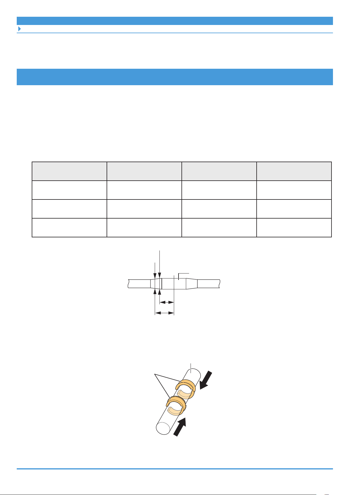
2. Check the clearance between the speed sensor and magnet unit.
Press the speed sensor to the installation location on the frame, and then check the
approximate clearance with the magnet unit. Also take wheel play and frame warping
into consideration.
Clearance between speed sensor and magnet unit
62
Page 63

INSTALLING ELECTRICAL PARTS
Installing the Speed Sensor and Magnet Unit
3. Install the speed sensor.
Clearance between speed sensor
and magnet unit is 3 to 17 mm
Speed sensor mounting bolt (length 16 mm)Toothed washer
Clearance between speed sensor
and magnet unit exceeds 17 mm
Spacer
1.5 - 2 N·m
Speed sensor mounting bolt (length 22 mm)
1.5 - 2 N·m
4. Secure the magnet unit.
(1) Re-check the positioning of the magnet unit and speed sensor.
(2) Secure the magnet unit.
Magnet unit
Spoke
Speed sensor
Mounting bolt
1.5 - 2 N·m
5. Set the electric wire from the speed sensor along the chainstay to the
frame, and wire it to the drive unit.
63
Page 64

INSTALLING ELECTRICAL PARTS
Installing the Speed Sensor and Magnet Unit
SM-DUE11
If using SM-DUE11 as the speed sensor, a special rotor with a built-in magnet must be installed
to the rear wheel. The SM-DUE11 installation location is near the rear wheel axle on the inside
of the left side chainstay.
1. Check that the spokes on the wheel have been laced as shown in the
figure.
The rotor cannot be installed to a wheel with radial lacing.
Front wheel
left side
Rear wheel
left side
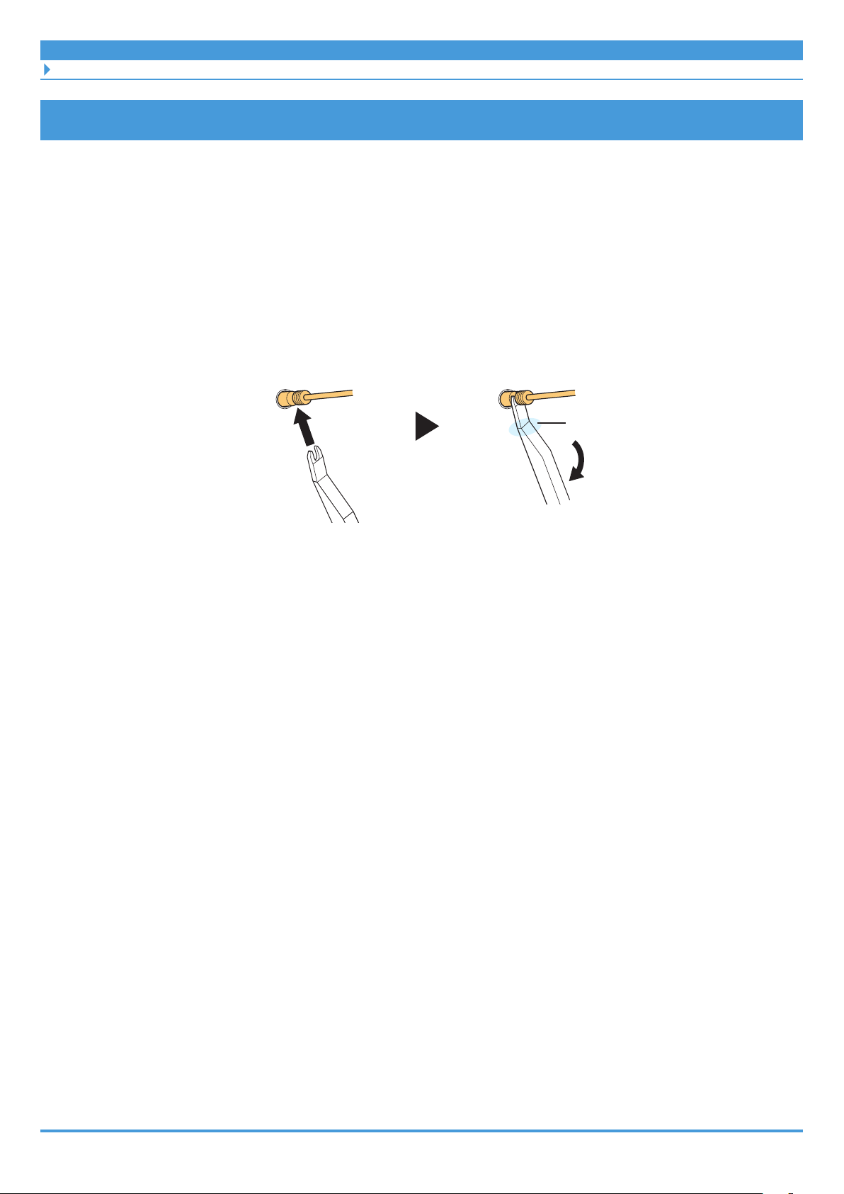
2. Install the rotor.
(1) Set the rotor to the hub on the wheel.
(2) Tighten the rotor fixing lock ring.
Rear wheel
right side
Rotor fixing lock ring
Front wheel
right side
64
40 N·m
Page 65

INSTALLING ELECTRICAL PARTS
Installing the Speed Sensor and Magnet Unit
3. Install the speed sensor to the frame.
Speed sensor mounting bolt
0.6 N·m
4. Set the electric wire from the speed sensor along the chainstay to the
frame, and wire it to the drive unit.
5. Set the rear wheel to the frame.
65
Page 66

INSTALLING THE DRIVE UNIT AND PERIPHERAL PARTS
Installing the Drive Unit
INSTALLING THE DRIVE UNIT AND
PERIPHERAL PARTS
Use the following procedure to install the drive unit and peripheral parts.
(1) Install the drive unit
(2) Wire to the drive unit
(3) Install the drive unit cover
(4) Install the chainrings and crank arms
TECH TIPS
• To check the wiring of the drive unit on a completed bicycle, you will need to first remove
the drive unit cover. Remove the left cover to access the power cord and terminal block.
Installing the Drive Unit
Before installing the drive unit to the frame, first check that all electric wires and cables to
connect to the drive unit have been routed to the installation area of the drive unit.
TECH TIPS
• The drive unit’s (DU-E5000 / DU-E5080) terminal block and power port are located on the
left side of the drive unit.
66
Page 67

INSTALLING THE DRIVE UNIT AND PERIPHERAL PARTS
Installing the Drive Unit
1. Check the three mounting holes on the left and right of the frame, and
then set the drive unit.
Be careful not to pinch electric wires or cables between the frame and drive unit, or to
forcefully bend them.
Mounting hole
Drive unit
67
Page 68

INSTALLING THE DRIVE UNIT AND PERIPHERAL PARTS
Installing the Drive Unit
2. Secure the drive unit to the frame.
(1) Temporarily install the drive unit mounting bolts first on the right side of the frame,
and then on the left side.
(2) Tighten the mounting bolt on the right side so that the drive unit makes firm contact
with the inner surface on the right side of the frame.
(3) Tighten the mounting bolts on the left side of the frame.
Drive unit mounting bolt (M8)
10 - 12.5 N·m
(1) (2)
Right side
Front
(1) (3)
Left side
Rear
TECH TIPS
• Drive unit mounting bolts (M8) are not included with SHIMANO products. Use the
bolts supplied by the bicycle manufacturer.
68
Page 69

INSTALLING THE DRIVE UNIT AND PERIPHERAL PARTS
Connecting the Power Cord
Connecting the Power Cord
Connect the power cord (which has already been routed from the battery mount toward the
drive unit) to the power port on the drive unit. The power port is located on the left side of the
drive unit.
Connection method
1. Connect the power cord.
(1) The arrow marking on the tip of the power cord faces the bottom.
(2) Align the triangle marking on the drive unit's power port with the arrow marking on
the tip of the power cord, and then insert the power cord.
* Check that it is securely connected.
69
Page 70

INSTALLING THE DRIVE UNIT AND PERIPHERAL PARTS
Connecting the Power Cord
Removal method
1. Remove the power cord.
Grab the groove on the plug part of the power cord, and pull it toward you to remove it.
Plug
70
Page 71

INSTALLING THE DRIVE UNIT AND PERIPHERAL PARTS
Connecting Cockpit Peripheral Parts and Electronic Gear Shifting Components
Connecting Cockpit Peripheral Parts and
Electronic Gear Shifting Components
Connect wires from the cockpit peripheral parts (such as the cycle computer and junction [A])
and wires from electronic gear shifting components to the drive unit’s terminal block.
1. Connect the electric wires to the drive unit's terminal block.
• The E-TUBE ports shown in the figure can be used.
• Connect the wire from either the cycle computer or junction [A]. Use junction [B] (SMJC41) to also connect the wire from the electronic gear shifting component (rear or
motor unit).
E-TUBE port
Electric wire
71
Page 72

INSTALLING THE DRIVE UNIT AND PERIPHERAL PARTS
Connecting the Speed Sensor
Connecting the Speed Sensor
Connect the speed sensor's electric wire to the drive unit's terminal block.
1. Connect the electric wire to the drive unit's terminal block.
Use the speed sensor port shown in the figure.
Speed sensor port
Speed sensor's electric wire
72
Page 73

INSTALLING THE DRIVE UNIT AND PERIPHERAL PARTS
Connecting the Light Cables
Connecting the Light Cables
The drive unit contains terminals to supply power for the front and rear lights. Connect the
wires connected to the front and rear lights (that have already been passed through the frame)
to the drive unit.
1. Loosen the mounting bolts on the terminal block.
Mounting bolt
2. Connect the light cables to the light connection terminals, and then
tighten the mounting bolts.
Mounting bolt
Light connection
terminal
0.6 N·m
73
Page 74

INSTALLING THE DRIVE UNIT AND PERIPHERAL PARTS
Installing the Drive Unit Cover
Installing the Drive Unit Cover
This can involve either the single use of a SHIMANO drive unit cover or combined with a drive
unit cover from another company.
SHIMANO drive unit cover only
This section explains how to install SM-DUE50-T or SM-DUE50-C. Although the appearance
varies by model, the example shown here is for SM-DUE50-T.
1. Install the left cover.
(1) Set the left cover to the drive unit from below the bicycle.
(2) Secure the left cover using the three cover mounting bolts.
Cover mounting bolt
0.6 N·m
74
Page 75

INSTALLING THE DRIVE UNIT AND PERIPHERAL PARTS
Installing the Drive Unit Cover
2. Install the right cover.
(1) Set the right cover to the drive unit from below the bicycle.
(2) Secure the right cover using the three cover mounting bolts.
Cover mounting bolt
0.6 N·m
Right cover
75
Page 76

INSTALLING THE DRIVE UNIT AND PERIPHERAL PARTS
Installing the Drive Unit Cover
Used with drive unit cover from other company
This section explains how to install SM-DUE50-TC or SM-DUE50-CC. Although the appearance
varies by model, the example shown here is for SM-DUE50-TC.
Always install the drive unit cover from another company after installing the SHIMANO drive
unit cover.
1. Install the cover on the left side of the drive unit.
Cover mounting bolt
0.6 N·m
Left cover
76
Page 77

INSTALLING THE DRIVE UNIT AND PERIPHERAL PARTS
Installing the Chainring and Crank Arms
Installing the Chainring and Crank Arms
In SHIMANO STEPS, there is an axle for installing the crank arms to the drive unit. Because of
this, the chainring and left/right crank arms should be installed individually to the drive unit.
Set the rear wheel to the bicycle prior to performing the following procedure.
1. Install the left crank arm.
(1) The left crank arm has an "L" marking on one end (the side where the pedal is
installed).
(2) Set with the concave section of the left crank arm aligned with the shape of the axle.
Set so that the round mark on the drive unit axle and installation direction of the
crank arm are in the position shown in the figure.
(3) Tighten the crank arm mounting bolt.
(4) Install the cap.
(1)
Left crank arm
(3)
Crank arm mounting bolt
35 - 50 N·m
(2)
Concave
section
(4)
(4)
Cap
Round
mark
Installation direction
of the crank arm
77
Page 78

INSTALLING THE DRIVE UNIT AND PERIPHERAL PARTS
Installing the Chainring and Crank Arms
2. Set the chainring.
Set with the spline on the chainring aligned with the chainring installation spline on the
drive unit axle.
TECH TIPS
• There are three types of chainrings: those with a chain guard on both the front and
rear sides, those with a chain guard only on the outside, and those with no chain
guard. The explanation in this section uses one without a chain guard.
3. Set the chain.
Chainring installation spline
Axle
Chainring
78
Page 79

INSTALLING THE DRIVE UNIT AND PERIPHERAL PARTS
Installing the Chainring and Crank Arms
4. Secure the chainring.
(1) Prepare the SHIMANO original tool.
(2) Install the lock ring (left screw) by hand.
(3) Use the SHIMANO original tool to tighten the lock ring while firmly pressing the left
crank.
Lock ring
35 - 45 N·m
TECH TIPS
• If using a torque wrench, use TL-FC39 in combination with TL-FC33.
• An impact wrench cannot be used.
79
Page 80

INSTALLING THE DRIVE UNIT AND PERIPHERAL PARTS
Installing the Chainring and Crank Arms
5. Set the right crank arm.
(1) The right crank arm has an "R" marking on one end (the side where the pedal is
installed).
(2) As with the left crank arm, set the right crank arm.
Set so that the round mark on the drive unit axle and installation direction of the
crank arm are in the position shown in the figure.
(3) Tighten the crank arm mounting bolt.
(4) Install the cap.
(2)
Round
mark
(1)
Right crank arm
Installation direction of
the crank arm
Crank arm mounting bolt
(3)
35 - 50 N·m
(4)
Cap
80
Page 81

INSTALLING THE DRIVE UNIT AND PERIPHERAL PARTS
Installing the Arm Covers
Installing the Arm Covers
If the chainring has no chain guard, install the arm covers after installing the chainring to the
drive unit.
1. Set the arm covers to the left and right sides of the chainring.
Install so that the hooks catch the spider arm on the chainring.
Hook
81
Arm cover
Page 82

INSTALLING THE DRIVE UNIT AND PERIPHERAL PARTS
Installing the Arm Covers
2. Tighten the two mounting bolts from the left and right.
For internal geared hub models, proceed to the next section ("Measuring and Adjusting
the Chain Tension").
Mounting bolt
0.8 N·m
Mounting bolt
0.8 N·m
82
Page 83

INSTALLING THE DRIVE UNIT AND PERIPHERAL PARTS
Measuring and Adjusting the Chain Tension
Measuring and Adjusting the Chain Tension
The chain tension must be adjusted for internal geared hub models.
Manual adjustment
1. Check and adjust the chain tension.
Pull the upper side of the chain up and down with a force of around 10 N (1 kgf), roughly
in the middle between the drive unit axle and rear wheel axle. Adjust the chain tension
so that the chain has a slack of 15 mm or more.
83
Page 84

HANDLING THE BATTERY
Installing the Battery
HANDLING THE BATTERY
Installing the Battery
The battery is secured to the battery mount with a key. There are several types of keys, so there
may be differences with the explanation below.
CAUTION
• Firmly hold the battery during installation, being careful not to drop it.
• Keep the following in mind to prevent the battery from dropping while riding.
– Check that the battery is locked firmly with the battery mount.
– Do not ride with the key inserted.
NOTICE
• Check that the charging port cap is closed before riding.
TECH TIPS
• The battery can be inserted without turning the key.
84
Page 85

HANDLING THE BATTERY
Installing the Battery
Rear carrier mount type
1. Insert the battery into the rail from the rear of the bicycle.
Slide the battery to the front and push it in firmly.
2. Remove the key.
Return the key to the locked position, and then remove it.
Rail
85
Page 86

HANDLING THE BATTERY
Installing the Battery
Down tube mount type
1. Insert the battery from below.
Align the concave section on the bottom of the battery with the convex section on the
battery mount, and then insert the battery.
2. Slide the battery.
Push it in firmly until you hear it click into place.
3. Remove the key.
Return the key to the locked position, and then remove it.
86
Page 87

HANDLING THE BATTERY
Removing the Battery
Built-in type
The following procedure uses a type of frame where the battery is installed/removed from its
lower side as an example.
1. Use the following procedure to insert from the lower side of the
battery.
(1) Insert from the lower side of the battery.
(2) Slide the battery. Push it in firmly until you hear it click into place.
(2)
(1)
Removing the Battery
CAUTION
• Firmly hold the battery during removal or transport, being careful not to drop it.
87
Page 88

HANDLING THE BATTERY
Removing the Battery
Rear carrier mount type
1. Insert the key and release the lock.
(1) Turn the power OFF, and then insert the key into the socket on the battery mount.
(2) Turn the key until you feel it make contact.
Key
Socket
Press power switch to turn power OFF
2. Carefully remove the battery.
Down tube mount type
1. Insert the key.
Turn the power OFF, and then insert the key into the socket on the battery mount.
< BT-E6010 >
Press power switch to turn power OFF
Key
< BT-E8010/BT-E8014 >
Socket
Press power switch to turn power OFF
88
Page 89

HANDLING THE BATTERY
Removing the Battery
2. Release the battery lock.
Turn the key until you feel it make contact.
3. Slide and carefully remove the battery.
Built-in type
If a battery cover from another company is installed, remove the battery cover first. The
following procedure uses a type of frame where the battery is installed/removed from the lower
side of the down tube as an example.
1. Open the socket cap.
Press the power switch to turn the power OFF, and then open the socket cap.
Socket cap
Power switch
89
Page 90

HANDLING THE BATTERY
Removing the Battery
2. Release the battery lock.
(1) Insert the key into the socket on the battery mount.
(2) Turn the key.
* The plate spring will hold the battery and prevent it from dropping.
(3) Push the key in to release the lock.
* The battery lock will be released, so be sure to hold it firmly.
Socket
(1)
(2)
Key
(3)
3. Remove the battery.
(1) Remove the key, and then close the socket cap.
(2) Carefully remove the battery.
NOTICE
• Do not install or remove the battery with the key inserted or the socket cap left open.
The battery could make contact with the handle on the key or the socket cap,
damaging it.
90
Page 91

HANDLING THE BATTERY
Charging the Battery
Charging the Battery
Deep sleep mode
The battery will be in deep sleep mode immediately after shipment, so it cannot be used right
away. Charging the battery using the designated battery charger will cancel deep sleep mode,
allowing the battery to be used. The battery can be used when the LED on it turns on.
TECH TIPS
• You can also cancel deep sleep mode by connecting a completed bicycle (i.e. a bicycle to
which all components have been assembled) to E-TUBE PROJECT.
NOTICE
Although the battery can be charged regardless of the battery level, fully charge the battery in
the following situation. Use the designated battery charger to charge the battery.
• The battery is not ready for use at the time of shipment. Before riding, be sure to fully charge
the battery.
If the battery has become completely empty, charge it as soon as possible. Leaving the battery
discharged could cause it to deteriorate.
• If the bicycle will not be ridden for a long time, store with the battery level at around 70%.
Charge the battery every six months to prevent it from fully discharging.
• Do not connect to E-TUBE PROJECT while the battery is being charged.
It is recommended to use a genuine SHIMANO battery. If using a battery from another
company, be sure to read the product manual thoroughly prior to use.
• You can check whether a battery is a SHIMANO genuine battery or a battery from another
company by connecting to E-TUBE PROJECT and running the [Connection check] menu.
DANGER
• Use the specified battery and battery charger combination for charging and observe the
specified charging conditions. Doing otherwise may cause overheating, bursting, or
ignition.
CAUTION
• When charging a battery attached to the bicycle, be careful not to pull the charging cable.
Doing so could cause injury, or could cause the bicycle to tip over, damaging components.
91
Page 92

HANDLING THE BATTERY
Charging the Battery
NOTICE
• When removing the battery charger's power plug from the electrical outlet or removing
the power plug from the battery, do not pull while holding the cord. Doing so may cause
damage.
• If the bicycle is stored for an extended period of time immediately after purchase, you will
need to charge the battery before using the bicycle. Once the battery is charged, the
charging capacity starts to deteriorate slightly.
Charging time
The charging time will vary depending on the maximum capacity of the battery, the battery
level, and the battery charger being used.
` Designated charging time
The charging time from a battery level of 0% is as shown below.
Designated charging time
Battery
Battery charger: EC-E6002 Battery charger: EC-E6000
BT-E6000 / BT-E6010 / BT-E8014 About 6.5 hours About 4 hours
BT-E6001 / BT-E8010 / BT-E8020 About 7.5 hours About 5 hours
WARNING
• If the battery does not become fully charged even two hours after the designated
charging time, immediately unplug the battery from the electrical outlet and contact the
place of purchase. Doing otherwise may cause overheating, bursting, or ignition.
92
Page 93

HANDLING THE BATTERY
Charging the Battery
Charging the battery removed from the bicycle
Charge the battery placed on a level surface indoors.
` BT-E6000/BT-E6001/BT-E6010
An adapter (SM-BTE60: sold separately) is required to charge BT-E6000/BT-E6001/BT-E6010
removed from the bicycle.
1. Open the socket cap.
(1) Install the adapter to the charging plug.
(2) Connect the battery charger’s power plug to the electrical outlet.
(3) Install the adapter to the battery's charging port.
< BT-E6000/BT-E6001 >
Adapter
SM-BTE60
(sold separately)
Charging plug
Adapter
(sold separately)
< BT-E6010 >
SM-BTE60
Charging plug
Charging plug
Adapter
SM-BTE60
(sold separately)
Battery
Charging port
Battery
Charging port
93
Page 94

HANDLING THE BATTERY
Charging the Battery
` BT-E8010/BT-E8014/BT-E8020
1. Connect the battery charger’s power plug to the electrical outlet.
2. Install the charging plug to the battery's charging port.
< BT-E8010/BT-E8014 > < BT-E8020 >
Battery
Charging plug
Charging plug
Battery
Charging port
Charging port
94
Page 95

HANDLING THE BATTERY
Charging the Battery
Charging the battery attached to the bicycle
Charge the battery with the battery charger placed on the floor or some other stable surface.
Fix the bicycle in place when charging, so that it does not tip over.
1. Connect the battery charger’s power plug to the electrical outlet.
2. Insert the charging plug into the charging port on the battery mount
or battery.
< BT-E6000/BT-E6001 > < BT-E8020 >
Battery mount
Battery
Charging port
Charging plug
< BT-E6010/BT-E8010/BT-E8014 >
< BT-E6010 > < BT-E8010/BT-E8014 >
Battery
Charging plug
Charging port
Charging plug
Battery mount
Charging port
Battery
Charging port
Battery
Charging plug
95
Page 96

HANDLING THE BATTERY
Charging the Battery
3. After charging, firmly close the charging port cap.
Charging
port cap
< BM-E6000 > < BM-E6010 >
Charging
port cap
Battery charger LED indication
Once charging has started, the LED on the battery charger lights up.
Lit up Charging
Flashing Charge error
< EC-E6000 > < EC-E6002 >
Battery charger LED
Battery charger LED
Off
Charging
complete
Battery LED indication
The LEDs on the battery can be used to check the charging status of the battery and the battery
level. The shape of the LEDs differ depending on the model number.
Battery LED
96
Page 97

HANDLING THE BATTERY
Charging the Battery
` Display while charging
When charging, the battery LEDs will light up as follows.
LED indication*1 Charging status
0 - 20%
21 - 40%
41 - 60%
61 - 80%
81 - 99%
*1
100%
Off Lit Flashing
97
Page 98

HANDLING THE BATTERY
Charging the Battery
` Battery level display
When the battery power button is used to turn the power from OFF to ON, the LED indication
can be used to check the current battery level.
LED indication*1 Charging status
100 - 81%
80 - 61%
60 - 41%
40 - 21%
20 - 1%
0%
* If the battery is not attached to the bicycle
0%
* If the battery is attached to the bicycle
* If the power is OFF
*1
Off Lit Flashing
TECH TIPS
• When the battery level is low, system functions will be shut off in the following order.
(1) Power assist
* The assist mode will automatically switch to [ECO], and then assist will be shut off. If
using a light connected to the drive unit, the mode will switch more quickly to [ECO].
(2) Electronic gear shifting
(3) Lights
98
Page 99

OPERATION AND SETTING
Turning Power ON/OFF
OPERATION AND SETTING
Turning Power ON/OFF
The main power can be turned ON/OFF using the cycle computer or the battery power button.
NOTICE
• Check the following prior to turning the power ON.
– The battery is firmly attached to the battery mount
– The cycle computer is firmly attached to the bracket
• Do not place your foot on the pedal when operating the power. Doing so could cause a
system error.
TECH TIPS
• When the main power is turned ON, all components connected to the drive unit are also
turned ON (such as assist driving, cycle computer power, the electronic gear shifting
mechanism, and the lights).
• The power cannot be turned ON while charging.
• If the bicycle is left unused for 10 minutes after turning the power ON, the power
automatically turns OFF. (This is the automatic power OFF function.)
Operating power from the cycle computer (SC-E6100)
NOTICE
If the battery level of the cycle computer falls to zero, the cycle computer will not start, and
operations using power will not be possible.
If nothing is displayed on the screen even when the power switch is pressed, perform one of
the following operations to charge the battery.
• Press the power button on the body of the (main) battery to turn the power ON.
• If there is a charging port or if there is a battery mount with a connected charging port
installed, charge the (main) battery from the charging port.
• Use SM-PCE1 or SM-PCE02 to connect to a PC, then charge the built-in battery from the
E-TUBE PROJECT.
The low battery level icon blinks while charging, and disappears once complete.
99
Page 100

OPERATION AND SETTING
Turning Power ON/OFF
1. Press the power switch.
The main power turns ON.
Power switch
Operating power from the battery
1. Press the battery power button.
The LED lights up and the battery level is displayed.
< BT-E6000/BT-E6001 > < BT-E8010/BT-E8014 >
Power switch Power switch
< BT-E6010 > < BT-E8020 >
Power switch
Power switch
TECH TIPS
• Pressing the battery power button on a BT-E8010/BT-E8020 battery for around six
seconds will force the power OFF for emergencies.
100
 Loading...