

Page 1

(English)
DM-HRB001-05
Dealer's Manual
Hub roller brake
BR-C6060-F
BR-C6000
BR-C3000
BR-C3010
BR-IM81
BR-IM86
BR-IM31
BR-IM35
BL-C6000
BL-C6010
BL-IM60-A
Page 2

CONTENTS
IMPORTANT NOTICE .................................................................................... 4
TO ENSURE SAFETY ..................................................................................... 5
INSTALLATION ........................................................................................... 10
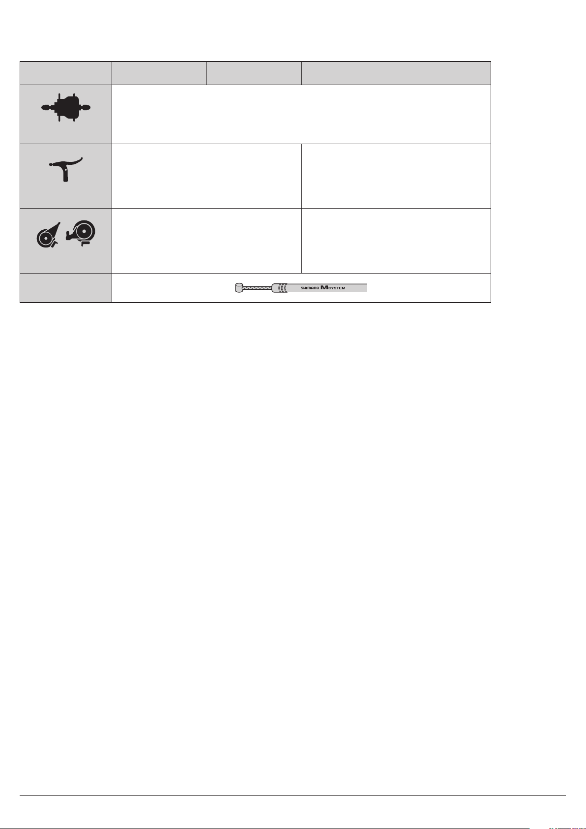
List of tools to be used ............................................................................................................................... 10
Installation of the lever .............................................................................................................................11
Installing the INTER M brake to the hub body ......................................................................................... 11
Installation of the hub to the frame ......................................................................................................... 12
Installation of the brake cable ..................................................................................................................16
ADJUSTMENT ............................................................................................ 23
Adjusting the brake cable .........................................................................................................................23
MAINTENANCE .......................................................................................... 26
Applying grease .........................................................................................................................................26
2
Page 3
List of DM-compatible models
Parts / Series INTER-8 INTER-7 INTER-5 INTER-3
Internal hub gear
Brake lever
Hub roller brake
Brake cable
SG-C6010-8R
SG-C6000-8R
BL-C6010
BL-IM60-A
BR-C3000
BR-C3010
BR-C6000
BR-C6060-F
SG-C3000-7R
SG-5R30
SG-5R35
BL-C6000
BL-IM45
BL-IM65
BL-IM60
BR-IM31
BR-IM35
BR-IM81
BR-IM86
SG-3R40
3
Page 4
IMPORTANT NOTICE
The following instructions must be observed at all times in order to prevent personal injury and physical damage to equipment and surroundings.
The instructions are classified according to the degree of danger or damage which may occur if the product is used incorrectly.
DANGER
Failure to follow the instructions will result in death or serious injury.
WARNING
Failure to follow the instructions could result in death or serious injury.
CAUTION
Failure to follow the instructions could cause personal injury or physical damage to equipment and surroundings.
IMPORTANT NOTICE
•
This dealer’s manual is intended primarily for use by professional bicycle mechanics.
Users who are not professionally trained for bicycle assembly should not attempt to install the components themselves using the dealer’s
manuals.
If any part of the information on the manual is unclear to you, do not proceed with the installation. Instead, contact your place of purchase or a
local bicycle dealer for their assistance.
•
Make sure to read all instruction manuals included with the product.
•
Do not disassemble or modify the product other than as stated in the information contained in this dealer’s manual.
•
All dealer’s manuals and instruction manuals can be viewed on-line on our website (http://si.shimano.com).
•
Please observe the appropriate rules and regulations of the country, state or region in which you conduct your business as a dealer.
For safety, be sure to read this dealer’s manual thoroughly before use, and follow it for correct use.
4
Page 5
TO ENSURE SAFETY
TO ENSURE SAFETY
WARNING
•
When installing components, be sure to follow the instructions that are given in the instruction manuals.
It is recommended that you use only genuine Shimano parts. If parts such as bolts and nuts become loose or damaged, the bicycle may
suddenly fall over, which may cause serious injury.
In addition, if adjustments are not carried out correctly, problems may occur, and the bicycle may suddenly fall over, which may cause serious
injury.
•
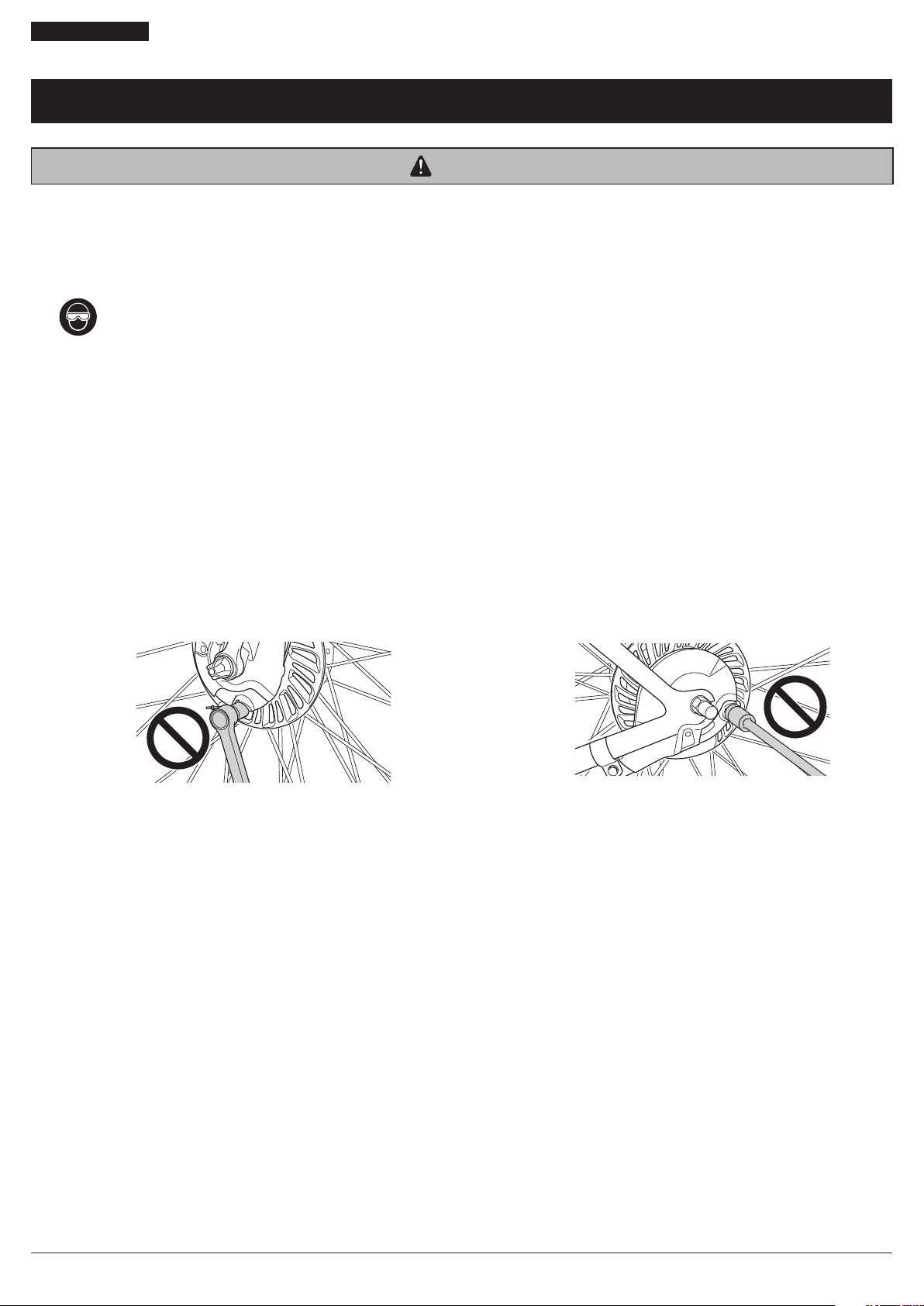
Be sure to wear safety glasses or goggles to protect your eyes while performing maintenance tasks such as replacing parts.
•
After reading the dealer's manual thoroughly, keep it in a safe place for later reference.
Be sure to also inform users of the following:
•
Each bicycle's brake system may handle slightly differently depending on the model. Therefore, be sure to learn the proper braking technique
(including brake lever pressure and bicycle control characteristics) and operation of your bicycle.
Improper use of your bicycle’s brake system may result in loss of control or an accident, which could also lead to severe injury. For proper
operation, consult your professional bicycle dealer or the bicycle's owner's manual. It is also important to practice riding and your braking
technique, etc.
•
You need to use the Shimano front INTER M brake body and the hub as a set (excluding BR-C6060). The hub of the Shimano front INTER M
brake has a built-in power modulator. This system controls the braking force so that excessive force is not applied if the braking force reaches
the specified value. If the front brake is applied too strongly in case the hub is not equipped with the power modulator, the wheel may lock
and the bicycle may fall forward, and serious injury may result.
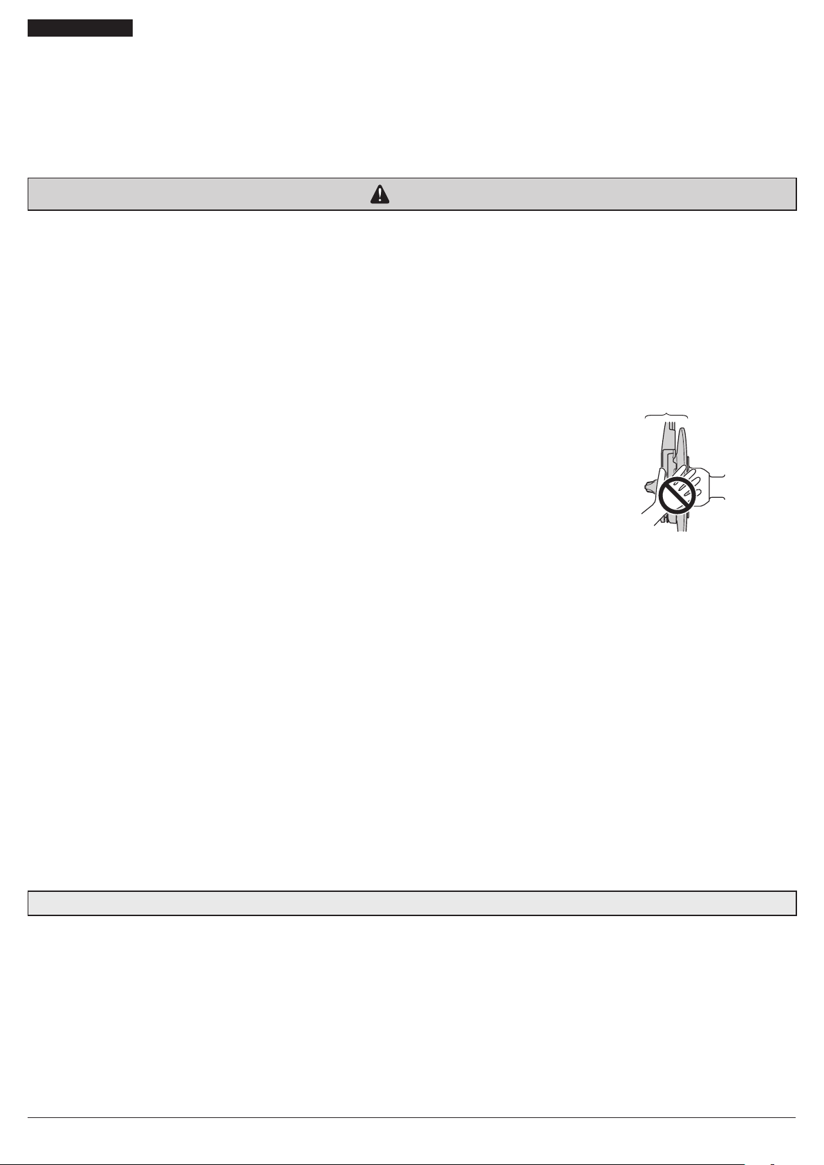
•
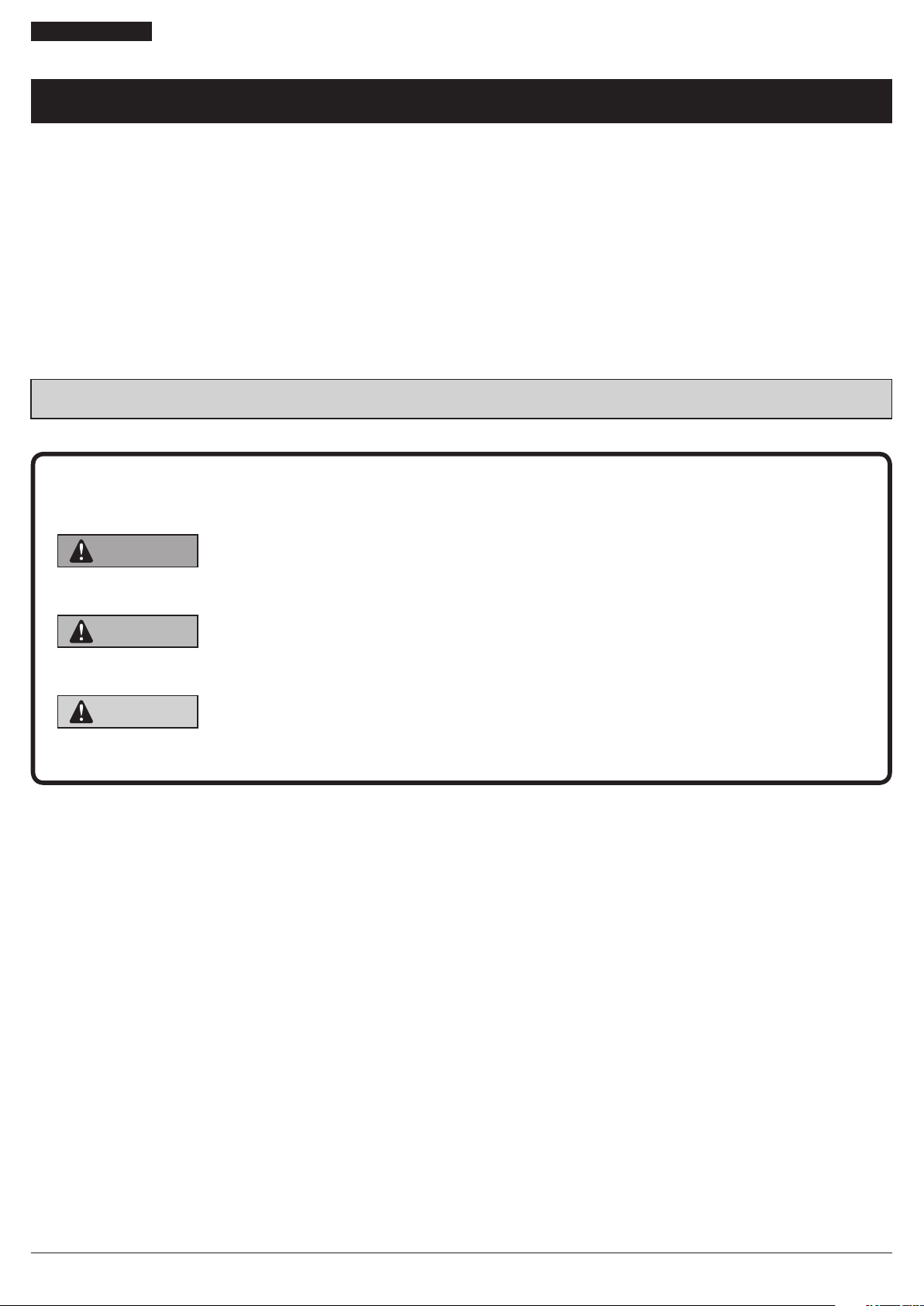
Never tighten the inner cable fixing bolt with it attached to your bicycle. Doing so may cause the inner cable fixing bolt to detach.
< Front >
< Rear >
•
If using the hub roller brakes in combination with a suspension fork, care must be taken when selecting the suspension fork to use. Please
consult with the shop or the bicycle manufacturer. If an incorrect type of suspension fork is selected, it could prevent the suspension fork from
functioning properly because of overheating during braking or lack of strength in the fork, which could result in an accident.
5
Page 6
TO ENSURE SAFETY
•
The brake levers are equipped with a mode switching mechanism to make them compatible with cantilever brakes and roller brakes or
V-BRAKE brakes with power modulator. (BL-C6010 / BL-IM60-A is compatible with roller brakes or V-BRAKE brakes with power modulator.
Please note that it is not compatible with cantilever brakes.)
If the incorrect mode is selected it may cause either excessive or insufficient braking force to occur, which could result in dangerous accidents.
Be sure to select the mode in accordance with the instructions given in the table below.
Mode position Applicable brake
CR position
C : Mode position for compatibility
with cantilever brakes
R : Mode position for compatibility
with roller brakes
For BL-C6010 / BL-IM60-A
R : Mode position for compatibility
with roller brakes
V : Mode position for compatibility with
V-BRAKE brakes with power modulator
V
V
C R
R position
V
R
V position
V
V
C R
C R
C R
•
Cantilever brakes
•
Roller brakes
•
Roller brakes
•
V-BRAKE brakes
with power modulator
Use the brake levers with mode switching mechanism in the combinations given above.
•
When installing components, be sure to follow the instructions that are given in the instruction manuals. It is recommended that you use only
genuine Shimano parts. If parts such as bolts and nuts become loose or damaged, the bicycle may suddenly fall over, which may cause serious
injury.
•
Always make sure that the front and rear brakes are working correctly before you ride the bicycle.
•
If the road surface is wet, the tires will skid more easily. If the tires skid, you may fall off the bicycle. To avoid this, reduce your speed and apply
the brakes early and gently.
•
Check that the wheels are fastened securely before riding the bicycle. If the wheels are loose in any way, they may come off the bicycle and
cause serious injury.
•
After reading the dealer's manual thoroughly, keep it in a safe place for later reference.
For Installation to the Bicycle, and Maintenance:
•
When securing the brake arm to the frame, be sure to use a brake arm clip that matches the size of the chainstay, and securely tighten them
with the clip screw and clip nut to the specified tightening torque.
Use a lock nut with a nylon insert (self-locking nut) for the clip nut. It is recommended that standard Shimano parts be used for the clip screw,
clip nut and brake arm clip.
If the clip nut comes off the brake arm, or if the clip screw or brake arm clip becomes damaged, the brake arm may rotate on the chainstay and
cause the handlebars to jerk suddenly, or the bicycle wheel may lock and the bicycle may fall over, causing serious injury.
•
Depending on the product, the tire diameter of the compatible wheel may differ. Be sure to check the compatible size.
If an incompatible size is used, the wheels may lock and you may lose balance and fall off the bicycle.
6
Page 7
TO ENSURE SAFETY
•
If the total weight of the bicycle (bicycle + rider + luggage) is indicated on the product, the power modulator that controls an excessive
braking effect is built in.
Use the compatible brake lever together. If the total weight of the bicycle is heavier than the recommended range, braking may be
insufficient; if lighter, braking will be too effective and the wheel may be locked, which may cause you to fall off the bicycle.
The power modulator is not an anti-locking device of the wheel.
CAUTION
Be sure to also inform users of the following:
•
If any of the following occur while using the brakes, stop riding immediately and ask the place of purchase to carry out inspection and repairs.
1) If an abnormal noise is heard when the brakes are applied
2) If the braking force is abnormally strong
3) If the braking force is abnormally weak
If 1) and 2) occur, the cause might be a lack of brake grease, so ask the place of purchase to grease the mechanism with special roller brake
grease.
If 2) or 3) occurs when using BR-C6060-F, the power modulator may be malfunctioning. Have it inspected/repaired at the place of purchase.
•
If the brake is used frequently, the area around the brake may become hot. Do not
touch the area around the brake for at least 30 minutes after you finish riding the
bicycle.
Area around the brake
•
Avoid continuous application of the brakes when riding down long slopes, as this will cause the internal brake parts of the Shimano INTER M
brake system to become very hot, and this may weaken braking performance. It may also cause a reduction in the amount of brake grease
inside the brake, and this can lead to problems such as abnormally sudden braking. The design of the Shimano INTER M brake system has been
carried out based on standards such as ISO (4210) and DIN (79100-2). These standards specify the performance for an overall weight of 100 kg.
However, BR-C6000-F/C6060-F is designed with the overall weight assumed to be 130 kg. If the overall weight exceeds 100 kg (130 kg for
BR-C6000-F/C6060-F), the braking force provided by the system may be insufficient for correct braking, and durability of the system may also be
reduced.
•
The front INTER M brake system should only be installed to the left side of a bicycle which is 26 inch” or larger.
If it is used on a bicycle which is smaller than 26 inch”, the braking force may be too great, which could cause accidents.
•
In order to get the best performance from the Shimano front INTER M brake, be sure to use Shimano brake cables and brake levers as a set.
(http://productinfo.shimano.com/lineupchart.html) (The amount of movement of the inner cable must be: 21.5 mm (when using BL-C6010) /
16.5 mm (when using BL-C6000 / BL-IM60 / BL-IM65 / BL-IM45) or more when the brake lever is pressed. If it is less than 21.5 mm / 16.5 mm,
braking performance will suffer, and the brakes may fail to work.)
•
If the brake cable becomes rusted, braking performance will suffer. If this happens, replace the brake cable with a genuine Shimano brake
cable and re-check the braking performance.
•
The brake unit and front hub unit should never be disassembled. If they are disassembled, they will no longer work properly.
•
For BR-C6060-F, the power modulator is built into the brake body so a power modulator is not needed in the hub body. However, the special
front fork is needed to install it.
NOTE
•
Use a wheel with 3x or 4x spoke lacing. Cannot be used with wheels with radial lacing. Otherwise, the spokes or the wheel may be damaged,
or noise may occur when braking.
•
The INTER M brake is different from conventional band brakes in that the inside of the brake drum is filled with grease, causing the turning of
the tire to be slightly heavier than usual. (Particularly in cold weather.)
•
If you apply the front INTER M brake strongly while the bicycle is stopped and then shake the wheel, you will notice that there is a small
amount of gap in the brakes. This is normal, and will not cause any problems at all while riding.
7
Page 8
TO ENSURE SAFETY
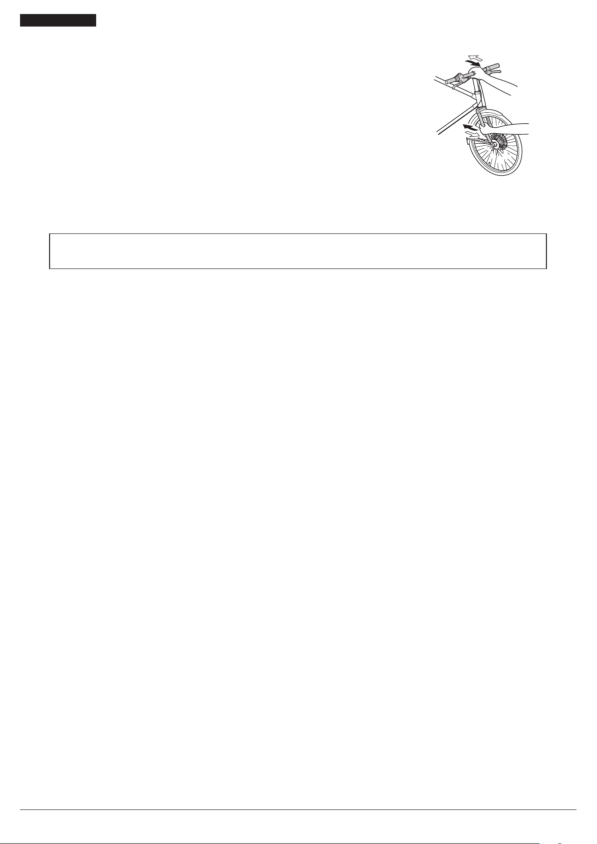
•
To check the amount of looseness in the head parts, grasp the middle of the handlebar
and one of the front forks as shown in the illustration, and then move the head parts
back and forth in the directions indicated by the arrows.
Moreover, because the brakes give a small amount of gap if you apply the brakes fully
and shake the wheel as described above, this will make it more difficult to check the
looseness in the head parts.
•
Products are not guaranteed against natural wear and deterioration from normal use and aging.
•
For maximum performance we highly recommend Shimano lubricants and maintenance products.
The actual product may differ from the illustration because this manual is intended chiefly to explain the procedures for
using the product.
8
Page 9

INSTALLATION
Page 10

INSTALLATION
List of tools to be used
INSTALLATION
List of tools to be used
The following tools are needed for installation, adjustment, and maintenance purposes.
Tool Tool Tool
Adjustable wrench
10 mm spanner 5 mm hexagon wrench
Mode switching
1
2
CR position
V
V
C R
C R
17 mm spanner
Use the screwdriver[#1] to loosen the
screw.
Align the mode position with the CR
position.
Screwdriver[#1]
10
Page 11

INSTALLATION
Installation of the lever
Installation of the lever
(A)
(a)
(B)
Installing the INTER M brake to the hub body
(a)
(a) ɸ22.2 mm
(C)
Engage the serrations on the hub body
(B) with the serrations on the INTER M
brake (A), and then provisionally
tighten the brake unit fixing nut or
the brake unit fixing washer.
(A) Clamp bolt
(B) Grip
(C) 5 mm hexagon wrench
Tightening torque
6 - 8 N·m
(A) INTER M brake
(B) Hub body
(A)
(B)
(a) Align the serrations.
Brake unit
fixing nut
Brake unit
fixing washer
11
Page 12

INSTALLATION
Installation of the hub to the frame
Installation of the hub to the frame
Rear side
The hub installation is an example. Also refer to the manual for the hub.
1
(C)
(E)
(F)
(A)
(B)
(D)
(G)
Mount the chain on the sprocket, and
then set the hub axle (A) into the
dropouts (B).
Place the non-turn washers onto the
right side and left side of the hub axle.
At this time, turn the cassette joint (E)
so that the projecting parts of the nonturn washers fit into the grooves of
the dropouts (D). If this is done, the
cassette joint can be installed so that it
is almost parallel to the chainstay (F).
(A) Hub axle
(B) Dropouts
(C) Non-turn washer (for left side)
(D) Grooves of the dropouts
(E) Cassette joint
(F) Chainstay
(G) Non-turn washer (for right side)
NOTE
When installing a part such as a mudguard
stay to the hub axle, install in the order
shown in the illustration below.
Non-turn
washer
Washer
2
Non-turn washer
Dropouts
Standard
Reversed 6R/Silver 6L/White ϴ = 0°
Reversed
(full chain
case)
Vertical 8R/Blue 8L/Green ϴ = 60° - 90°
Note: vertical: excluding the coaster specifications
Mark/Color
Right Left
5R/Yellow 5L/Brown ϴ ≤ 20°
7R/Black 7L/Gray 20° ≤ ϴ ≤ 38°
5R/Yellow 5L/Brown ϴ = 0°
Size
Mudguard stay
Carrier stay
•
Use whichever non-turn washers match
the shape of the dropouts. Different nonturn washers are used at the left and
right sides.
•
The projecting parts should be on the
dropouts side.
•
Install the non-turn washers so that the
projecting parts is securely in the
dropouts grooves on either side of the
hub axle.
Mark
Cap nut
ϴ
To be continued on next page
12
Page 13

INSTALLATION
Installation of the hub to the frame
Attach the brake arm of the INTER M
(H)
3
(I)
Pull the wheel towards the rear to adjust the chain tension and align the wheel with
4
the frame center.
Temporarily tighten the hub nut strongly.
(J)
(K)
brake to the chainstay with the brake
arm clip (J).
Then temporarily fix the clip screw (K)
and clip nut (I) by lightly tightening
them.
Check that the brake unit is firmly
secured to the hub body with the
brake unit fixing nut or brake unit
fixing washer (H).
5
(H) Brake unit fixing nut/Brake unit
fixing washer
(I) Clip nut
(J) Brake arm clip
(K) Clip screw (M6×16 mm)
NOTE
If the hub nuts are cap nuts, use a frame
with dropouts that are at least 7 mm thick.
Slightly loosen the hub nut.
Fully tighten the brake unit fixing nut.
6
7
(L)
Take up the slack in the chain and
secure the wheel to the frame with the
hub nut (L).
Tightening torque
20 - 25 N·m
(L) Hub nut
Tightening torque
30 - 45 N·m
NOTE
Check that the wheel is fixed securely to
the frame with the hub nuts.
To be continued on next page
13
Page 14

INSTALLATION
Installation of the hub to the frame
8
(O)
(N)
(M)
Fix the brake arm (M) securely to the
chainstay (N) with the brake arm clip
(O).
Check that the brake arm is securely
fastened to the chainstay by the brake
arm clip.
If it is not installed correctly, braking
performance will suffer.
(M) Brake arm
(N) Chainstay
(O) Brake arm clip
Tightening torque
2 - 3 N·m
NOTE
If excessive force is applied to the brake
arm to secure it, the wheel will make noise
and become difficult to turn.
Make sure that you don’t apply excessive
force when installing.
•
When installing the arm clip, securely
tighten the clip bolt while holding the
clip nut with a 10 mm spanner.
•
After installing the brake arm clip, check
that the clip bolt protrudes about 2 - 3 mm
(4 mm for BR-IM31/35) from the surface of
the clip nut.
Clip nut
About 2 - 3 mm
Brake arm
Brake arm clip
Clip screw
(M6 × 16 mm)
14
Page 15

INSTALLATION
Installation of the hub to the frame
Front side
<For quick release type>
1
2
(b)
(C)
(A)
(c)
(D)
(d)
(a)
(B)
Check that the front brake unit (A) is
firmly secured to the hub with the
brake unit fixing nut (B).
(a) With notches (The side with
notches is the front.)
Check that the hub axle (C) is touching
the back of the dropout, and that the
end of the brake arm is protruding 11
mm or more from the brazed-on
bracket (D) of the front fork. Check
also that the wheel is firmly secured to
the frame with the quick release or the
hub nut.
If the wheel is not installed properly, it
may come off the frame, which could
result in a serious accident when
riding.
(b) Touching
(c) 11 mm or more
(d) For quick release type:
Secure the cam lever of the quick
release firmly.
(A) Brake unit
(B) Brake unit fixing nut
Tightening torque
15 - 20 N·m
(C) Hub axle
(D) Brazed-on bracket
Cam lever tightening torque
5 - 7.5 N·m
<For nut type>
(E)
(F)
(e)
Check that the front brake unit (F) is
firmly secured to the hub body with
the hub nut (E).
(e) Without notches
(E) Hub nut
(F) Brake unit
Tightening torque
20 - 25 N·m
15
Page 16

INSTALLATION
Installation of the brake cable
Installation of the brake cable
Rear side
1
2
(A)
(B)
(b)
(D)
(a)
(C)
(E)
After checking that the cable
adjustment barrel (B) and adjustment
nut (A) are fully tightened, insert the
outer holder unit (C) into the inner
cable in the direction shown in the
illustration.
After checking that the marking of the
back side of the inner cable fixing bolt
unit (D) is “R”, pass the inner cable
through the hole of the inner cable
fixing bolt unit.
(a) "R" marking
Place the components as shown in the
following figure and tighten the inner
cable fixing nut (E).
Use (b) 99 mm of TL-IM21 (F) to
tighten the inner mounting nut as
shown in the illustration.
(A) Adjustment nut
(B) Cable adjustment barrel
(C) Outer holder unit
(D) Inner cable fixing bolt unit
(E) Inner cable fixing nut
(F) TL-IM21
Tightening torque
6 - 8 N·m
3
(F)
NOTE
•
After tightening, check that the
orientations of the inner cable fixing nut
and inner cable are correct as shown in
the illustration.
•
Never tighten the inner cable fixing bolt
with it attached to brake. The
orientations of the inner cable fixing nut
and inner cable will become improper as
shown in the illustration, which may
cause the inner cable fixing bolt to
detach from the brake body.
To be continued on next page
16
Page 17

INSTALLATION
Installation of the brake cable
4
5
(J)
(c)
(K)
(G)
Align the red mark on the inner cable
fixing washer (H) so that it faces in the
direction of the groove in the winder
unit (G), and then insert the inner
cable fixing bolt unit (I) and push it
into the groove in the winder unit as
(H)
far as it will go.
(c) Insert the inner cable fixing bolt
(I)
unit and push it into the groove
in the winder unit as far as it will
go.
Route the inner cable (J) along the
groove in the winder unit (K).
Insert the outer holder unit (M) into
the hole of the brake arm (L) from
underneath and slide it to the lower
section of the hole.
(G) Groove in the winder unit
(H) Red mark on inner cable fixing
washer
(I) Inner cable fixing bolt unit
(J) Inner cable
(K) Groove in the winder unit
(L) Brake arm
(M) Outer holder unit
6
7
(M)
(O)
(L)
After checking that the outer holder
(N)
unit (O) is inserted as far as it will go
into the brake arm hole, install the
inner end cap (N).
Then, set the inner end cap so that it
does not touch the fin or the spokes.
Turn the cable adjustment barrel (P) to
tighten the inner cable.
(N) Inner end cap
(O) Outer holder unit
(P) Cable adjustment barrel
8
(P)
To be continued on next page
17
Page 18

INSTALLATION
Installation of the brake cable
9
Front side
1
2
(d)
(A)
(B)
(D)
(d)
(a)
(C)
After pressing the lever, check that the
red marks on the inner cable fixing
washer with the inner cable mounting
bolt unit press-fit into the winder unit
are in the right direction as shown in
the illustration.
(d) Red
After checking that the cable
adjustment barrel (B) and adjustment
nut (A) are fully tightened, insert the
outer holder unit (C) into the inner
cable in the direction shown in the
illustration.
After checking that the marking of the
back side of the inner cable fixing bolt
unit (D) is “F”, pass the inner cable
through the hole of the inner cable
fixing bolt unit.
(a) Markings “F”
When detaching the cable, perform in
reverse order.
(A) Adjustment nut
(B) Cable adjustment barrel
(C) Outer holder unit
(D) Inner cable fixing bolt unit
To be continued on next page
18
Page 19

INSTALLATION
Installation of the brake cable
3
(c)
(b)
(d)
(F)
(F)
(E)
(E)
Place the components as shown in the
following figure and tighten the inner
cable fixing nut (E).
Use (b) 109 mm of TL-IM21 (F) to
tighten the inner mounting nut as
shown in the illustration.
Use (d) 101 mm for BR-IM86.
(E) Inner cable fixing nut
(F) TL-IM21
Tightening torque
6 - 8 N·m
NOTE
•
After tightening, check that the
orientations of the inner cable fixing nut
and inner cable are correct as shown in
the illustration.
•
Never tighten the inner cable fixing bolt
with it attached to brake. The
orientations of the inner cable fixing nut
and inner cable will become improper as
shown in the illustration, which may
cause the inner cable fixing bolt to
detach from the brake body.
4
5
(G)
(J)
(K)
Align the red mark on the inner cable
fixing washer (H) so that it faces in the
direction of the groove in the winder
unit (G), and then insert the inner
cable fixing bolt unit (I) and push it
into the groove in the winder unit as
(H)
far as it will go.
(I)
Route the inner cable (K) along the
groove in the winder unit (J).
(G) Groove in the winder unit
(H) Red mark on inner cable fixing
washer
(I) Inner cable fixing bolt unit
(J) Groove in the winder unit
(K) Inner cable
To be continued on next page
19
Page 20

INSTALLATION
Installation of the brake cable
6
7
8
(O)
(P)
(M)
(L)
(N)
(Q)
Hook the inner cable (M) over the
cable hook (L).
Insert the outer holder unit (O) into
the hole of the brake arm (N) from
underneath and slide it to the lower
section of the hole.
After checking that the outer holder
unit (Q) is inserted as far as it will go
into the guide slot in the brake arm,
install the inner end cap (P).
Then, set the inner end cap so that it
does not touch the fin or the spokes.
(L) Cable hook
(M) Inner cable
(N) Brake arm
(O) Outer holder unit
(P) Inner end cap
(Q) Outer holder unit
9
10
(e)
(e)
(R)
Turn the cable adjustment barrel (R) to
tighten the inner cable.
After pressing the lever, check that the
red marks on the inner cable fixing
washer with the inner cable mounting
bolt unit press-fit into the winder unit
are in the right direction as shown in
the illustration.
(e) Red
(R) Cable adjustment barrel
Installation of the brake cable can be
completed by the above procedure. When
detaching the cable, perform in reverse
order.
20
Page 21

INSTALLATION
Installation of the brake cable
<For BR-IM31/35>
1
2
Place the cable adjustment barrel (A)
(A)
(a)
(B)
GREASE
so that it is (a) 13 to 15 mm from the
end of the outer casing holder (B), and
then pass the inner cable through the
cable adjustment barrel and then
through the hole (C) in the inner
mounting bolt.
(A) Cable adjustment barrel
(B) Outer casing holder
(C) Hole in the inner cable fixing bolt
(C)
(D)
(b)
Check that both ends (b) of the outer
casing are securely inserted into the
cable adjustment barrels (D) of both
the brake lever and brake arm.
(D) Cable adjustment barrel
(D)
GREASE
3
Push the link back until it stops. Then,
while pulling the inner cable to apply
the full amount of tension to the
cable, tighten the inner cable fixing
3
GREASE
2
1
(E)
nut (E).
(E) Inner cable fixing nut
Tightening torque
6 - 8 N·m
NOTE
The inner cable has to be set so that it
passes under the link, as shown in the
illustration (c).
(c)
21
Page 22

ADJUSTMENT
Page 23

ADJUSTMENT
Adjusting the brake cable
ADJUSTMENT
Adjusting the brake cable
Rear side
1
2
(a)
(A)
(A)
After checking that the wheel does not
easily turn while the brake cable is
being pulled, depress the brake lever
about 10 times as far as the grip in
order to run in the brake cable.
Turn the cable adjustment barrel (A) of
the brake unit or brake lever so that
there is a 15 mm gap (a) (11 mm for
BL-C6010) in the brake lever.
(The amount of brake lever gap is the
distance from the position where the
brake lever is not operated to the
position where a force is felt suddenly
when the brake lever is pulled.)
NOTE
If the brake cable is not run in, it will need
to be adjusted again after only a short
period of use.
(A) Cable adjustment barrel
3
(B)
After depressing the brake lever to
check the braking performance, secure
the cable adjustment barrel with the
cable adjustment nut (B).
(B) Cable adjustment nut
Tightening torque
1 - 2 N·m
23
Page 24

ADJUSTMENT
Adjusting the brake cable
Front side
1
2
3
(a)
(A)
(A)
(B)
After checking that the wheel does not
easily turn while the brake cable is
being pulled, depress the brake lever
about 10 times as far as the grip in
order to run in the brake cable.
Turn the cable adjustment barrel (A) of
the brake unit or brake lever so that
there is a 15 mm gap (a) (11 mm for
BL-C6010) in the brake lever.
(The amount of brake lever gap is the
distance from the position where the
brake lever is not operated to the
position where a force is felt suddenly
when the brake lever is pulled.)
After depressing the brake lever to
check the braking performance, secure
the cable adjustment barrel with the
cable adjustment nut (B).
NOTE
If the brake cable is not run in, it will need
to be adjusted again after only a short
period of use.
(A) Cable adjustment barrel
(B) Cable adjustment nut
Tightening torque
1 - 2 N·m
24
Page 25

MAINTENANCE
Page 26

MAINTENANCE
Applying grease
MAINTENANCE
Applying grease
(a)
(B)
(A)
(A)
(C)
(B)
Before applying grease for roller
brakes (B), remove the grease hole cap
(A) and press-fit the tube into the back
of the hole 12 mm or more. Apply an
appropriate amount of grease (approx.
5 g) while turning the wheel slowly.
After application, check that braking is
properly applied and that no abnormal
noise is heard.
(a) For BR-C6060-F/C6000/C3000/
C3010
(b) For BR-IM31/35
(A) Grease hole cap
(B) Grease for roller brakes
(C) Cable unit
(b)
(B)
(A)
(B)
(A)
26
Page 27

Please note: specifications are subject to change for improvement without notice. (English)
©
Nov. 2018 by SHIMANO INC. ITP
 Loading...