

Page 1
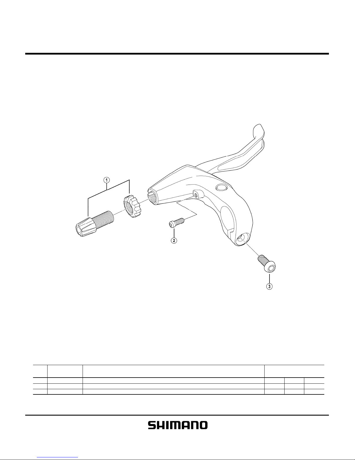
TIAGRA Brake Lever
BL-4600
ITEM
NO.
1
Y8VB98010
Cable Adjusting Bolt & Nut A
2 Y6BX87000 Reach Adjusting Bolt (M4x 10.3) A
3
Y8U806000
Clamp Bolt (M6x 14.8) A
A: Same parts. Mar.-2011-3141
B: Parts are usable, but differ in materirals, appearance, finish, size, etc.
©
Shimano Inc.
A
Absence of mark indicates non-interchangeability.
Specifications are subject to change without notice.
INTERCHANGEABILITY
SHIMANO
CODE NO.
DESCRIPTION
S
L
-
I
M
6
0
S
T
-
T
4
0
0
-
B
L
B
L
-
M
7
7
1
Page 2
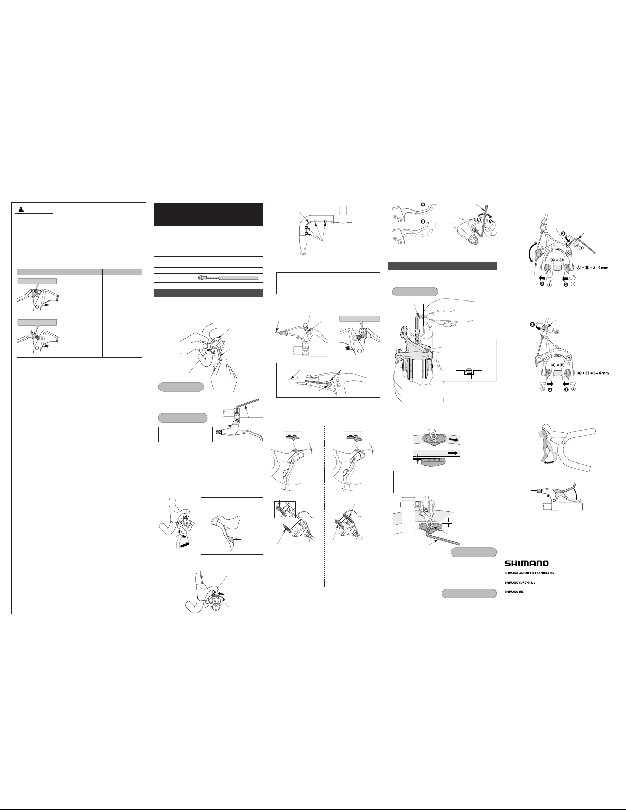
Installation of the brake lever
1. Installation to the handlebar
<ST-4600 / 4603>
Secure the assembly with the installation nut on the outside of
the bracket. Pull the bracket cover back and use a 5 mm Allen
key to ti ghten the bolt.
<BL-4600 / R780>
Use a 4 mm Allen key to install.
<BL-4600 / R780>
5.6 mm
7.5 mm
Initial condition:
4º
4º
8º
14 mm
22 mm
<BL-4600 / R780>
•Mode switching
Bracket cover
5 mm Allen key
Installation nut
General Safety Information
WARNING
•Improper use of your bicycle's brake system may result in a loss of control or
an accident, which could lead to a severe injury.Because each bicycle may
handle differently, be sure to learn the proper braking technique (including
brake lever pressure and bicycle control characteristics) for your bicycle.
Consult your bicycle dealer and the bicycle's owners manual, and practice
your ridi ng and bra king techniq ue.
•The BL-4600/BL-R780 brake levers are equipped with a mode switching
mechanism to make them compatible with V-BRAKE brakes, caliper brakes,
cantilever brakes and roller brakes.
If the incorrect mode is selected it may cause either excessive or
insufficient braking force to occur, which could result in dangerous
accidents. Be sure to select the mode in accordance with the
instructions given in the mode switching table.
•If the front brake is applied too strongly, the wheel may lock and the bicycle
may fall forward, and serious injury may result.
•Use the ST-4600/4603, BL-4600/R780 with the BR-4600.Do not use the BR4600 in combination with previous STI levers for road riding or with the BLR770/BL-R550 brake levers for flat handlebars, otherwise the braking
performance provided will be much too strong.
•Securely tighten the caliper brake mounting nuts to the specified tightening
torque.
·Use lock nuts with nylon inserts (self-locking nuts) for nut-type brakes.
·For sunken nut type brakes, use sunken nuts of the appropriate length
which can be turned six times or more; when re-installing, apply sealant
(locking adhesive) to the nut threads.
If the nuts become loose and the brakes fall off, they may get caught up in
the bicycle and the bicycle may fall over. Particularly if this happens with the
front wheel, the bicycle may be thrown forward and serious injury could
result.
• Brakes designed for use as rear brakes should not be used as front brakes.
• Obtain and read the service instructions carefully prior to installing the
parts. Loose, worn or damaged parts may cause the bicycle to fall over and
serious injury may occur as a result. We strongly recommend only using
genuine Shimano replacement parts.
•Be careful not to allow any oil or grease to get onto the brake shoes.If any
oil or grease do get on the shoes, you should replace the shoes, otherwise
the brakes may not work correctly.
•Check the brake cable for rust and fraying, and replace the cable
immediately if any such problems are found. If this is not done, the brakes
may not work correctly.
•Always make sure that the front and rear brakes are working correctly before
you ride the bicycl e.
•The required braking distance will be longer during wet weather.Reduce
your spee d and apply the brakes early an d gently.
•If the road surface is wet, the tires will skid more easily.If the tires skid, you
may fall off the bicycle. To avoid this, reduce your speed and apply the
brakes early and gently.
•Read the Service Instructions for the Brake Systems carefully before use.
•Read these Technical Service Instructions carefully, and keep them in a safe
place for later reference.
Note
•If using SHIMANO's road brake shoes in combination with ceramic rims, the
brake shoes will wear more quickly than normal.
•If the brake shoes have worn down until the grooves are no longer visible,
they should be replaced.
•Different brake shoes have their own characteristics.Ask the place of
purchase for details when purchasing the brake shoes.
•Parts are not guaranteed against natural wear or deterioration resulting from
normal use.
•For maximum performance we highly recommend Shimano lubricants and
maintenance products.
•For any questions regarding methods of handling or maintenance, please
contact the place of purchase.
– To avoid serious injuries:
When installing the components to carbon frame/handle bar
surfaces, verify with the manufacturer of the carbon frame/parts
for the ir reco mmendati on on t ightenin g torqu e in or der to
prevent over tightening that can cause damage to the carbon
material and/or under tightening that can cause lack of fixing
strength for the components.
Series
TIAGRA
In order to realize the best performance, we recommend
that the following combination be used.
One Holland, Irvine, California 92618, U.S.A. Phone: +1-949-951-5003
Industrieweg 24, 8071 CT Nunspeet, The Netherlands Phone: +31-341-272222
3-77 Oimatsu-cho, Sakai-ku, Sakai-shi, Osaka 590-8577, Japan
* Service Instructions in fur ther languages are available at :
http://techdocs.shimano.com
Please note: specifications are subject to change for improvement without notice. (English)
© Mar.2011 by Shimano Inc. XBC IZM Printed in Malaysia.
Brake lever
ST-4600 / ST-4603, BL-4600 / BL-R780
Caliper Brake
BR-4600
Brake cable
2. Installation of the brake cable
<ST-4600 / 4603>
Tilt the lever in (as when shifting) to make it easier to pass the
cable through the cable hook.
Pass t he in ner c able t hrough as s hown i n the illus tratio n, an d
then set the inner cable drum into the cable hook.
Tightening torque:
6 – 8 N·m {52 – 69 in. lbs.}
Cable hook
Cable hook
Inner cable drum
Inner cable drum
Outer casing
Outer casing
SI-8JY0A-002-00
Outer casing
Tape
Note:
The BR-4600 allows the angle of contact between the shoe
and the rim (toe-in) to be adjusted. Adjusting the toe-in
makes it possible to obtain smoother braking operation.
Note:
Cut the cable at the length at which it is not pulled tight
when the handlebar is turned all the way to the left and
right.
6. Check
Depress the brake lever about 10 times as far as the grip and
check that everything is operating correctly and that the shoe
clearance is correct before using the brakes.
3. Cable connection
Set the quick release lever to the closed position; then adjust
the shoe clearance (as shown in the illustration below) and
secure the cable.
•To increase the lever
stroke
Remove the pad spacer (A)
and install the bump rubber.
•To decrease the lever
stroke
Insert pad spacer (B) as far as
it will go and so that the
projections fit into the holes in
pad spacer (A).
* Apply a small amount of grease to the projections when installing
the pad spacer and the bump rubber.
4. Centering of the brake shoe
Make a minor adjustment by using the centering adjustment
screw.
Depress about
10 times
Depress about
10 times
2. Brake shoe setting position
After adjusting the brake shoe position so that the shoe surface
and the rim surface are as shown in the illustration, tighten the
shoe fixing bolt.
3. Lever stroke adjustment
<ST-4600 / 4603>
Shoe fixing bolt
Centering adjustment
screw
4 mm Allen key
Quick release lever
Installation of the brake
1. Installation of the brake itself
Compress the arch‚ and set while the shoe is in firm contact
with the rim.
5 mm Allen key
Tem p or a r i ly s e cu r e th e o ut e r ca s i ng t o th e h a nd l e ba r ( by u s in g
tape or similar material).
Then wrap the handlebar with handlebar tape.
Open
Closed
5. Readjustment of the shoe clearance
Tur n th e c ab l e a d j u st m e nt b o lt t o r e a dj u s t t h e sh o e cl e a ra n c e.
Cable adjustment bolt
Direction of
rim rotation
Direction of
rim rotation
1 mm or more
Pad spacer (A)
Pad spac er (A )
Pad spac er (A )
Pad spac er (B )
Bump rubber
Pad spacers (A) + (B)
Toe -i n
0.5 mm
Tightening torque:
5 – 7 N·m {43 – 61 in. lbs.}
Tightening torque:
8 – 10 N·m {69 – 87 in. lbs.}
Cable bolt tightening torque:
6 – 8 N·m {52 – 69 in. lbs.}
The usual position during
installation is when the head
of the centering adjustment
screw is as shown in the
illustration.
3 mm Allen key
2 mm Allen key
<ST-4600 / 4603>
<BL-4600 / R780>
Use a handlebar grip with a
maximum outer diameter of
32 mm.
Tightening torque:
6 - 8 N·m {53 - 69 in. lbs.}
4 mm Allen key
Note: The front lever cannot be tilted
to the inside until lever
b
F
is
pushed once or twice.
Lever b
F
Pull
Tilt
Inner cable drum
Cable hook
C/R position
BR-4600
Caliper Brake
Tec h n ic a l Se r v i ce I n st r u ct i o ns SI-8JY0A-002
V
V
C
C
R
R
Mode position Applicable brake
The V indicates the mode
position for compatibility with
V-BRA KE b rak es.
•V-BRAKE brakes
V position
R
V
V
C
C
R
The C indicates the mode
position for compatibility with
caliper brakes and cantilever
brakes.
The R indicates the mode
position for compatibility with
roller brakes.
•Caliper brakes
•Cantilever brakes
•Roller brakes
C/R position
Page 3

V
V
C
C
R
R
R
V
V
C
C
R
V
V
C
C
R
R
R
V
V
C
C
R
Uitsluitend gebruiken in bovenstaande combinaties.
De V geeft de functiestand aan voor
geschiktheid voor gebruik met
zijoptrekremmen en vrijdragende
remmen.
De R geeft de functiestand voor het
gebruik met trommelremmen.
Utiliser seulement les combinaisons ci-dessus.
Le C indique la position de mode pour
la compatibilité avec les freins à étrier
et les freins cantilever.
Le R indique la position de mode pour
la compatibilité avec les freins à
rouleau.
Functiestand
Position de mode
Posição do modo
Rem van toepassing
Frein concerné
Freio aplicável
Utilize somente nas combinações acima indicadas.
O C indica a posição do modo para
compatibilidade com freios de pinça e
freios cantiléver.
O R indica a posição do modo de
operação para compatibilidade com os
freios de rolete.
De V geeft de functiestand aan voor
geschiktheid voor gebruik met VBRAKE remmen.
O V indica a posição do modo para
compatibilidade com os freios VBRAKE.
Le V indique la position de mode pour
la compatibilité avec les freins VBRAKE.
C/ R stand
Position C/ R
Posição C/ R
V stand
Position V
Posição V
Mar. 2011 by Shimano Inc.
TG-8VB0A-001 XBC. IZM. Printed in Malaysia
C
V-BRAKE remmen
Freins V-BRAKE
Vブレーキ
Freios V-BRAKE
Use in the above combinations only.
Cantilever brakes
Roller brakes
Verwenden Sie nur die obenstehenden Kombinationen.
Mit C wird die Position für die
Kompatibilität mit Seitenzug- und
Mittenzugbremsen bezeichnet.
Mit R wird die Betriebsart für die
Kompatibilität mit Klemmrollenbremsen
bezeichnet.
Mittenzugbremsen
Klemmrollenbremsen
Usar sólo en las combinaciones indicadas antes.
La C indica la posición del modo para
compatibilizar con los frenos de
zapatas y frenos cantilever.
La R indica la posición de modo para
compatibilizar con los frenos de rodillo.
Frenos cantilever
Frenos de rodillo
Mode position
Position
Posición de modo
Posizione del modo
Applicable brake
Anwendbare Bremsen
Freno
Freno utilizzabile
Usare solo nelle combinazioni indicate sopra.
La C indica la posizione relativa alla
modalità per la compatibilità con i freni
a pinza e a Cantilever.
La R indica la posizione del modo per
la compatibilità con i freni a rullo.
La V indica la posición del modo para
compatibilizar con los frenos VBRAKE.
La V indica la posizione relativa alla
modalità per la compatibilità con i freni
V-Brake.
Freni a Cantilever
Freni a rullo
C/ R position
C/ R-Position
Posición C/ R
Posizione C/ R
The C indicates the mode position for
compatibility with caliper brakes and
cantilever brakes.
The R indicates the mode position for
compatibility with roller brakes.
The V indicates the mode position for
compatibility with V-BRAKE brakes.
Mit V wird die Position für die
Kompatibilität mit V-BRAKE-Bremsen
bezeichnet.
V position
V-Position
Posición V
Posizione V
WARNUNG
Die Bremshebel sind mit einer
Betriebsartumschaltung ausgerüstet, um sie
kompatibel zu V-BRAKE-Bremsen,
Seitenzugbremsen, Mittenzugbremsen und
Klemmrollenbremsen zu machen. Die Einstellung der
falschen Betriebsart kann zu einem sehr scharfen
oder zu einem zu schwachen Ansprechverhalten der
Bremsen führen, was gefährliche Unfälle
verursachen kann. Wählen Sie deshalb die richtige
Betriebsart, entsprechend den Anweisungen in der
Tabelle Betriebsartumschaltung.
Lesen Sie die Bedienungsanleitung vor der
Verwendung der Bremse sorgfältig.
This brake lever is equipped with a mode switching
mechanism to make it compatible with V-BRAKE
brakes, caliper brakes, cantilever brakes and roller
brakes. If the incorrect mode is selected it may cause
either excessive or insufficient braking force to occur,
which could result in dangerous accidents.
Be sure to select the mode in accordance with the
instructions given in the mode switching table.
Read the Service Instructions for the Brake Systems
carefully before use.
WARNING
V-BRAKE brakes
V-BRAKE-Bremsen
Frenos V-BRAKE
Freni V-BRAKE
Caliper brakes
Seitenzugbremsen
Frenos de zapatas
Freni a pinza
Deze remhendel is uitgerust met een mechanisme
voor functie-overschakeling om deze geschikt te
maken voor gebruik met V-BRAKE remmen,
zijoptrekremmen, vrijdragende remmen en
trommelremmen. Als de verkeerde functie wordt
gekozen, kan dit overmatige of onvoldoende
remkracht veroorzaken dat tot gevaarlijke ongelukken
kan leiden.
Selecteer de functie overeenkomstig de instructies
die gegeven worden in de functieoverschakelingtabel.
Lees voor gebruik zorgvuldig de montage-instructies
voor de remsystemen.
WAARSCHUWING
Esta palanca de frenos está equipada con un mismo
mecanismo de cambio para hacerla compatible con
frenos V-BRAKE, frenos de zapatas, frenos
cantilever y frenos de rodillo. Si se selecciona el
modo incorrecto puede hacer que la fuerza de
frenado sea excesiva o insuficiente, lo que puede
resultar en accidentes peligrosos. Asegúrese de
seleccionar el modo de acuerdo con las instrucciones
indicadas en el cuadro de cambio de modo.
Leer cuidadosamente las instrucciones de servicio
del sistema de freno antes de usarlo.
ADVERTENCIA
Ce levier de frein est équipé d'un dispositif de
commutation de mode qui le rend compatible avec
les freins V-BRAKE, les freins à étrier, les freins
cantilever et les freins à rouleau. Si un mode
incorrect est sélectionné, la force de freinage
obtenue sera excessive ou insuffisante, ce qui risque
de causer des accidents graves.
Veiller donc à sélectionner le mode conformément
aux instructions données dans le tableau de
commutation de mode.
Avant l'utilisation, lire attentivement les instructions
de montage des systèmes de frein.
AVERTISSEMENT
Esta alavanca de freio está equipada com um
mecanismo de mudança de modo para torná-la
compatível com freios V-BRAKE, freios de pinça,
freios cantiléver e freios de rolete. Se for
selecionado o modo incorreto, poderá ocorrer uma
força de frenagem excessiva ou insuficiente, o que
pode resultar em acidentes perigosos.
Certifique-se de selecionar o modo de acordo com
as instruções dadas na tabela de mudança de modo.
Leia as instruções de serviço para o sistema de
freios cuidadosamente antes do uso.
ADVERTÊNCIA
Questa leva del freno è dotata di un meccanismo di
selezione della modalità che la rende compatibile con
i freni V-Brake, a pinza, a Cantilever e a rullo. In caso
di selezione di una modalità non corretta, potrebbe
essere applicata una potenza di frenata eccessiva o
insufficiente ed entrambi i casi potrebbero essere
causa di seri incidenti.
Selezionare la modalità in base alle istruzioni
descritte nella tabella di selezione della modalità.
Prima dell’uso leggere attentamente le Istruzioni
relative all’Assistenza per il Sistema Frenante.
AVVERTENZA
上記の組合わせでご使用ください 。
Cとは、キャリパ ーブレーキ・カン チレバーブ
レーキ対 応のモード位置を意味します。
Rとは、ローラーブレーキ対応 のモード位 置
を意味します。
C・Rの位置
Vrijdragende remmen
Trommelremmen
Freins cantilever
Freins à rouleau
Freios cantiléver
Freios de rolete
Zijoptrekremmen
Freins à étrier
Freios de pinça
カンチレ バーブレーキ
ローラーブレーキ
キャリパーブレーキ
このブレーキレバーには、V-BRAKEまたはキャリパーブレー
キ・カンチレバ ーブレーキ・ローラーブレーキに 対応 するモード
切替えが装着されています。このモード選 択を誤った場合、
極端な効きすぎや制動力不足をひき起こす可能性があり大
変危険です。
モード切 替え表に従いモード選 択を実 施してください。
ブレーキシス テムの 取 扱い 説 明 書もよくお 読みくだ さい 。
警告
モード位置
対応ブレーキ本体
Vとは、Vブレーキ 対応 のモード位置を意味
します 。
Vの位置
 Loading...