

Shimaden SR90 Series Instruction Manual

SR90 Series
Digital Controller
COMMUNICATION INTERFACE
(RS-232C/RS-485)
INSTRUCTION MANUAL
Thank you for purchasing the Shimaden SR90 series controller. Please check that the delivered
product is the correct item you ordered. Please do not begin operating this product until you have
read this instruction manual thoroughly and you understand its contents.
Notice
Please ensure that this instruction manual is given to the final user of the instrument.
Preface
This instruction manual describes the communication interface (RS-232C/RS-485) which is an optional function of the
SR90 series (SR91, SR92, SR93 and SR94). For details of SR90 product’s overview, performance, parameters, how
to install, wiring, operation, and so on, please refer to the separate document "SR90 Series (SR91, SR92, SR93,
SR94) Digital Controller Instruction Manual".
SR90C-1BE
Feb. 2006

Contents
Notice..........................................................................1
Preface........................................................................1
1. Safety rules ............................................................3
2. Outline ....................................................................4
2-1. Communication interface ...........................................4
2-2. Communication protocol and specifications ...............4
3. Connecting controller with host computer.........6
3-1. RS-232C ....................................................................6
3-2. RS-485.......................................................................6
3-3. 3-state output control .................................................6
4. Setting of parameters ...........................................7
4-1. Setting of communication mode.................................7
4-2. Setting of communication protocol .............................7
4-3. Setting of communication address .............................7 6-7. Examples of messages ............................................18
4-4. Setting of communication data format........................7
4-5. Setting of start character............................................8
4-6. Setting of communication BCC ..................................8
4-7. Setting of communication rate....................................8
4-8. Setting of delay time ..................................................8
4-9. Setting of memory mode............................................8
5. Outline of Shimaden protocol..............................9
5-1. Communication procedure.........................................9
(1) Master/slave relation............................................................9
(2) Communication procedure...................................................9
(3) Time-out ............................................................................... 9
5-2. Communication format...............................................9
(1) Outline of communication format .........................................9
(2) Details of basic format section I ......................................... 10
(3) Details of basic format section II ........................................ 10
(4) Outline of text section ........................................................ 11
5-3. Details of Read command (R)..................................13
(1) Format of Read command (R) ...........................................13
(2) Format of normal response to Read command (R) ...........13
(3) Format of error response to Read command (R) ............... 14
5-4. Details of Write command (W) .................................14
(1) Format of Write command (W)........................................... 15
(2) Format of normal response to Write command (W)........... 15
(3) Format of error response to Write command (W) ..............16
5-5. Details of response codes........................................16
(1) Type of response codes..................................................... 16
(2) Order of priority of response codes.................................... 16
6. Outline of MODBUS protocol ............................ 17
6-1. Outline of transfer mode...........................................17
(1) ASCII mode ........................................................................17
(2) RTU mode.......................................................................... 17
6-2. Configuration of messages ......................................17
(1) ASCII mode ........................................................................17
(2) RTU mode.......................................................................... 17
6-3. Slave address ..........................................................17
6-4. Function codes.........................................................17
6-5. Data .........................................................................18
6-6. Error check...............................................................18
(1) ASCII mode ........................................................................18
(2) RTU mode.......................................................................... 18
(1) ASCII mode ........................................................................18
(2) RTU mode.......................................................................... 19
7. Communication data address ........................... 20
7-1. Details of communication data addresses................20
(1) Data address and read/write.............................................. 20
(2) Data address and the number of data ...............................20
(3) Data ...................................................................................20
(4) Read/Write of <Reserved> data ........................................20
(5) Option-related parameters ................................................. 20
(6) Parameters not displayed on the front panel .....................20
7-2. Communication data address ..................................21
8. Supplementary explanation............................... 23
8-1. Table of measuring range codes ..............................23
8-2. Table of event types .................................................24
8-3. ASCII code list..........................................................24
2
1. Safety rules
For matters regarding safety, potential damage to equipment and/or facilities, additional instructions and notes are
indicated by the following headings.
WARNING: This heading indicates hazardous conditions that could cause injury or death of personnel unless
extreme caution is exercised.
CAUTION: This heading indicates hazardous conditions that could cause damage to equipment and/or facilities
unless extreme caution is exercised.
WARNING
The SR90 Series Digital Controller is designed for controlling
temperature, humidity and other physical quantities in general industrial
facilities. It must not be used in any way that may adversely affect the
safety, health or working conditions of those who come into contact with
the effects of its use. When used, adequate and effective safety
countermeasures must be provided at all times by the user. No warranty,
express or implied, is valid when this device is used without the proper
safety countermeasures.
When using this instrument, house it in a control box or the like to
prevent terminals from coming into contact with personnel.
● Do not open this device’s case, or touch the boards or the inside of the
case with your hands or a conductor.
The user should never repair or modify this device.
Doing so might cause an accident that may result in death or serious
bodily injury from electric shock.
CAUTION
To avoid damage to connected peripheral devices, facilities or the product
itself due to malfunction of this device, safety countermeasures such as
proper installation of the fuse or installation of overheating protection
must be taken before use. No warranty, express or implied, is valid if
usage results in an accident when the user has not taken the proper
safety countermeasures
.
Please operate this product safely after referring to and understanding
the safety rules described in the separate Instruction Manual.
3
2. Outline
2-1. Communication interface
There are two types of communication systems, RS-232C and RS-485, employable in the SR90 series communication
interface (however, only RS-485 applies to SR91). Each of them is capable of setting various data for the SR90 and
reading through a personal computer or the like, using signals that comply with EIA standards.
RS-232C and RS-485 are data communication standards established by the Electronic Industries Association of the
U.S. (EIA). The standards cover electrical and mechanical aspects, namely, matters related to applicable hardware
but not the data transmission procedure for the software. Therefore, it is not possible to communicate unconditionally
with an apparatus that has the same interface.
Hence, users need to have sufficient knowledge of product specifications and transmission procedures.
When RS-485 is used, two or more SR90 controllers can be connected to each other. There seems only a few
computers, etc., that support this interface. Use a separately-purchased off-the-shelf line converter for RS-232C <--->
RS-485 to support that interface.
2-2. Communication protocol and specifications
The SR90 Series supports the SHIMADEN standard protocol and MODBUS communication protocol.
Common to each protocol
Signal level EIA RS-232C, RS-485 compliant
Communication system RS-232C 3-line half-duplex system
RS-485 2-line half-duplex multi-drop (bus) system
Synchronization system Start-stop synchronization
Communication distance RS-232C max. 15m
RS-485 max. 500 m (depending on connection conditions)
Communication speed 1200, 2400, 4800, 9600, 19200 bps
Transmission procedure Non-procedural
Communication delay time 1 to 100 x 0.512 msec
Number of connectable devices RS-232C 1
RS-485 max. 31 (depending on connection conditions)
Communication address 1 to 255
Communication memory mode EEP, RAM, R_E
Shimaden protocol
This is a SHIMADEN proprietary communication protocol. The table below lists the specifications of this protocol.
Data format Data length: 7 bits, Parity: Even, Stop bit: 1 bit
Data length Data length: 7 bits, Parity: Even, Stop bit: 2 bits
Parity Data length: 7 bits, Parity: None, Stop bit: 1 bit
Stop bit Data length: 7 bits, Parity: None, Stop bit: 2 bits
Data length: 8 bits, Parity: Even, Stop bit: 1 bit
Data length: 8 bits, Parity: Even, Stop bit: 2 bits
Data length: 8 bits, Parity: None, Stop bit: 1 bit
Data length: 8 bits, Parity: None, Stop bit: 2 bits
Communication code ASCII code
Control code STX_ETX_CR, @_:_CR
Communication BCC ADD, ADD_two’s cmp, XOR, None
4
MODBUS protocol
This is a communication protocol developed for PLCs by Modicon Inc. (AEG Schneider Automation International
S.A.S.)
Though the specifications of this protocol are open, only the communication protocol is defined in this protocol, and
physical layers, such as the communication medium, are not stipulated.
The table below shows the specifications of this protocol.
- ASCII mode
Data format
Data length
Parity
Stop bit
Communication code ASCII code
Control code :_CRLF
Error check LRC
Data length: 7 bits, Parity: Even, Stop bit: 1 bit
Data length: 7 bits, Parity: Even, Stop bit: 2 bits
Data length: 7 bits, Parity: None, Stop bit: 1 bit
Data length: 7 bits, Parity: None, Stop bit: 2 bits
- RTU mode
Data format
Data length
Parity
Stop bit
Communication code Binary data
Control code None
Error check CRC
Data length: 8 bits, Parity: Even, Stop bit: 1 bit
Data length: 8 bits, Parity: Even, Stop bit: 2 bits
Data length: 8 bits, Parity: None, Stop bit: 1 bit
Data length: 8 bits, Parity: None, Stop bit: 2 bits
5
3. Connecting controller with host computer
The SR90 series controller is only provided with 3 lines for input and output, i.e., for data transmission, data reception
and grounding for signals, and not with any other signal lines.
In these instructions, the drawings give an example of control signal processing methods. Please refer to the
documents that came with your host computer for further details.
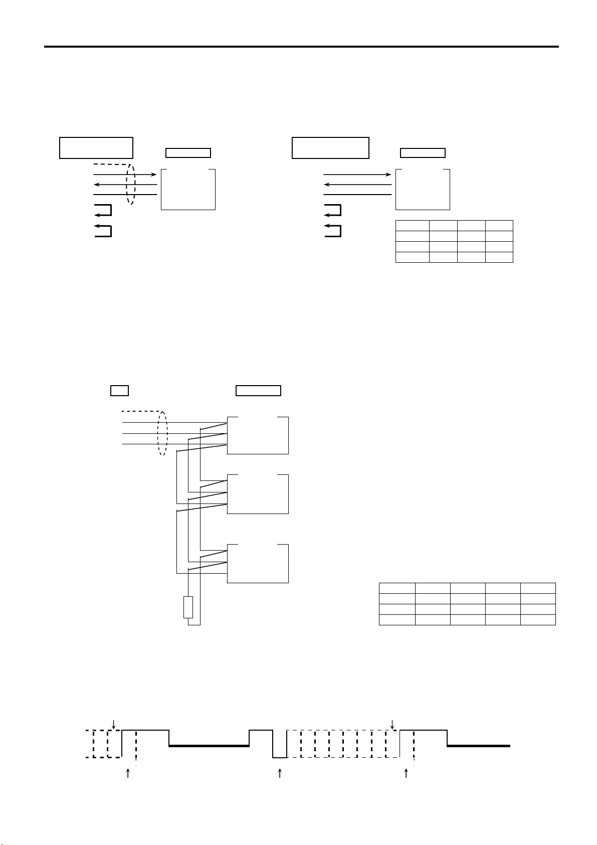
3-1. RS-232C
Host (25 pins) Host (9 pins)
SR90 series [PC/AT
FG ( 1) Controller Controller
SD ( 2) RD Å data reception SD (3) RD Å data reception
RD ( 3) SD Å
SG ( 7) SG Å
data transmission
grounding for signals
RD (2) SD Å
SG (5) SG Å
RS ( 4) RS (7)
CS ( 5) CS (8) SR90 series terminal no.
DR ( 6) DR (6) SR92 SR93 SR94
ER (20) ER (4) SG [ 1] [ 1] [ 1]
SD [ 2] [ 2] [ 2]
*1: Figures in ( ) represent pin numbers of connector. RD [ 3] [ 3] [ 3]
3-2. RS-485
The input/output logical level of the SR90 controller is basically as follows:
In the mark state - terminal < + terminal
In the space state - terminal > + terminal
Until immediately before transmission, however, plus terminals and minus terminals of the controller have high
impedance and outputs at the above levels are produced immediately before starting transmission. (See 3-3. 3-state
output control.)
Host
FG
+
-
SG
Controller 2
SR90 series
Controller 1
+
-
SG
+
-
SG
:
:
Controller N
SR91 SR92 SR93 SR94
SG [ 1] [ 1] [ 1] [ 1]
Terminal resistor + [11] [ 2] [ 2] [ 2]
(120) - [12] [ 3] [ 3] [ 3]
+
-
SG
3-3. 3-state output control
Since RS-485 is of the multi-drop system, transmission output has high impedance always while communication is not carried out or
signals are being received in order to avoid collision between transmission signals. It changes from high impedance to the normal
output condition immediately before transmission and returns to high impedance control simultaneously when transmission
terminates. As the 3-state control is delayed by about 1 msec (maximum) from the completion of transmission of an end character
end bit, however, a few milliseconds' delay should be provided if the host side starts transmission immediately upon reception.
END CHARACTER END CHARACTER
1 Transmitted signal
High impedance High impedance
0
end bit start bit end bit
compatible
] SR90 series
data transmission
grounding for signals
In the case of RS-485, provide it with the attached
Note1:
terminal resistor of 1/2W, 120 across terminals +
and if necessary.
Nevertheless, it should be provided to only the last
controller.
If two or more controllers are provided with terminal
resistors, correct operation cannot be guaranteed.
SR90 series terminal no.
6

4. Setting of parameters
There are the following 9 communication-related parameters for the SR90 series controller. These parameters are
unable to be set or changed by communication; use front key for setting and changing.
When parameters are set, see "6. Explanation of Screen Group and Setting" of the separate instruction manual for the
controller and follow the described steps.
4-1. Setting of communication mode
1-36
Initial value: Loc
Setting range: Loc, Com
4-2. Setting of communication protocol
1-37
4-3. Setting of communication address
1-38
Note 1: Although 1 to 255 addresses are available for setting, the number of connectable controllers is
4-4. Setting of communication data format
1-39
Select communication mode. Front key operation allows only change from Com to Loc, though.
Code Effective command COM lamp
Loc Read
Com Read, write
Unlighted
Lighted
Initial value: shim
Setting range: shim, asc, rtu
Select communication protocol.
Code Protocol
shim Shimaden protocol
asc
rtu
MODBUS ASCII mode
MODBUS RTU mode
Initial value: 1
Setting range: 1 to 255
Select communication protocol.
While one host and one SR90 controller can be connected in the case of RS-232C, one host and 31 SR90
controllers (max.) can be connected in case of RS-485 by the multi-drop system.
Therefore, each instrument is assigned an address (machine No.) so that only the instrument with the
designated address can answer.
31 maximum.
Initial value: 7E1
Setting range: 8 types shown in the following table.
Select either one of the communication data formats shown below
Data length Parity Stop bit Shimaden ASCII RTU
Code
7 bits Even 1 bit
7 bits Even 2 bits
7 bits None 1 bit7 bits
7 bits None 2 bits
8 bits Even 1 bit
8 bits Even 2 bits
None 1 bit8 bits
8 bits None 2 bits
Support
Not Support
7
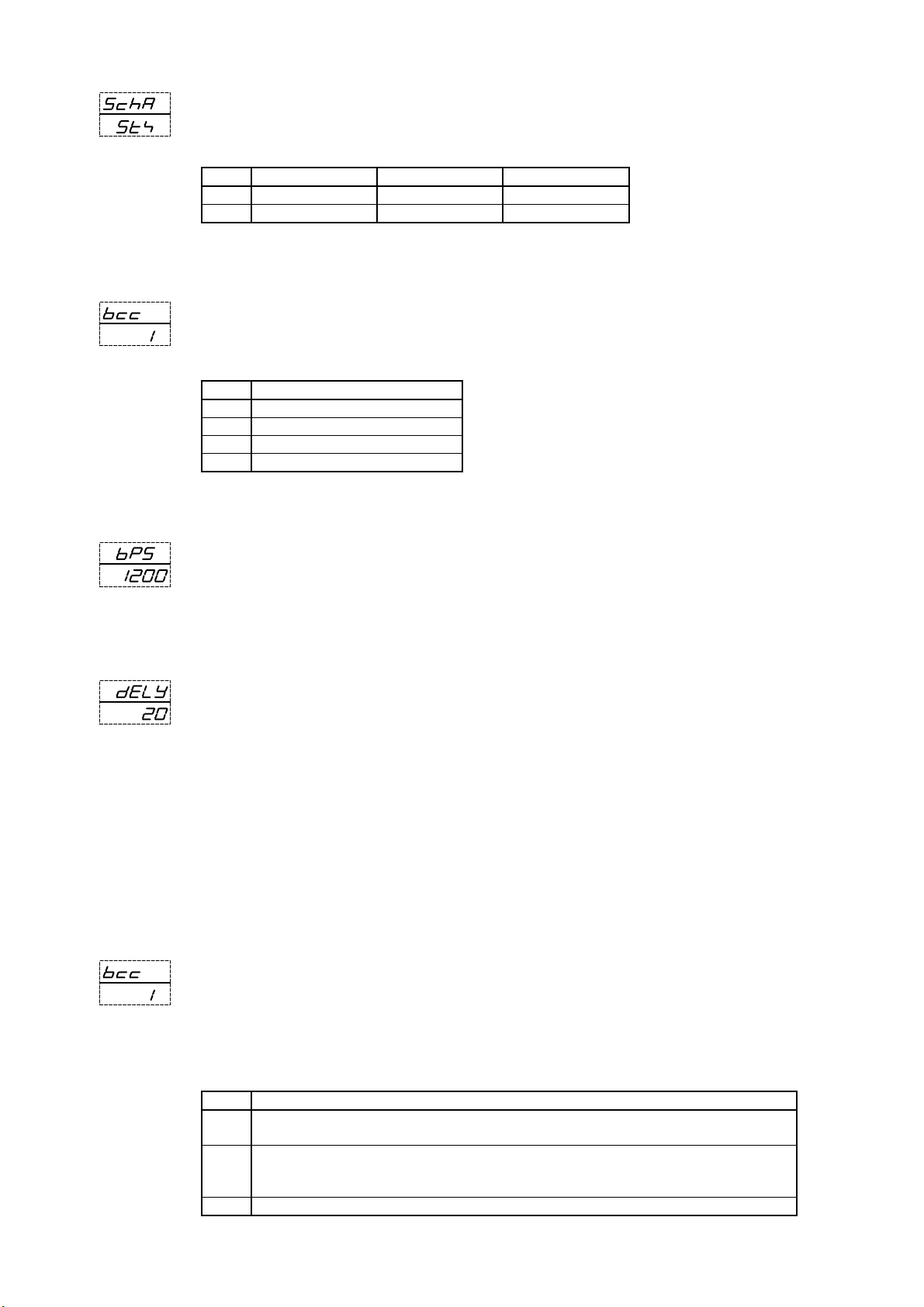
4-5. Setting of start character
1-40
Initial value: STX
Setting range: STX, ATT
Select a control code to be used. This is used for Shimaden protocol only.
Code Start character Text end character End character
STX STX (02H) ETX (03H) CR (0DH)
ATT "@" (40H) ":" (3AH) CR (0DH)
4-6. Setting of communication BCC
1-41
Initial value: 1
Setting range: 1, 2, 3, 4
Select a BCC operation method to be used in BCC checking. This is used for Shimaden protocol only.
Code BCC operation method
1
Addition
2 Addition + 2's complement
3
XOR
4 None
4-7. Setting of communication rate
1-42
Initial value: 1200 bps
Setting range: 1200, 2400, 4800, 9600, 19200 bps
Select a rate at which data are transmitted to host computer.
4-8. Setting of delay time
1-43
Initial value: 20
Setting range: 1 to 100
Set the length of delay time from receipt of a communication command to transmission.
Delay time (msec) = Set value (count) × 0.512 (msec)
Note 1: When RS-485 is used, some converters take longer time for 3-state control than others and it
may lead to signal collision. This can be avoided by increasing delay time. Care should be taken
particularly when the communication rate is slow (1200bps or 2400bps).
Note 2: Actual delay time from receipt of a communication command to transmission is a total of the
above-mentioned delay time and command processing time by software. Particularly for writing
commands, about 400 msecs maybe taken for processing.
4-9. Setting of memory mode
1-44
Initial value: EEP
Setting range: EEP, Ram, r_E
Since the volatile memory EEPROM used in SR90 series has its limits in number of writing cycles, the life of
EEPROM is shortened if SV data or the like are rewritten frequently by communication. To prevent this, in case
data are to be rewritten frequently by communication, set the RAM mode in which only RAM data are rewritten
without rewriting EEPROM, thereby maintaining the life of EEPROM as long as possible.
Code Description
EEP In this mode EEPROM data are also rewritten every time data are changed by communication.
Accordingly, data are maintained when power is turned off.
Ram In this mode only RAM data are rewritten but EEPROM data are not when data are changed by
communication. Therefore, RAM data are deleted when power is turned off. Upon applying power
again, operation starts with data stored in EEPROM.
r_E SV and OUT data are written in RAM. All other data are written in EEPROM.
8
 Loading...